Lowrider 2 - Let the projects begin

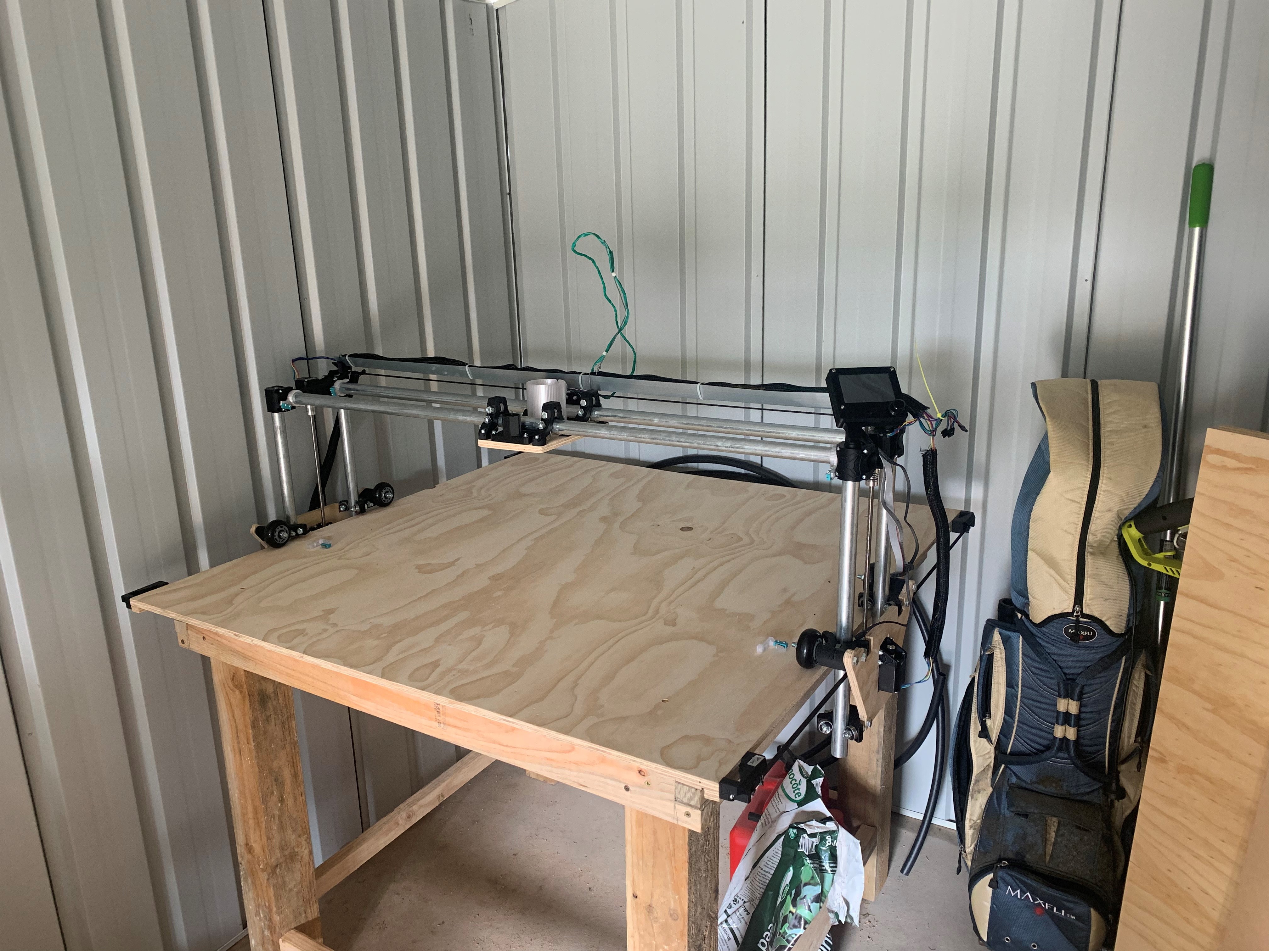
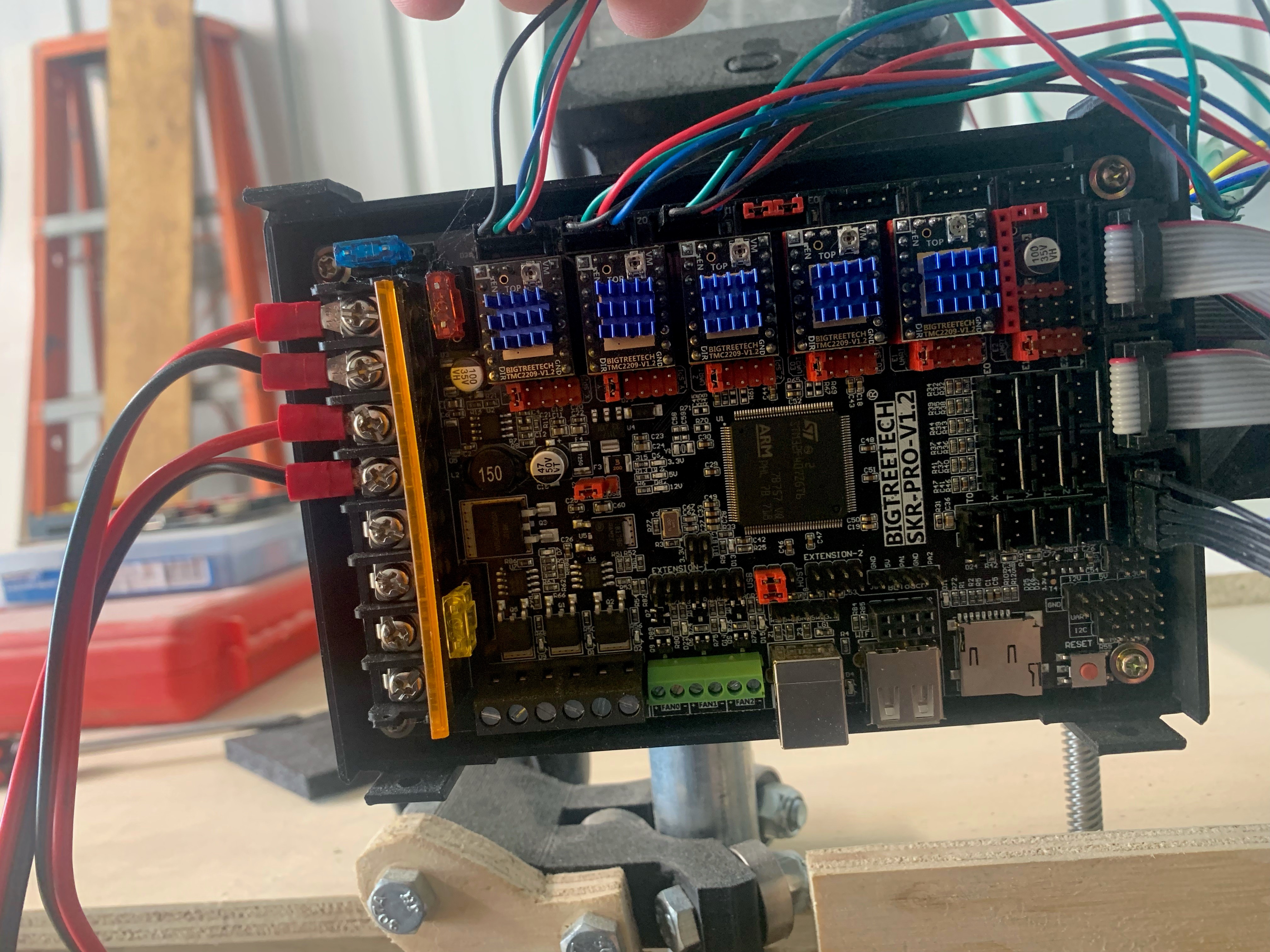
Spoken to likeminded mates, watched a few how to videos and I have finally taken the plunge. Below is my setup (For now :slight_smile: )

There were a few hiccups along the way. I am onto my third skr pro v1.2 board. 1st one (from V1 engineering) was me not watching what I was doing and never realised my child put a pot lid under my board. So school fees paid on that board.

2nd board finally arrived (aliexpress) and it was faulty! couldnt read the sd cards or communicate over usb. So that one was replaced.

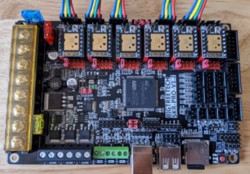
3rd one (ebay) looked like all was ok. UNTIL I noticed a stepper driver not working. Replaced the lot just in case. So the below is what my board looks like now.

I am able to move X and Y but not Z. I tested Z motors in Y slot to make sure its not cabling or motors. All ok there.

I ran m119 through pronterface. and got the following results:

m119
SENDING:M119
Reporting endstop status
x_min: open
y_min: open
y2_min: open
z_max: TRIGGERED
z2_max: open
z_probe: TRIGGERED

So my mistake from my first board has now led me into issues which I dont know how to fix.

firmware I am using is V1CNC_SkrPro_DualLR_2209-2.0.7.2-src

Anyone able to help with a bit of advice to resolve or check?

I don’t know if this is the root of your issues, but you are running dual-endstop firmware which usually has each stepper to be wired individually, but according to your picture, you are only using three of the stepper drivers on the SKR Pro board. I think in theory you should be able to use Dual firmware for a serial/series setup, but you cannot use dual endstops without all five steppers having their own driver. As for the endstops, the only come into play when homing. According to the firmware, z_max is expecting a normally closed connection, and I think that z_probe is expecting a normally open connection.

2 Likes

What does M119 tell you? It is the status of the drivers.

Two comments up.

Oops, I meant M122. Sorry.

Thanks guys, After reading your comments I understand that I have clearly not planned this as well as I should’ve. I am using the series cabling. I Will be making a plan for cabling to suit a dual endstops environment. In the meantime I will flash the firmware to use the series cabling to at least get me going.
This is my project for tonight :slight_smile: will update as I go ok.

1 Like

Based on what I read on the forums from folks who actually have a lowrider (I have a Burly MPCNC), dual endstops and auto-squaring are really not critical to success with using the lowrider. It is very simple to add some stop blocks that you pull the gantry against as you power on the system, and as long as the steppers stay enabled the machine will maintain that level of squareness.

I suggest getting it dirty, add the stop blocks if squareness is a problem, and get a few projects under your belt. Then you’ll be able to decide, based on personal experience with your specific machine, whether the dual endstop configuration is worth the extra work.

1 Like

Ok so I managed to keep the V1CNC_SkrPro_DualLR_2209-2.0.7.2-src. I kept the cabling in series. Except the z axis runs off Z2.

Was just so happy to have z axis moving that I kept it that way for some fun over the weekend.

The crown test worked well

but paid school fees with the next test. I created Gcode for our family crest and ran it. The z axis went as low as it could causing a hole through the material and into the table (smoke everywhere) :slight_smile: thought it was the code and after hours and hours of head scratching found it was actually when I turned the board on it assumed it was at 200mm high on z axis. Tested after manually adjusting Z and turning off and on again at correct height.

I did dance a jig!

1 Like

So I have got the wiring sorted now which looks like below.

image

All working well. I would now like to setup the limit switches.

I have these
image

Can someone please help with a diagram or instructions on how to set it up? Do I need to use all the pins?

Thanks for any suggestions guys.

The pins on the switches will be labelled (C) (NO) and (NC)

(C) is Common, it’s the pin that the switch will connect or disconnect from the other two. Connect this to the (S) – signal – pin on the SKR Pro.

(NO) is Normally Open. that’s the pin that does not connect to C when the switch is untouched, and connects when the switch is closed. This is usually the middle pin. Leave this disconnected.

(NC) is Normally Closed. This pin is normally connected to the (C) pin when the switch is untouched, and disconnects when the switch is pressed. Connect this to the (-) – Negative or Ground – pin on the motherboard.

It doesn’t actually matter if you connect hte (-) and (S) pins backwards, what matters is that the two are shorted together until the switch is triggered.

The board has “pullup resistors” which will bring the voltage on the signal pin up to +5V on the signal pin when it’s left floating. The software reads that as logic HIGH, and will consider that triggered. When you connect the switch, the signal pin gets shorted to ground, and the board will read it as logic LOW, which it will treat as untriggered. As a result, if somehow the switch becomes disconnected, the firmware will read the switch as triggered, which is usually a somewhat safer state, since it will stop moving if the machine is told to home itself. It won’t grind the motors against a hard stop.

Use the command

M119

to test the endstops and check that they are responding as you expect when you trigger them. Make sure that you have the endstops positioned so that the Z1 triggers when the Z1 motor reaches the top of travel. (Yes, the TOP, the highest point, not the bottom) and the Z2 stop for the Z2 motor. Similarly, the Y1 stop needs to pair with the Y1 motor, and Y2 stop with Y2 motor. Crossing these to the wrong side will result in incorrect behaviour. X just needs to trigger for X minimum.

A touch probe is used for Z MIN, The V1 touch plate (Or other touch plate) will work just fine. Ground the tip of the tool, and connect the signal pin to the touchplate.

1 Like

Thanks for that Dan I will give it a go.