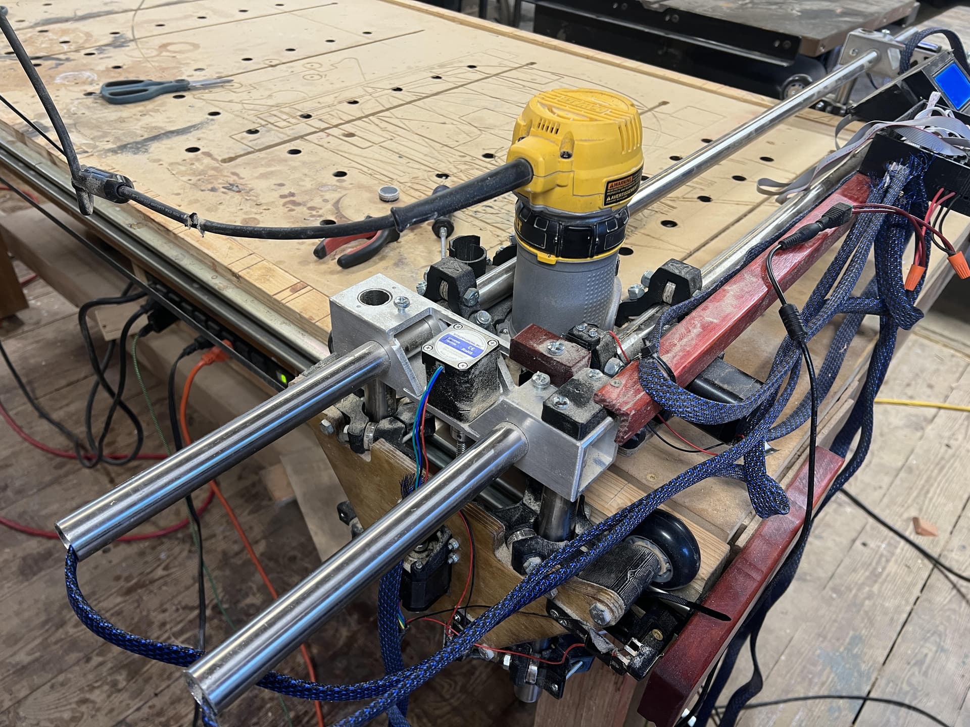
Hi everyone. Been awhile. Finally getting back to my Lowrider and have been trying to get some Vcarving going. I rebuilt the lowrider with aluminum supports for the gantry and I added all the endstops to auto home. Updated the software and everything is working as expected except for the z axis. I am sure this problem was there before I did all these changes but I cannot say for sure. The problem is that the left side tends to sag or drop during jobs. I read through a lot of the other posts and I ran into one that said that the weight should be evenly distributed so I was going to move the control box and the v1pi to the middle. I am sure this may help. I noticed though that when the zaxis was rehoming that the there were a few skips as it was raising on the left side. The coupler is quite tight. No problem there. This led me to think there was something wrong with the stepper motor. So I tried it again only this time i grabbed the threaded rod and could easily make it skip. I tried the same thing on the right side and there was definitely more resistance but still didn’t take a lot before it would skip. Do I need to replace the stepper motors or is there something else I can try? Thoughts?
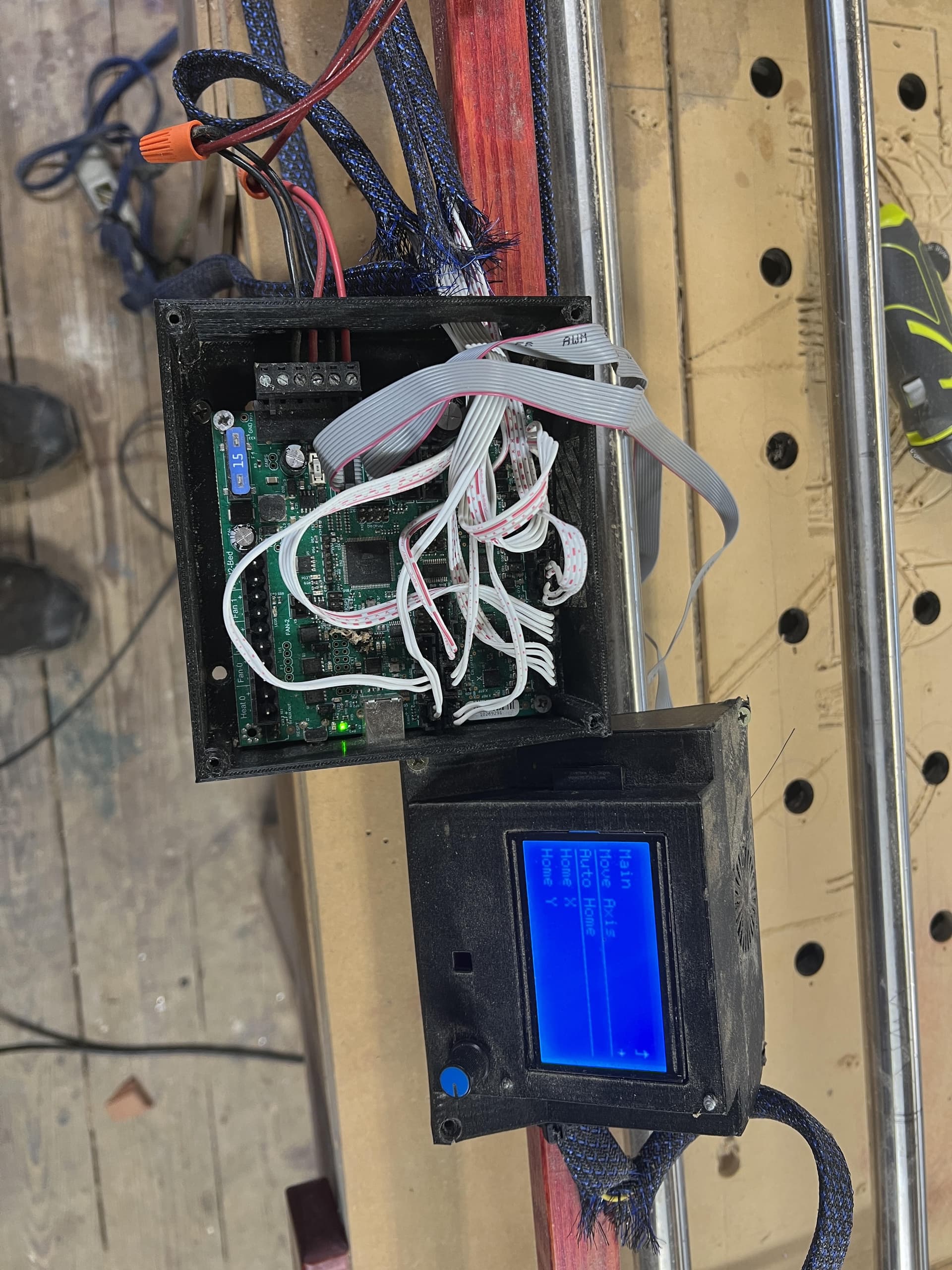
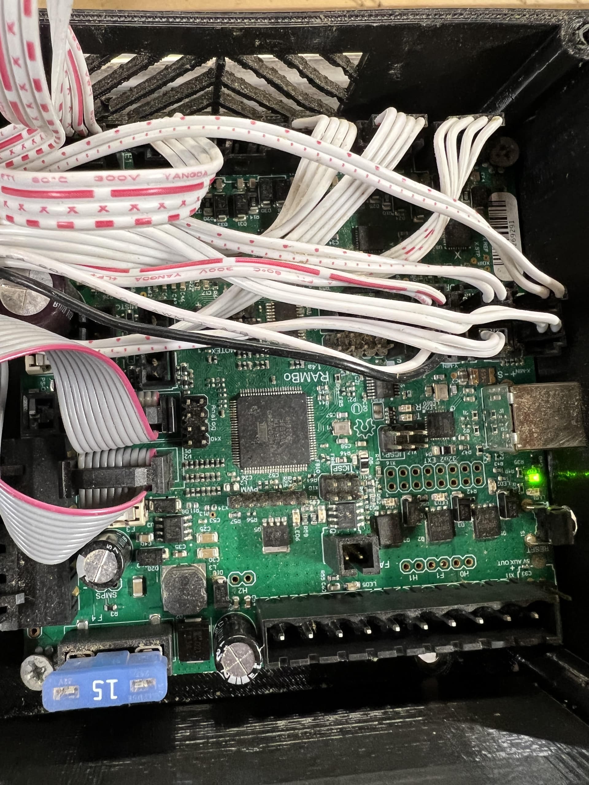
The problem is unlikely to be the stepper motor. Wiring, stepper driver current, and mechanical friction or binding are all more likely. As a first step swap the wiring for the two Z motors at the control panel and retest. Knowing if the weakness stays with the currently weak side or moves across the machine will is very helpful. If the problem moves to the opposite side, physically swap the stepper motors leaving the rest of the wiring in place, and retest. Knowing about your electronics and firmware will help us figure things out, and a picture of your control board is appreciated.
Based on forum questions and solutions, the most likely culprit is a mechanical binding or friction issue followed by a wiring issue where you plugged both Z steppers into the same stepper driver.
Thanks. Good ideas. I will try those this morning and get back to you with the results. I doubt at this point it is mechanical friction. That was my first thought and I spent some time make sure that nothing was over constrained. I agree though I should try to nail down whether it is a current issue. I will also take a picture of the board. Thanks for the help Robert!
Plugging in both steppers to the same driver is easy to do on the RAMBo board, since it has 2 motor plugs, which are in parallel on one driver. Make sure the second Z is plugged into the E1 driver. Other boards might do the same, I know that the RAMPS 1.4 board does, for example.
Well I spent 5 hours trying to figure this out. Swapped the plugs on the board and still the problems were on the left side. Replaced the steppers with some I had bought as back up. Still the same problem. When I turn off the Rambo board the left side drops right down. The right side (the good side) holds its position. There is more weight on the left side and when homing that is where the router is. My feeling is that I need more torque. There just isn’t enough at the stepper to lift the weight before it starts to skip. If I move the router towards the center the problem does not occur. I read that I could up the voltage to 24v. Is that a solution?
Here is a video of the issue.
Unpacking this statement, there are two separate things. The fact that the left side drops when you power down is a known issue with the Lowrider design. The choices to solve this issue are to block your machine before powering down, or to go to 1-start lead screws. Other things have been tried, but based on the feedback on the forum, these are the only two workable solutions.
The skipped steps are on the other hand are a different problem that must be solved. If I read you correctly, your testing has eliminated the wiring, the stepper motor, and the control board itself. There are three things I can think of to check out. The first is outlined by Dan (and I cannot tell from your picture), you do not want to use both Z0 and Z1 for the Z axis. The second is any mechanical issue. The really common mechanical issue is loose grub/set screws in the connector between the stepper motors and the lead screw. The third is the max feedrate you are feeding the Z axis. If you move too fast, you will lose steps, and the greater the load on a single motor, the sooner it will happen.
I’m really reluctant to embrace upping the torque to solve this problem. There are thousands of LowRider 2 machines using a very similar setup to yours that do not have a missed-steps problem, so there is something different about your machine that is causing this problem.
If you really want to increase torque, the most effective will be to go to 1-start lead screws. This will decrease the maximum feedrate for your Z axis. Going to 24V will not help you. Upping the voltage increases the torque at speed. That is, torque falls off as you increase the feedrate, so going to 24V will increase the feedrate you can move before you start losing steps. It does not help with slow movements like you have here. The other way to increase torque is up the current going to the motors. You risk overheating the motors or the stepper drivers if you take this step, though there is probably some head room in the V1 settings.
I am going to order the 1 start lead screw. That makes sense and I agree this is probably the way to go. In the interim I was wondering if there is a way to increase drive current from gcode? I have looked through all the settings on the LCD and I cannot find where you can change the current.
I’ve never set the current using g-code, but looking at the reference, there are several g-codes for setting current. The most likely candidate is M907. The Rambo board uses digipots, so the ‘S’ parameter should work. The values are in the range of 0 to 255, and in the V1 maintained firmware, the value is 138, which is roughly equivalent to 0.8A RMS.
I assume this g-code will work like other g-codes that modify firmware settings in that 1) you will need to execute a M500 to save the setting, and 2) once set, changes directly in the firmware by modifying the configuration_adv.h file will be ignored unless you do a factory reset. So, I think all you need to do is:
M907 S145
M500
Watch your stepper motor temps after making this change. Maybe increase this value slowly and check the temps after every change.
As an alternate, you can modify the value directly in the firmware, recompile the firmware, and reflash the board. The value is set in the following line in configuration_adv.h:
#define DIGIPOT_MOTOR_CURRENT { 138, 138, 138, 138, 138 } // { 135,135,135,135,135 } // Values 0-255 (RAMBO 135 = ~0.75A, 185 = ~1A)
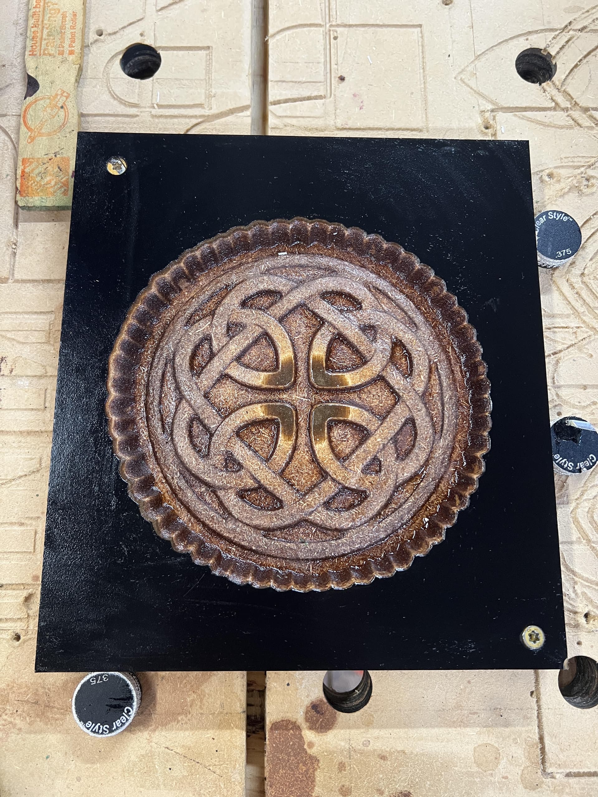
Thank you so much Robert. You have been a big help. I managed to get things going today without having to resort to any code changes. Here is something I did real quick to test it.
My sense is that there were no skips during this job run.
The fix was to go through the whole lefts side. Tighten anything that needed to be tightened, backed any bolts that may have been too tight and greasing everything that was moving that may be touching something else. After doing this I could see that the Lowrider moved very smoothly. I do plan to buy the 1 start lead screws and I will replace those if need be.
thanks for this note, it helped me fix my issues with a lowrider v3 as well, these nema17 motors can handle much more weight than I thought. Re-tighten/loosen your bolts and grease those leadscrews ![]()