Okay… here goes. I’m almost embarrassed to say this… and would have lost my shirt betting on the “fact” that energized stepper motors would hold their location… even on a slight incline. Proof, you say? You want PROOF???
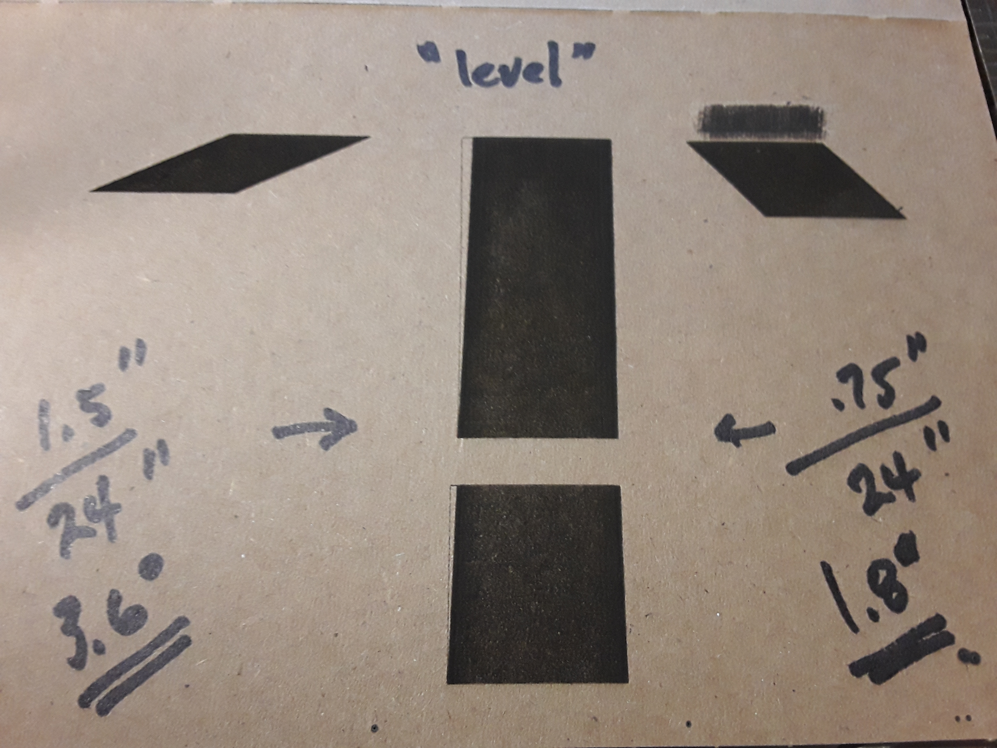
The center plot was done on a “level” (as it ever was) worktable and exhibits the skew we’ve been chasing. The top block is twice as tall as the lower block and exhibits about 2x the error. No real surprises there…
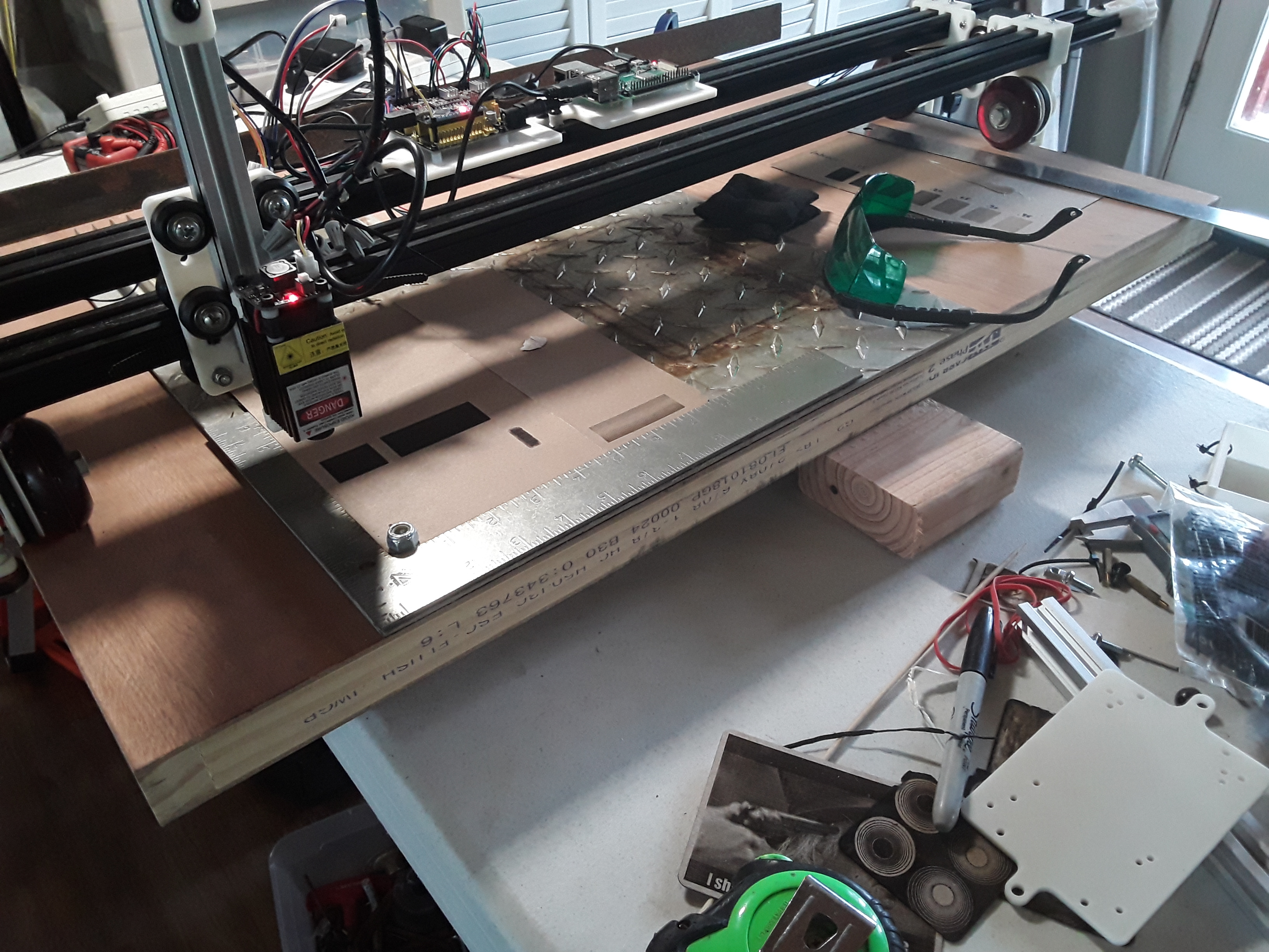
So, silly me, I blocked up the right end of the 24" worksurface with a 2x4 block (1.5" actual dimension) and ran the plot on the left.
And, of course, the right-most plot was created by blocking up the left end with the ~.75" dimension of a 1x4 block.
So, it appears the required “compensation” is simply leveling up the machine, in this case. [My sincerest apologies to those of you who asked in the beginning, “Have you leveled up the machine?”] How droll, dumb, and stupid! And then you guys were throwing around words like “quantum”, “relativity”, “microns”, “newtonian”, and “heebie-jeebies”… man, I thought I was on to something really great and mind-blowing.
Seriously, I still think there’s a mechanical problem here… but that’'s on me. I have a piece of angle iron at the far end of the machine against which I can run the gantry to park it and square it up. When I parked it a while ago, I just drove it into the angle iron and I noted that there is slippage between the actual wheel and the printed gear that is friction-fit inside it. So I need to put some contact cement(?) in there to lock the two pieces together more securely. Given that I do that, am I wrong in believing that – with adequate traction – the energized motors should be able to operate and hold their position against a slight incline?
Sorry 'bout that, guys! I really feel old and stupid right now. Give me some time to get over it and I’ll get back to you. Later.
Thanks for giving this design a good workout. It is helping to motivate me further. I have seen Ivan Miranda’s machine with tank treads & was looking at possibly modifying that or another tank tread design, but want to try the rubber band idea first since it is an easy test. It might not help, but worth a test. Did you print your wheel gears separately or in one or two prints? If not, printing them separately might help them be more consistent between them. I printed mine separately but my reason was to not have a longer print & less likely to have a failed print, but after seeing Jeff’s comments about maybe small inconsistency between wheels, printing them separately might help them be more consistent. Jamie also has a good point about making it single driven wheel instead of driving both. Not being an engineer, I didn’t really think about that to begin with. I will try a couple more things before going down the single wheel driven idea. I see what you are saying about the rubber bands picking up debris & that is certainly a distinct possibility. If I can get down to 1mm or less off during the print, it would be close enough for my current use. If this was used outside to draw chalk on sidewalk, the accuracy would probably be close enough already. I will try Rubber bands first & then maybe a TPU single tire on each side. A TPU 2 wheel tire might work as well as the tank track.
Getting a good tread pattern in the TPU might help.
Dkj, that is pretty neat. I dont think it is quite as simple as it just slipping down a hill.
Here’s what I guess is happening. When it is climbing up the hill, the outermost tread must be stretching, ever so slightly, because the leading edge is trying to pull itself up the hill. It is still in the “static friction”. But the arc length is getting slightly longer. On a downhill, the leading edge is pushing to stay where it is, so it is getting slightly compressed. You would need a microscope to see the difference.
It is very cool. And really neat that it is so freakin’ consistent.
One potential solution is to actually use a harder wheel. The error will be proportional to the amount the edge is stretching because of that force. A harder wheel would not stretch as much under the same force. You can either make it perfectly level (reducing the force to zero) or increase the stiffness. Or else, use a different kind of geometry that will not be able to stretch.
Be careful trusting Jamie or my musings. We are just thinking about it, and coming up with some creative explanations. It’s possible none of them are right
Here’s another metaphor. If you imagined a person walking instead of a wheel rolling, the person might have smaller steps when walking into the wind, and larger steps when walking with the wind at their back. The wheels are taking millions of really tiny steps on the front edge of the wheel, and their stride is determined partially by the springiness of the wheels.
Thank you for the kind works, Dave. I’m glad it’s helped motivate you… this stuff is IMHO great fun! [Except when it makes you feel stupid, of course. ]
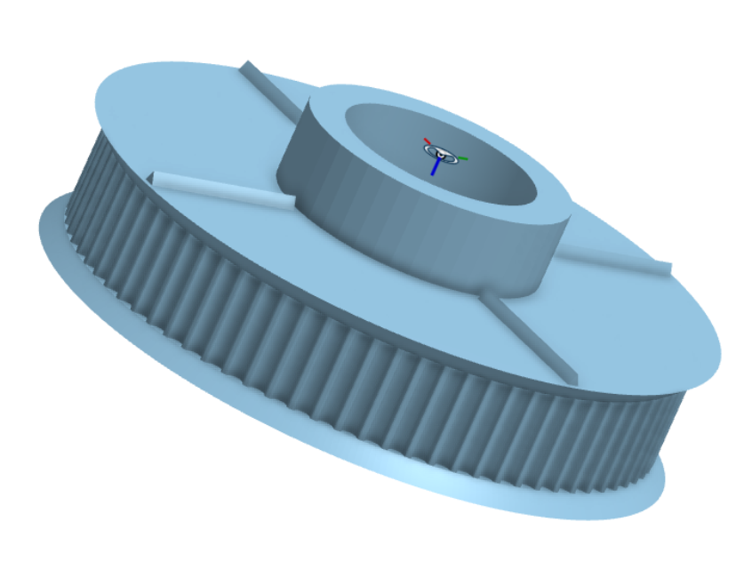
I printed each of the wheel “gears” separately… though I don’t think it would have been a problem to print two at a time. Here’s how my wheel, axle, bearing spacer, and printed gear go together and house the wheel bearings (ignore the spacers in the background)…
I’m not so sure of that, Jeff. I saw relative movement between wheel and gear on at least a couple of the wheels when against the stop. Instead of getting the normal “grinding” sound of a stepper losing steps when hard against a stop… I was seeing the gears still rolling – engaged with the belt – even though the wheel was stationary, firmly against the angle iron stop.
Regarding wheel hardness… I’ve not squeezed these wheels to check their hardness but I can’t imagine they’re considered “soft”. These are urethane roller-blade wheels IIRC and are the same wheels Ryan sells in the shop for the LR2. I had thought at one time that I might build a LR2 so I had ordered them and had them on hand when I finally got aroung to building FoamRipper and, now, this machine.
At that micron scale, I’m thinking it is some asymmetric elastic something, not necessarily wheels squishing or wheel differential specifically, but something like that. Actual slipping should not be so small and consistent.
I’d still be interested to see if it is proportional to distance or the number of direction changes. Thanks for humoring us…
Any chance one of the wheels on one side of the machine is binding? That was my problem until you told me about the wheel Spacers. Maybe one of the spacers is not quite doing its job properly?
Not sure yet, Dave. I’m running a few more tests before I tear down the wheels and try to figure out how to lock the gear and wheel together better. I think all my bearing spacers are just about right… when tightening the axle nuts, they all drew down to a distinct point of resistance, with no wobble and the wheels turned freely.
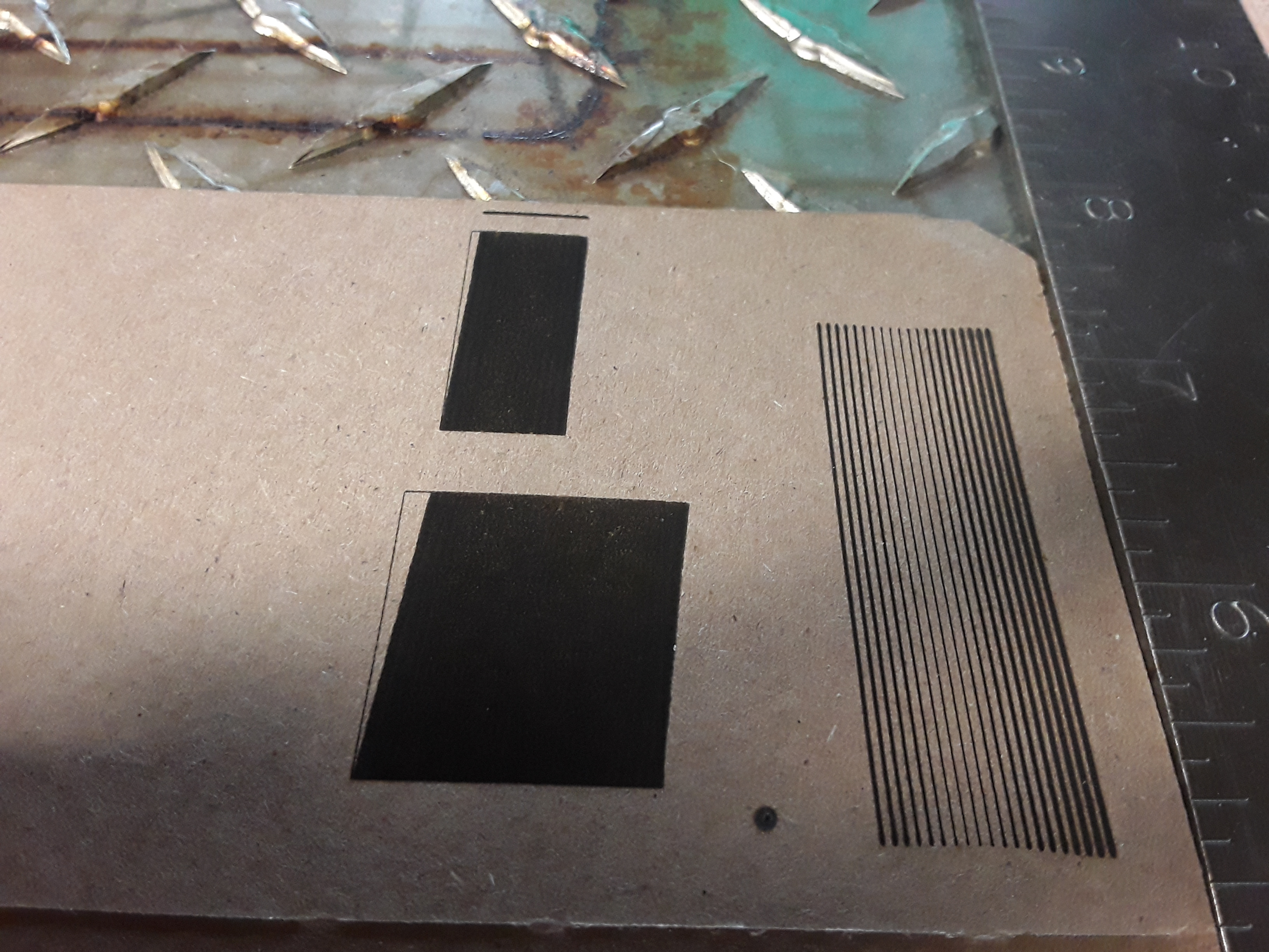
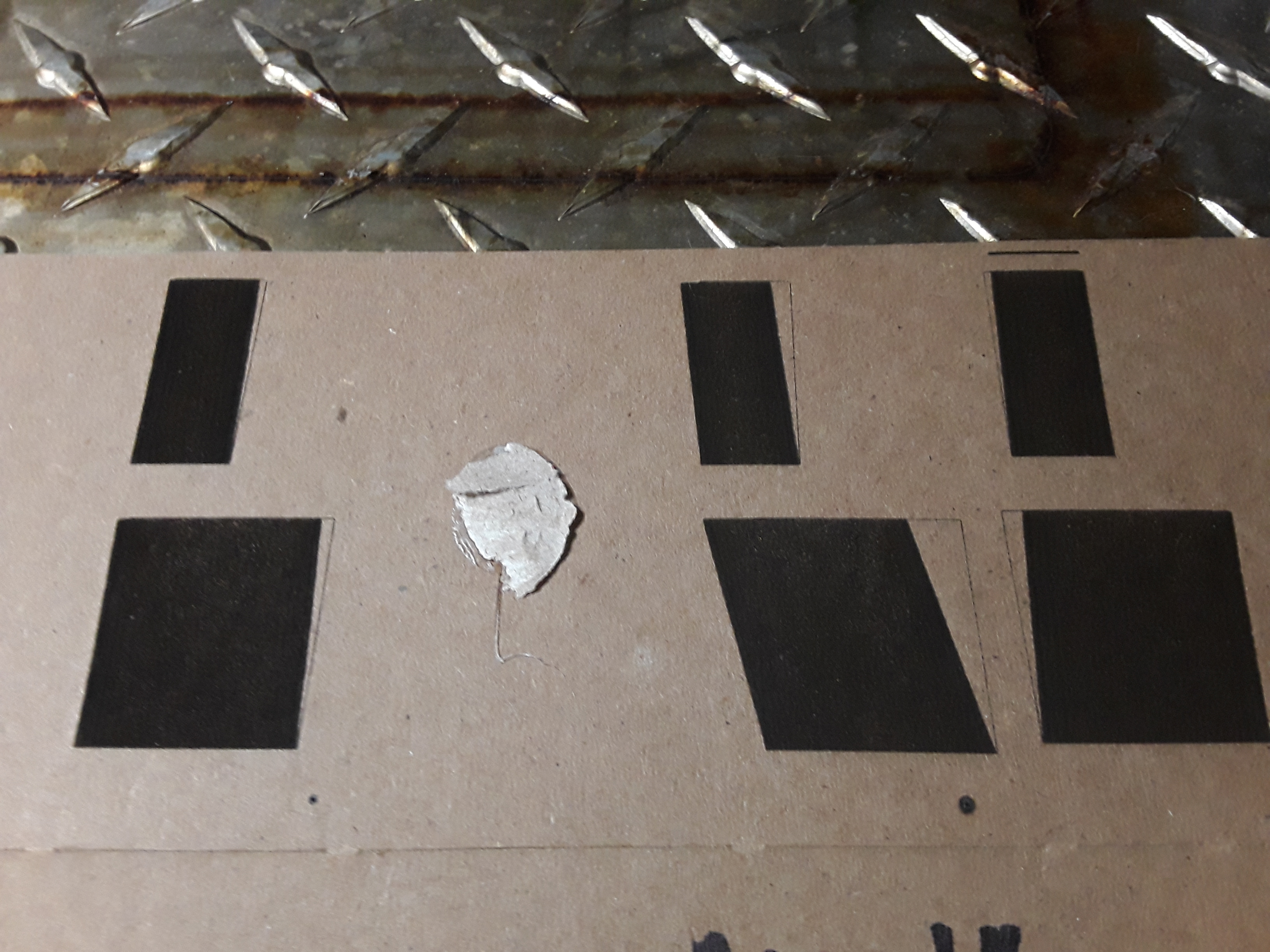
Just piddlin’ before shutting down for the evening… here’s an attempt at “skew compensation”. Note that the scanning action is top to bottom in the photo, toward the observer, and the skew is always running downhill.
So, on the far right is the exact same pattern from my last post. To its immediate left… I “shimmed” up the left side with a 1/4" (6.35 mm) thick ruler and re-ran the same gcode. It flipped the direction of skew pretty dramatically… and way over-compensated. Finally, on the far left, I replaced the left-side “shim” with simple ~1.5 mm thick craft sticks and it had the effect of lessening the over-compensation. I’m sure I could keep playing with this and start counting my “paper shims” but I think I’ve already gleaned from this what I needed to see.
What gets me is the sensitivity of this thing. If I were trying to design and build a mechanism this sensitive to something I was trying to measure, there’d be no hope of even coming close to what this thing seems to demonstrate.
My worksurface is 24" long in the direction the tractors are rolling… and is the hypotenuse of my triangle. If my math is right (and it’s probably not!), the change in angle with the 1/4" shim is only 0.6 degrees… and only 0.14 degrees for the 1.5 mm craft stick. I would expect the ripple effect of a butterfly flapping its wings on the other side of the globe…
This fine adjustment stuff is straining my tired old brain. So I think it is time – in the morning – to tear the wheels down, get the wheels and gears locked together, and remove them from the list of suspects.
That is really neat. Looks like you need about 0.5mm less.
I really like the idea of the wheel and the table causing this effect. But having a neat idea doesn’t make it true. I’ve been thinking about the gear to wheel interface and how that could cause it.
It can’t be overcoming static friction. If it did that, it would have “big” jumps and then smaller ones and I don’t think it would be consistent. So it can’t just be slipping. But what if the outside diameter of the gear was slightly smaller than the inside diameter of the wheel? I’m imagining it tumbling, like laundry in a dryer. When it falls down, if there is a longitudinal force from gravity, then the amount it would skip while rotating might be slightly different. So as it is coming down it is almost completely in lockstep, because it is falling such a small distance. But it rotates a small fraction of that distance separate from the wheel as it is falling.
An interesting experiment would be to make a mark on the wheel, the table, and the gear and then run it until it is off by a big enough amount that you can tell what slipped. Maybe put the 1/4" stick back in to exaggerate it.
I don’t think it would hurt to glue the gears in. It doesn’t have to be strong. It could be a drop of CA glue or even locktite.
Added small knife-edged ribs on the flat surface of the pulley that I think will “bite” into the firm (not soft), very slightly concaved, side of the wheel. [These particular wheels look as though that slight concavity was shaved into one side after the fact… reason unknown.]
I’m so shaky that I always make a giant mess with any liquid/glue/paint and thought this the might be an easier but adequate (and reversible!) solution to my slippage…
What do you think about completely printing the wheel on the cog? There would be no flex there. Of course, there will be more chance of overcoming static friction between the printed part and the table.
And, I’m sorry you’re having shakey hands. That must be frustrating.
 ]
]