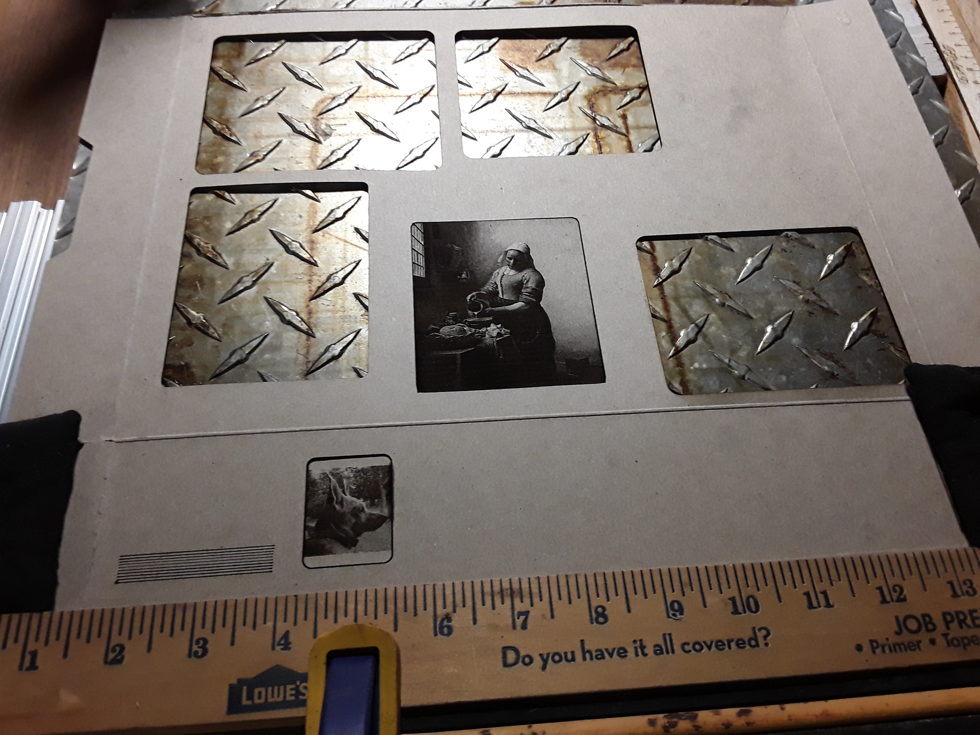
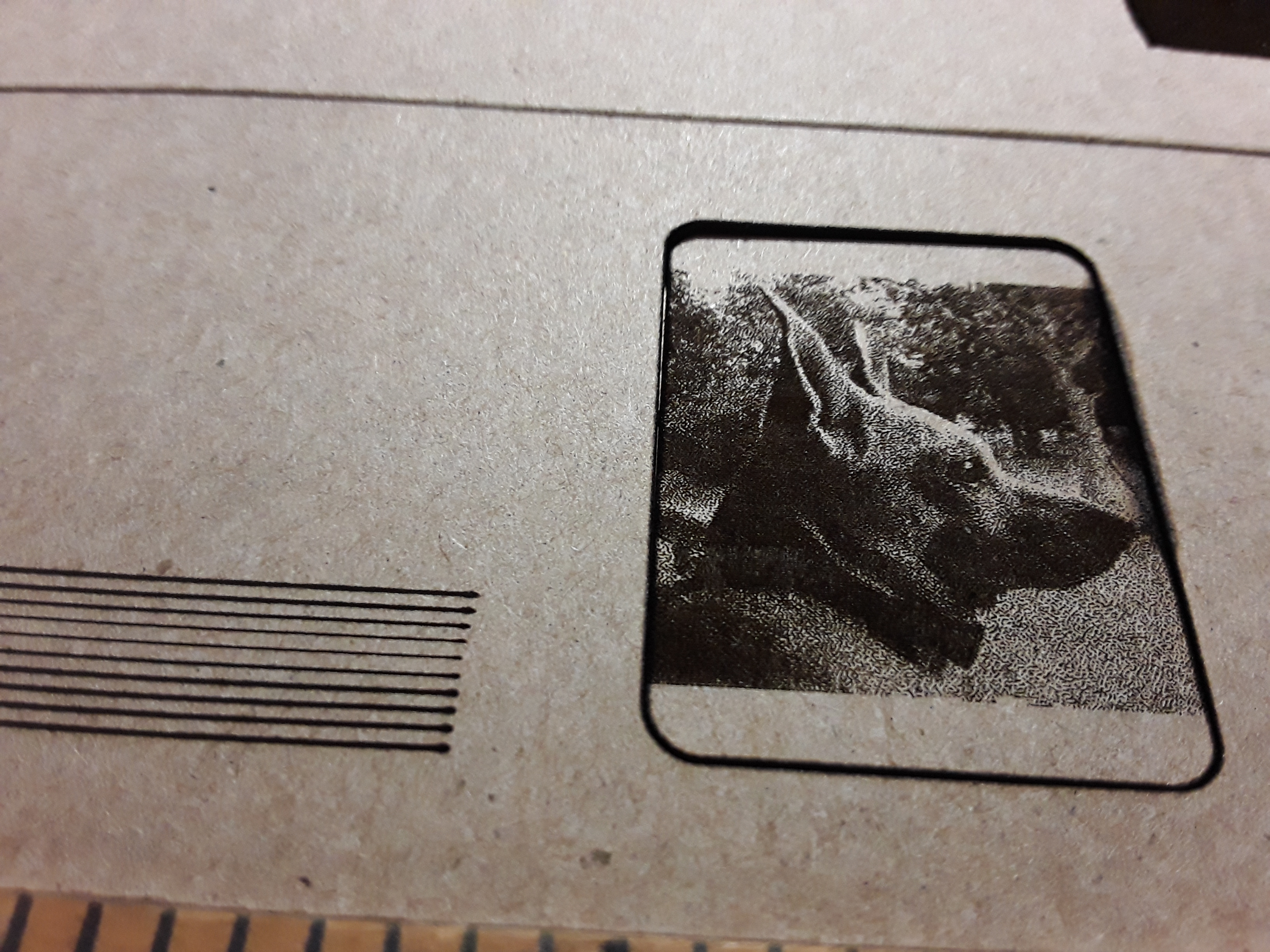
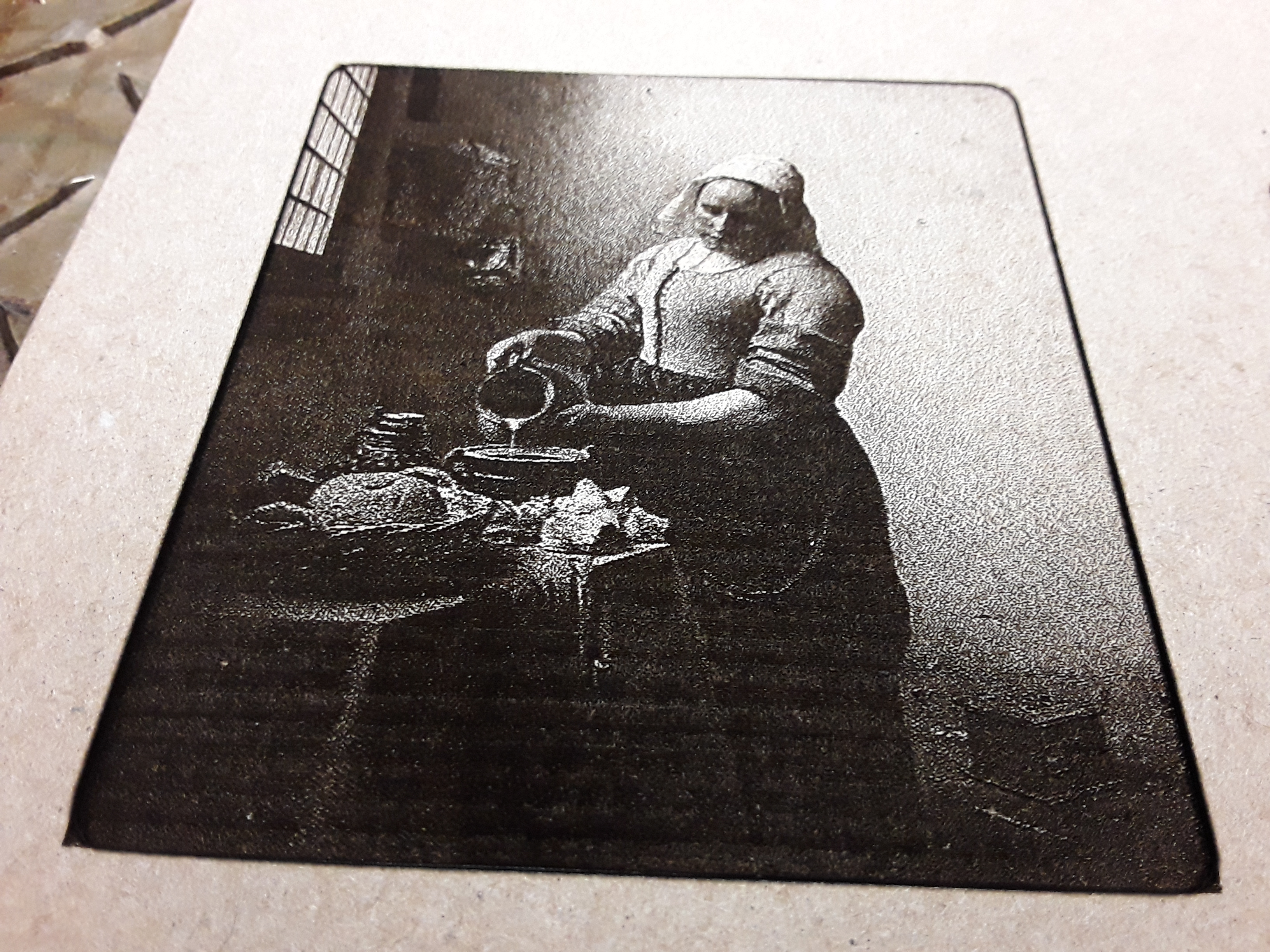
I personally like a 3-axis capability… even with laser. A real Z-axis allows you to easily adjust the Z-axis for ABSOLUTE BEST FOCUS – I use Ryan’s focus script all the time! – which is necessary for the smallest spot and finest line. It is also a requirement for the absolute nicest photo-quality engravings… like these done by @Bulldog, over on the LB forum, on ceramic tile with just a 2.5W Eleksmaker laser!
I don’t see the point of a third axis myself. The focus doesn’t change when engraving, it is no harder to set the focus by turning the focus ring than driving the whole laser up and down providing you have a decent collor on the focus ring. If you are cutting 6mm thick wood that is a different matter, some focus adjustment may be required for best cutting results but that can be achieved by pausing the program and manually refocusing using low power. I think having any Z commands in your gcode can cause problems with burning as the laser stays on while the Z command is processed so I think better off without. Horses for courses!
I have probably a month or so to think about this. My wife said I can order one as a reward when I replace the decking boards on our two decks. Guess this will get me motivated to finish them sooner.
I think it must be the same basic machine Edward Chew ripped off with his TimSav machine as well… though he enlarged it to cover the extents of A4-size(?) foamboard and adapted it for the needle-cutter. He put a servo-driven Z-lift on it for the needle-cutter and added a little outrigger “landing gear” to prop up the far end of the skinny axis, for consistent depth of cut control.
Thanks for the pointers to these 2 designs. I might have to look at one of these designs & just buy the laser components since I have some 1 meter 2040 & maybe a 1 meter 2020. I like the wheels on those versus the cheaper Chinese ones. This way I could use the components I want.
After looking on thingiverse for some CNC engraver ideas, this design https://www.thingiverse.com/thing:4332724 looks similar to these designs & fairly simple parts. I have enough V-Slot for it. The parts he made on his CNC look like they could also be 3D Printed. He is using a 400mm length of 2020 for the arm. If I cut that main part out of Aluminum on my CNC, do you think I could go to 500mm length arm? 400 is probably adequate though. I could always go to 1000mm on the 2040 axis.
That looks good. I built my second one to cut balsa from 4"x 36" sheets, my x axis was 1.20M long and the Y was only 25cms. The 2040 X axis can be as long as you like! The longer you make the unsupported cantilever the worse the sag will get as the mass of the laser moves outboard…keep it as short as you can. The wheels on the carriage will deform adding to the sag over time so an adjustment mechanism should be utilised to get the perfect position between play and rolling resistance.
I have uploaded my version stl’s if anyone is interested. cantilever laser machine stl.zip (1.1 MB)
Thanks for the STL files. I had already taken a look at your .123dx files yesterday. They will import ok into fusion 360. I will probably use the ideas from the 3 different machines that I like best to piece together my machine mostly so I can use any of the spare parts I have. I do like using the short 2040’s for the ends, although 2060’s might be a better height. I will use wheels for the x/y axis instead of the linear rail in that one design since I have some spares. The design I referenced has a main plate that is 105mm wide whereas yours is only 54-56mm wide. His seems pretty wide, but maybe that helped with him cantilevering further since it spreads the load wider? He does loose some cutting width with the wider plate. I probably won’t make the cantilever anymore that 400mm, but might use 300mm to start with as 400mm seems like a lot. I did see in the TimSav design that dkj4linux mentioned had a wheel at the end of his V-slot to handle the support of that long beam. How much cutting width do you have with the 250mm length? Seems like you will loose 60-100mm.
Here is another interesting design that looks like the Corexy belts are helping support the cantilever.
Actually lost about 140mm in all…100 at the root and 40 at the tip…but it was designed for a specific sized workpiece…balsa wood comes 100mm wide.
Any loss of cutting length from having a wider frame is easily made up by having a longer 2040 (or 2060) beam and I would think a wider frame has to reduce the chance of side to side play.
When I looked at the links from my build log the other day the second link wouldn’t work for me…if you need access to any missing files let me know.
I like the coreXY, that is a nice idea…although it does loose the beneficial counter weight of the two stepper motors hanging off the back of the ‘boom’. Linear rails are of course going to be better than delrin wheels but at a significant cost hit. Will GRBL handle coreXY? I don’t think so, so I guess it is running Marlin - you can just make out the extra burnt edges to the logo he was engraving…nice logo too!
I am sure you will end up with a better design by taking the best bits from many designs…and it is fun at the same time.
Maybe I should start a new build thread for my mish mash design so we don’t stray too far off tangent of dkj4linux thread? I am initially assembling all your parts in fusion 360 so I can understand it a little better. The other design does have 2 motors counter balancing that beam, but connected differently than yours. Not being an engineer, I am not sure which design will support longest reach best? I would not use linear rail, so my reach would be less on his design than what he is getting. His design has the part main_carriage.stl file connected to the 2020 cantilever beam around 66mm out on the bottom and the other connection about center of the 2040. I don’t have anything specific in mind for engraving with a laser, but would like to have it the best compromise of size to function. 2040x500mm for main beam & 2020x400mm for cantilever beam is probably good enough for me to start with. I might go 600mm for main beam. I will probably use eccentric spacers for all the wheels instead of the way you have it if it fits into design easily.
I did find all your parts in that thread as well as the assembly file.
Go for it! I’m not a mech engineer either so I am not claiming my design is mechanically ‘best practices’ so please feel free to take what you want and modify it… I bet you end up building more than one
If you use eccentric spacers on all the wheels might you end up with a cantilever arm out of square with the main beam?..might be best to just have eccentrics on one side only.
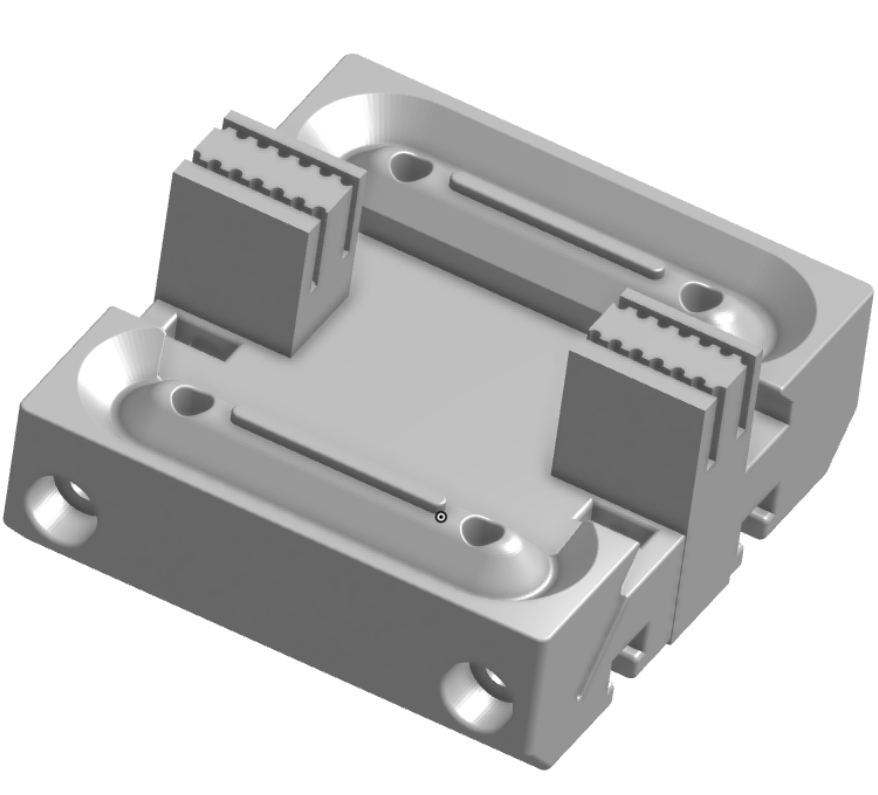
I’ve enjoyed playing a little with miniFR but am not happy with my Z-axis. So started looking around on Thingiverse and, remembering how impressed I was with a printed screw-drive linear slide by 3DPRINTINGWORLD, I found that he’d done a belt-driven slide as well. I printed it and put it together only to find that regular GT2 belt was a bit stiff for the slider channel and really didn’t attach securely to the carriage. He printed his belt with TPU, which I’ve never tried… and, on a lark, decided I should. Ordered Overture TPU, got it the next day, and actually managed to print a few belts on my MK3S. But this particular TPU, while flexible, is also quite elastic… and it really skipped teeth easily. So I decided to see what I might do to the carriage to enable regular GT2 belt to be used. I used FreeCAD to create a STEP model of the carriage and then imported that into Onshape, my CAD of choice. I plugged the posts and cavities where the TPU belts fastened and then created toothed channels for the GT2 belt.
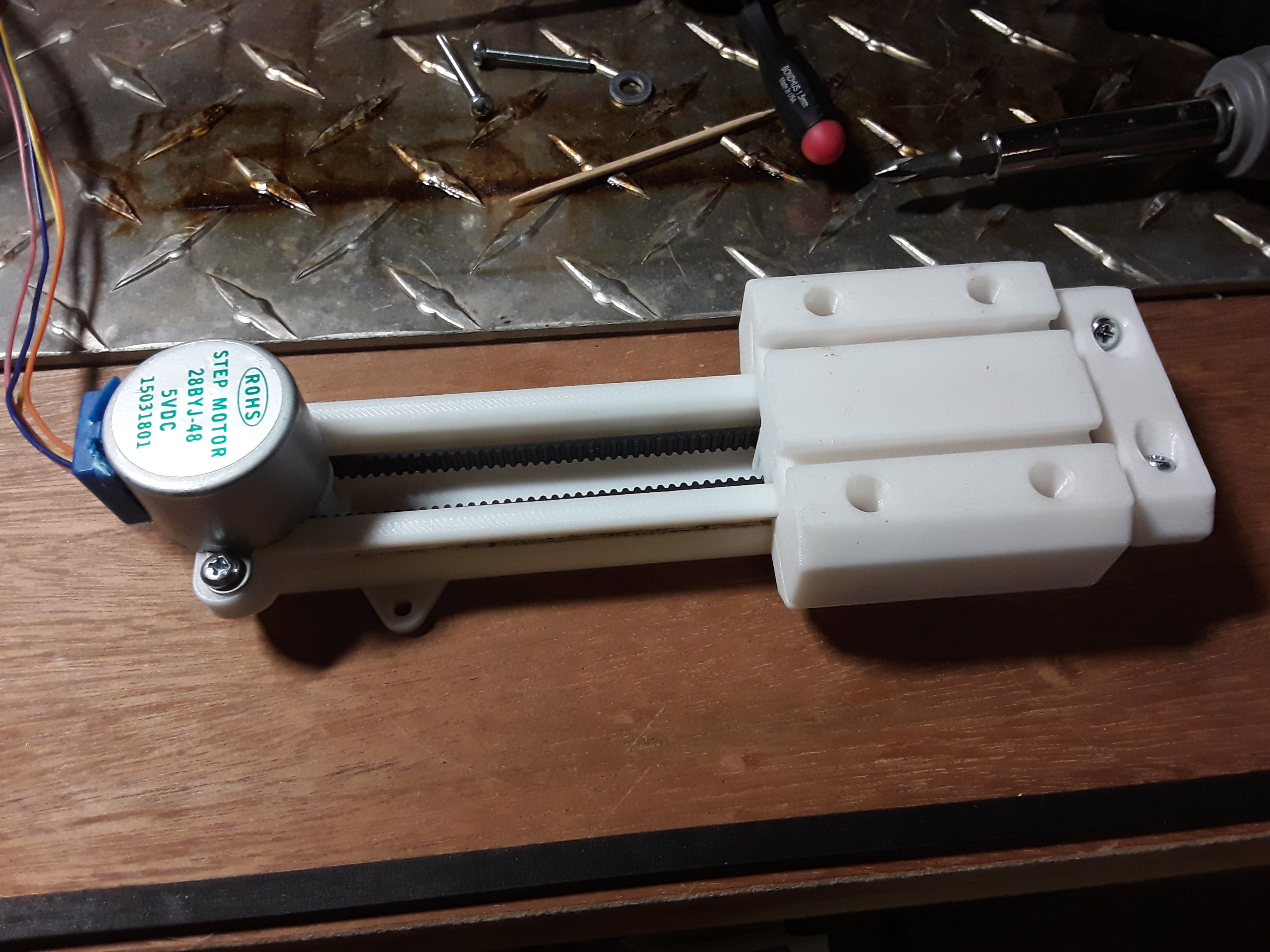
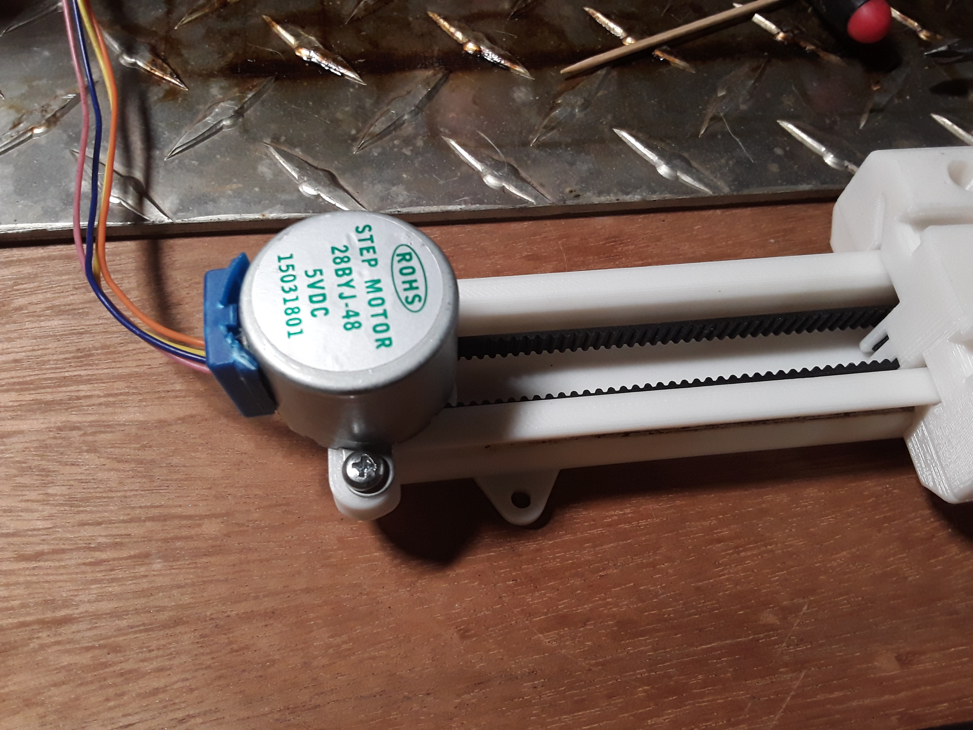
So I rebuilt the slide with GT2 belt and now it seems much more robust and positive… and the little 28BYJ-48 is surprisingly strong when set up as a bipolar motor. That’s my bench vise (a couple of pounds) riding back and forth over 70mm range…
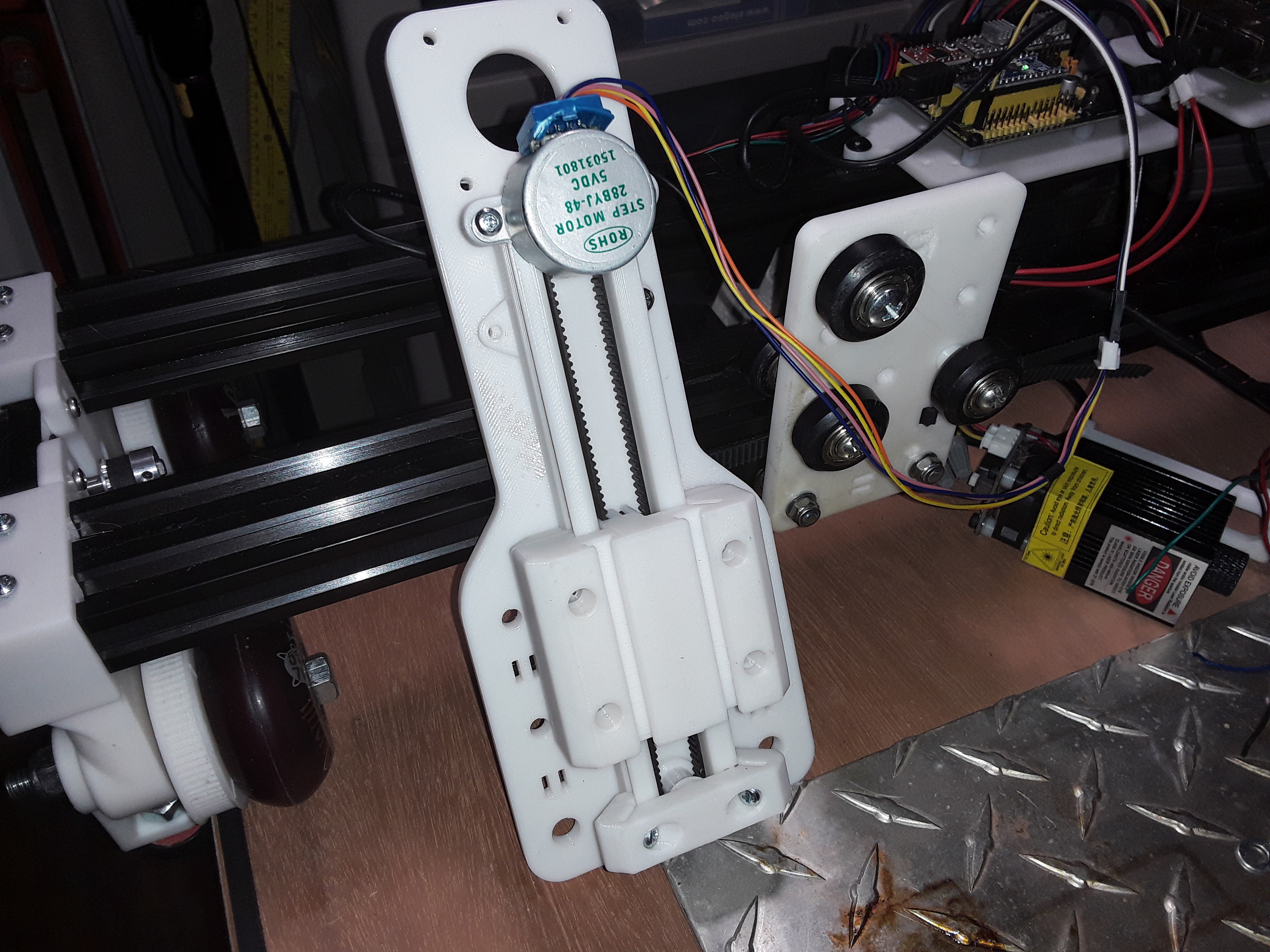
Satisfied that the slide looked like it was gonna work, I took a first cut at coming up with a new X-carriage to mount the slide on. The slider is noisy with all the BB’s recirculating in the race tracks with no lube… but of course this machine isn’t going to be doing tons of Z-moves anyway.
The first-cut X carriage plate will mount the “stock” slide but I can already see that I can open the end of the slider rail, remove the small stepper motor, and mount a small NEMA17 and drive pulley just above it and drive it with a more conventional stepper motor…
This assembly will replace the carriage plate in the right background. While I was at it, I also widened the “wheelbase” and placed holes for wheels/axles for either 2020 or 2040, should I ever decide to beef it up a bit more.
Looks like your are conquering the Z-axis problem. When you get it working for a nema17, I wouldn’t mind looking at the design. I really do need to make that mod to the 28BYJ-48 motor, but have a mental block against it at the moment.
I printed several X-carriage plates before finally getting all the wheel and belt openings properly located, and X-axis rail modifications made, to accommodate a wider “wheelbase” and 2040 spacings…
Movement in all three axes… Z-axis BB-bearings are noisy but movement is relatively smooth
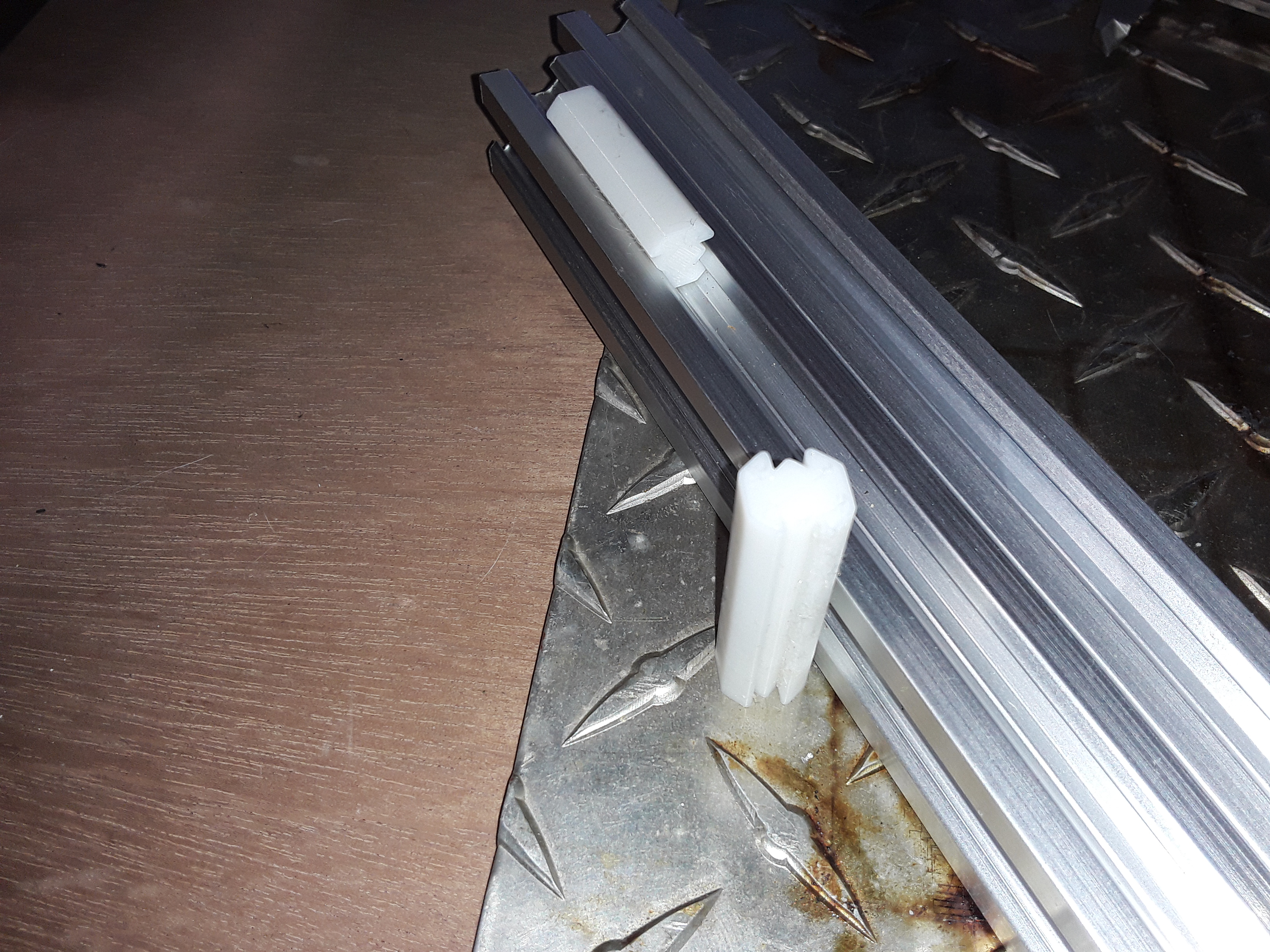
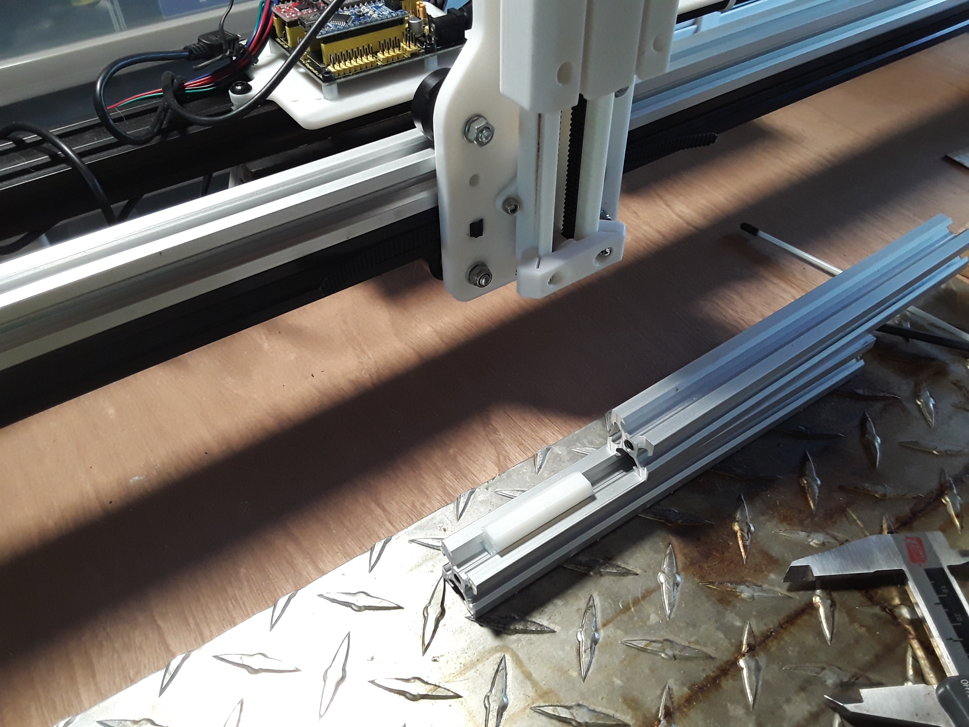
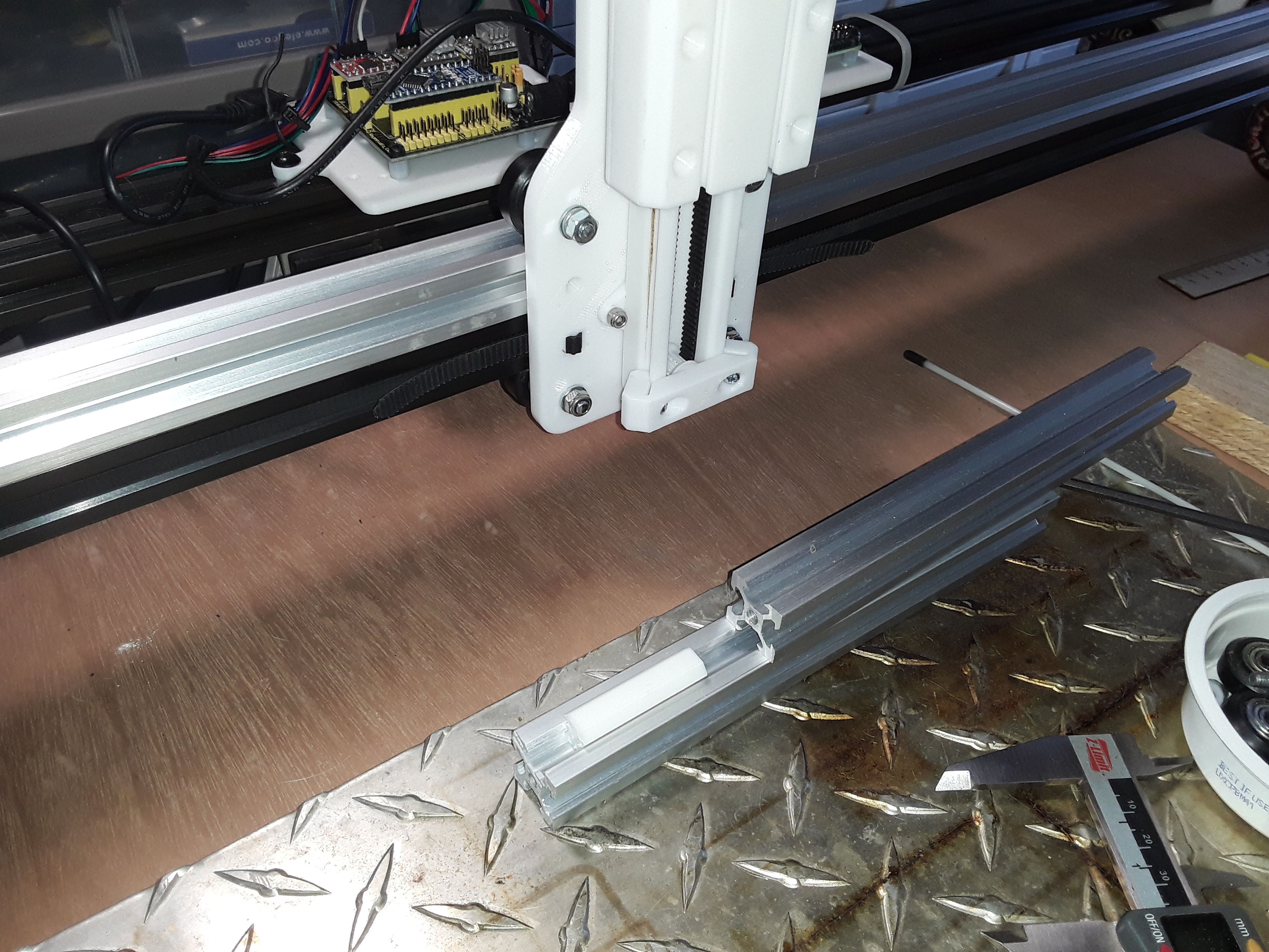
As I happened to have a length of silver 2020 already cut from the TimSav I dismantled after “retiring” the TimSavX2 hot-wire machine… it fit pretty-nicely between the tractors and on top of the existing X-axis extrusion. So I printed some “joiner” pieces to lock the V-slot together along their length and added it to the existing horizontal 2040 X-axis rail…
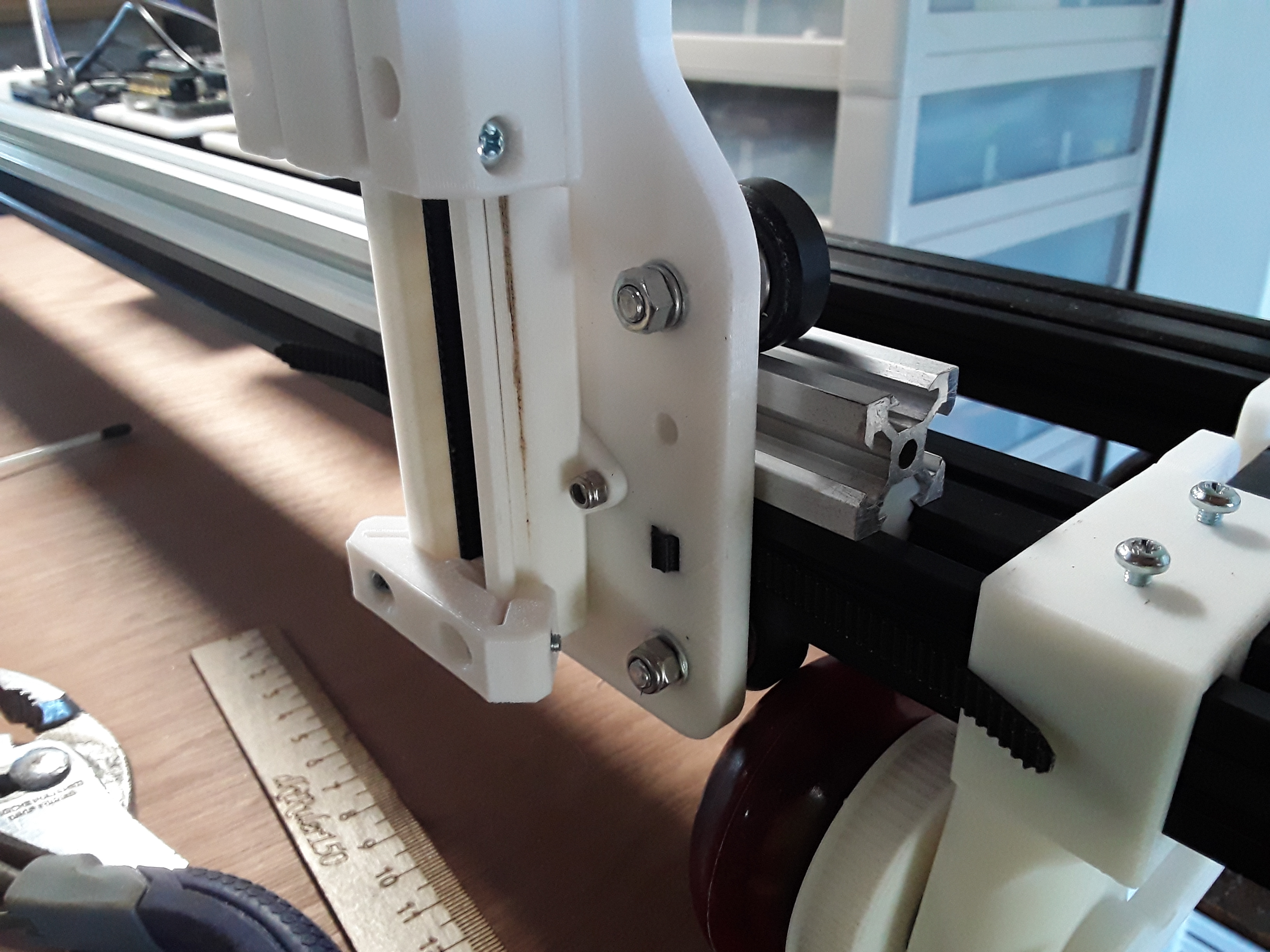
And now, the X-carriage wheel spacing is for 2040 (vs 2020 before) and, with eccentric spacers on the lower wheels, it is much more smooth and stable than before…
I could, of course, do away with the need for the added extrusion by re-orienting the front X-axis rail from horizontal to vertical but I didn’t want to take time to modify and reprint the tractors right now.
Next I need to mount the laser onto the Z-axis and, hopefully, I should be back in business.
Oh, my! Somebody… please help this fella find a cool spot in the shade…
Seriously, thank you for the kind words… and you’re welcome. I’m just doing and sharing what I love to do and I’m thrilled there are folks like you who are appreciative. Thank you!
")