Is there a way to turn off fan voltage on startup?
I’m using a fan pin for pwm and it works. I just need to disable the voltage on startup as it defaults to 10.3 volts on startup.
It should be off. Are you just getting a tiny little pulse?
It’s not off, I used multimeter on the PB5 pin of the SKR2. On bootup, it gets 10.3 volts. I have my laser PWM going to it. It works fine, I just need to disable the 10.3 volts on bootup.
Sorry I have never used an SKR2, but no fan should be on at boot up and 10V is a very odd number it suggests it on 80%. Sounds like a firmware setting.
I suggest using a different fan port and changing the laser pin in the firmware.
All fan ports default to 10.3 volts on bootup. Just checked each one.
There has to be a way to disable the voltage on bootup. Looking into how the toggle switch works and maybe I can create a method to call on bootup.
On power up, it is not yet under firmware control, so you’ll get what the hardware does. It’s hard to change that. You might need to just put in a delay circuit so that the firmware gets a chance to boot up before the pin means anything to the tool. You could maybe use a gate chip so that it needs (for example) the ENA pin to be live on one of the stepper drives. That would mean that the tool cannot turn on until the stepper motors energize.
Also, I’m pretty sure that all of the (+) fan pins get Vin all of the time, and that the switching takes place on the (-) pin. The fan doesn’t care, but your tool might…
2 Likes
You are correct. I gotta figure something out then. Maybe will have to get a new laser with actual 5v TTL and not 12v.
Where are you measuring ground when you are getting 10.3V? The positive side of these is always tied to Vin, the negative is what gets toggled.
1 Like
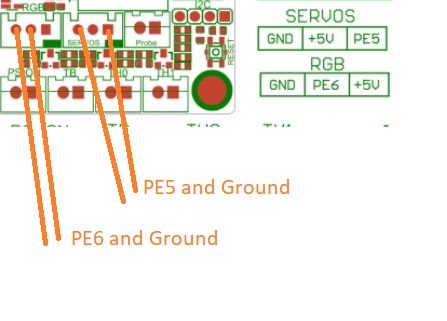
That is not your problem. Your problem is your laser is expecting a positive going PWM pulse and all of your fan outputs, as Dan says, provide the PWM by chopping up the ground because they all employ N channel FETs. You will continue in a world of hurt until you manage to rectify this basic problem. Either use a direct PWM output from the MCU (seeing as the SKR v2 does not have a dedicated output for laser PWM your best options are either PE6 (currently assigned to RGB) or PE5 (currently assigned to servos),
other than that you will be directly soldering onto R93/R94 junction to obtain the fan2 PWM signal before it gets to the Fan2 mosfet (not recommended)
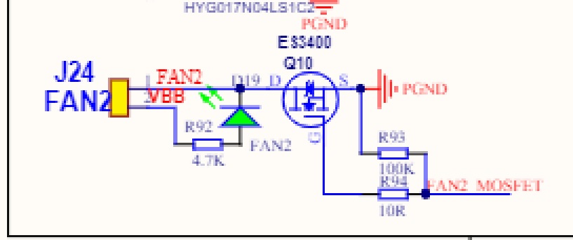
…or invert the fan output from the FAN2 socket J24 using an opto-isolator or transistor inverter. See Issues getting laser configured properly - #17 by dart1280
An oscilloscope will be of great benefit checking for a proper PWM signal
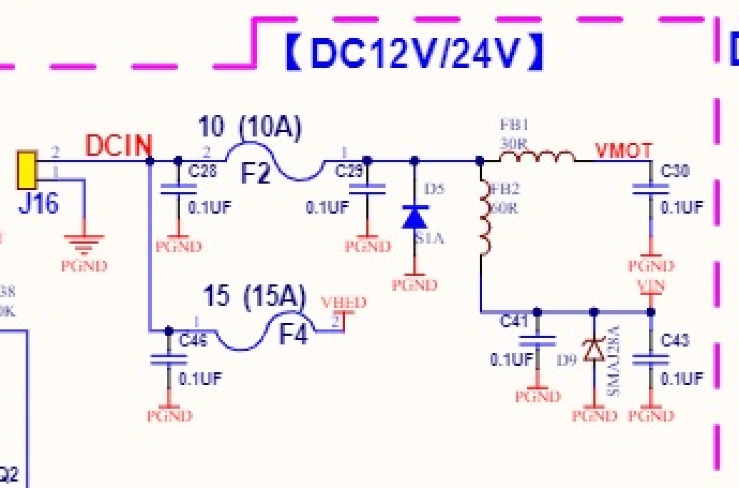
Your 10v isn’t right. the FAN2 socket J24 has VBB on pin 2, this should be the same as VMOT , this should be the same voltage as DCIN. Check the voltage at F2, if that is 12V suspect a faulty Q2 or U5

2 Likes
I was measuring ground going to the PSU. I left the ground going to the fan pin unhooked as the toggle didnt work anymore.
yeah, my problem is that this laser isn’t a 5v PWM laser which was incorrectly advertised.  I tried using the servo, it didnt power the laser.
Ok. Then that pin will be the same as your motor voltage, all the time. It sounds like your motor voltage is 10.3, which is surprising. But that is a red herring.
What you need to measure is the voltage between the positive and negative fan pins. They will tell you what the laser is seeing. The positive fan pin is always tied to +V.
The reason is, the components to turn on and off a ground are cheaper (for the same amount of current) than parts that can toggle the positive side. Or, the other way to look at it is that parts that can toggle the ground are more powerful for the same price. Every printer board does it that way.
So I bought a new laser from somewhere else which was advertised to have 5v PWM and connected it to the servo with the ground from servo going to my PSU (that’s also where the ground is from the laser). It ended up working… But a weird thing I’m seeing is the SERVO outputs 3.3v. I’m guessing this is because the SKR2 is a 3.3v mainboard. Will this impact the laser power in any way since it’s not seeing a full 5v?
Here’s my config_adv.h
#define LASER_FEATURE
#if EITHER(SPINDLE_FEATURE, LASER_FEATURE)
  #define SPINDLE_LASER_ACTIVE_STATE    LOW    // Set to "HIGH" if SPINDLE_LASER_ENA_PIN is active HIGH
  #define SPINDLE_LASER_PWM_PIN PE5  //SERVO (Rightmost Pin) on SKR 2. Refer to SKR USER Manual for Picture
  #define SPINDLE_LASER_ENA_PIN PB3   //HE0 (top most pin).

  #define SPINDLE_LASER_USE_PWM                // Enable if your controller supports setting the speed/power
  #if ENABLED(SPINDLE_LASER_USE_PWM)
    #define SPINDLE_LASER_PWM_INVERT    false  // Set to "true" if the speed/power goes up when you want it to go slower
    #define SPINDLE_LASER_FREQUENCY     1000   // (Hz) Spindle/laser frequency (only on supported HALs: AVR and LPC)
  #endif

some code inbetween here blah blah

 #define LASER_POWER_INLINE

#define LASER_MOVE_POWER
The way they often work with 5V PWM in is that they actually care about the amount of time the output is on. 3.3V is more than 2.5V, so it usually can accept 3.3V PWM input.
Gotcha. Thanks to everyone for all your help!
Just use a pull down resistor. Simple solution. It’s a 10K ohm resistor between the + and - pins for your laser. That will prevent the laser from Turing on during boot up.
Also you don’t have to stick with that positive pin. If you want to find a positive pin of another voltage then go for it. Just use the fan negative as your control pin.
Unless you plan to power the laser through these pins. But that’s a rare situation. I assume you are just trying to get a control signal. I’ll leave it at that for now.
Edit: corrected the 1k to a 10K ohm
This thread may cover it all in detail as well.
It already has a pull up (on the ground pin) 4.7kOhm through an led on the board. Another resistor across the fan port won’t help.
Not on the servo line it hasn’t Jeff. An additional pull down resistor between PE5 and ground may, or may not be needed, it all depends on what the MCU does to that data line during boot, if it leaves the pin floating then the laser may fire… or it may not. Try it without the resistor and remember the fix if the laser does fire up during the boot sequence. I suspect it will be ok because if it did float a servo would twitch during boot and I doubt that would be acceptable to the designers.
We talking in circles. Aaryn said to just use a pull down resistor. Iced hasn’t said anything about the servo pin shooting the laser at startup.