New chain links are definitely much better and move smoothly. I’m hoping to get back out to the garage this evening and continue assembling and wiring everything everything up with plans to get the first Crown drawn tonight if possible.
1 Like
When I printed my chain links, I printed them in the same orientation and they were a little curved over the whole length. I wish I would have printed half of them backward to negate the small errors each part had.
1 Like
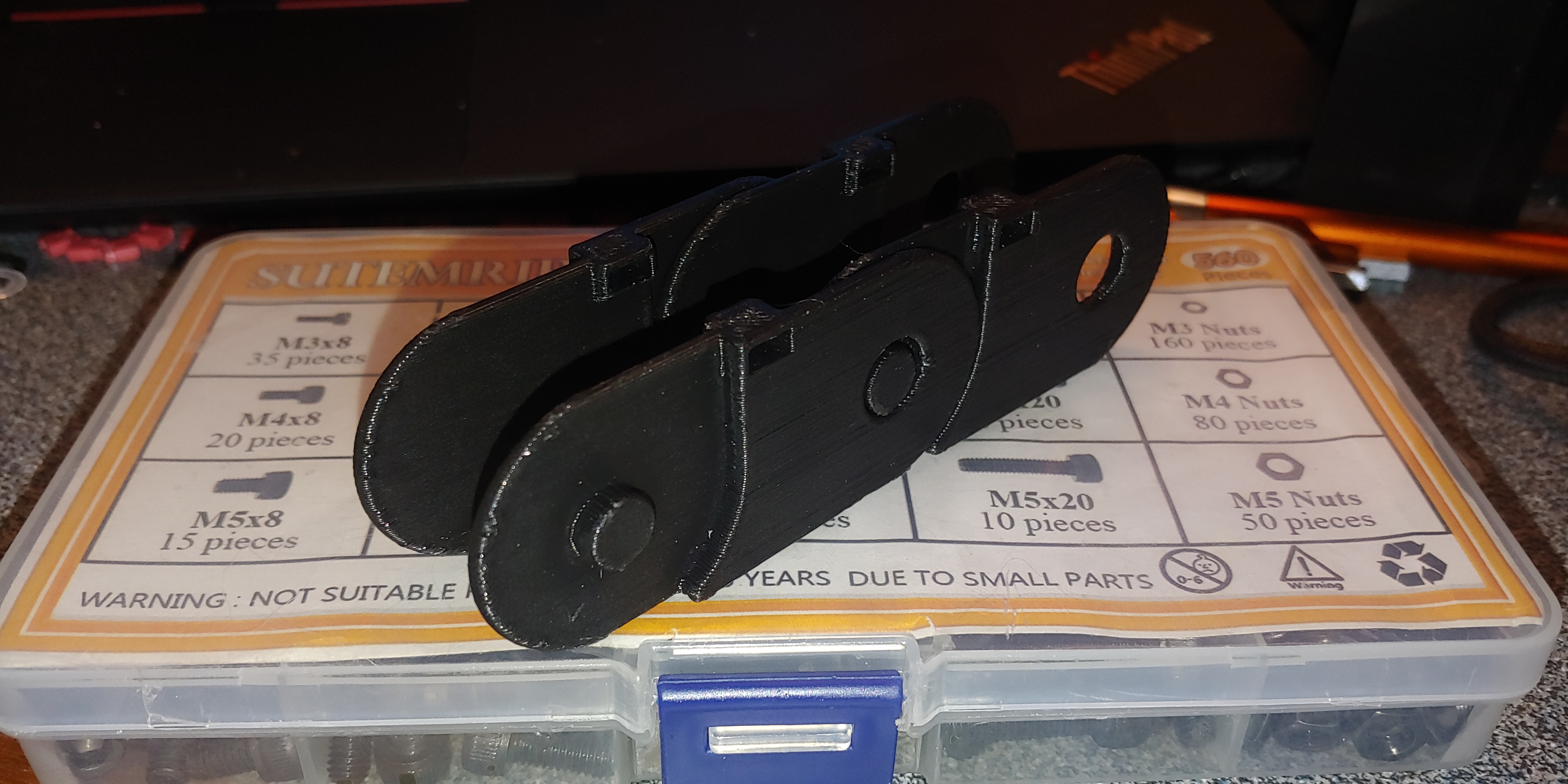
I am printing each of these separate from each other, and they just snap together. The chain should be perfectly straight when done, but allow a little bit of play.
My design process in Fusion 360 was to create one entire side, then mirror it in 3D space and then extrude the connector on the bottom to tie the two pieces together. Now I can just print as many links as I need for whatever, and can scale the width of the link to make room for more cables, or scale the whole link up or down on a whim for whatever size I need.
Unfortunately, I had a print failure caused by a plugin in my Octoprint that kept telling me I was out of filament, so my batch of 20 only made it about 35% of the way through. I fixed the error, and have 6 links printing now so I can get them in place this evening and test the overall motion in the top cable/hose support.
My point was, if there is a skew to your printer (X is maybe 90.1 degrees from Y), then each part will have a small curve to it, and that will add up when you print 1m of them. If you just print half of them pointing the other way (rotated 180 around Z) then the skew will be +0.1 on one part and then -0.1 on the next, and you will get a perfectly straight chain. I didn’t do that. And even though my printer was as square as I could measure it, the results were a gradual curve.
1 Like
That makes sense. I wasn’t thinking of it from that aspect. I’ll have to check it out once I get a longer chain built. I’ll be printing off enough for two chains, one for X and one for Y, so I should have plenty of links to mix and match.
1 Like
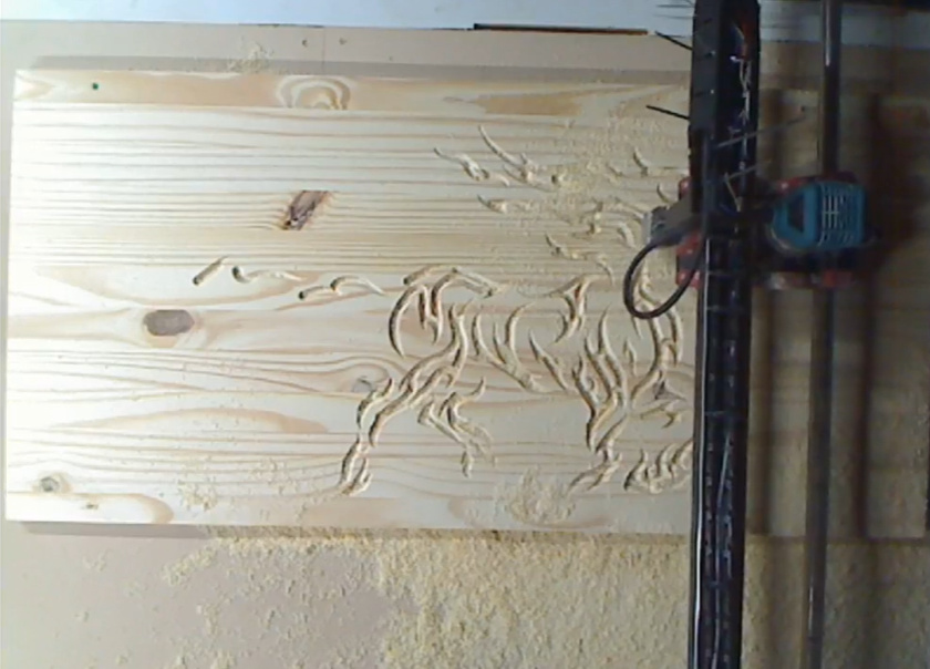
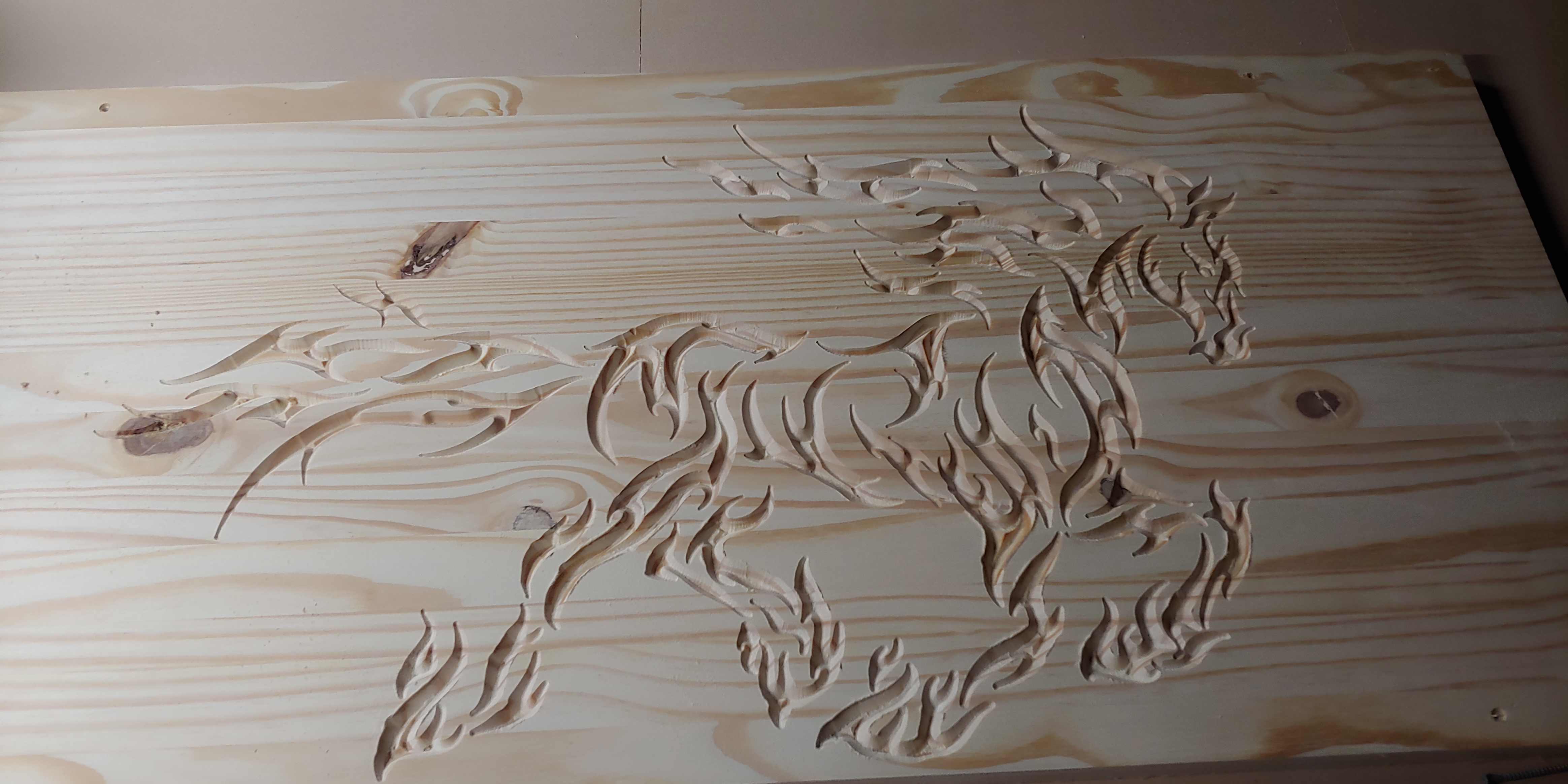
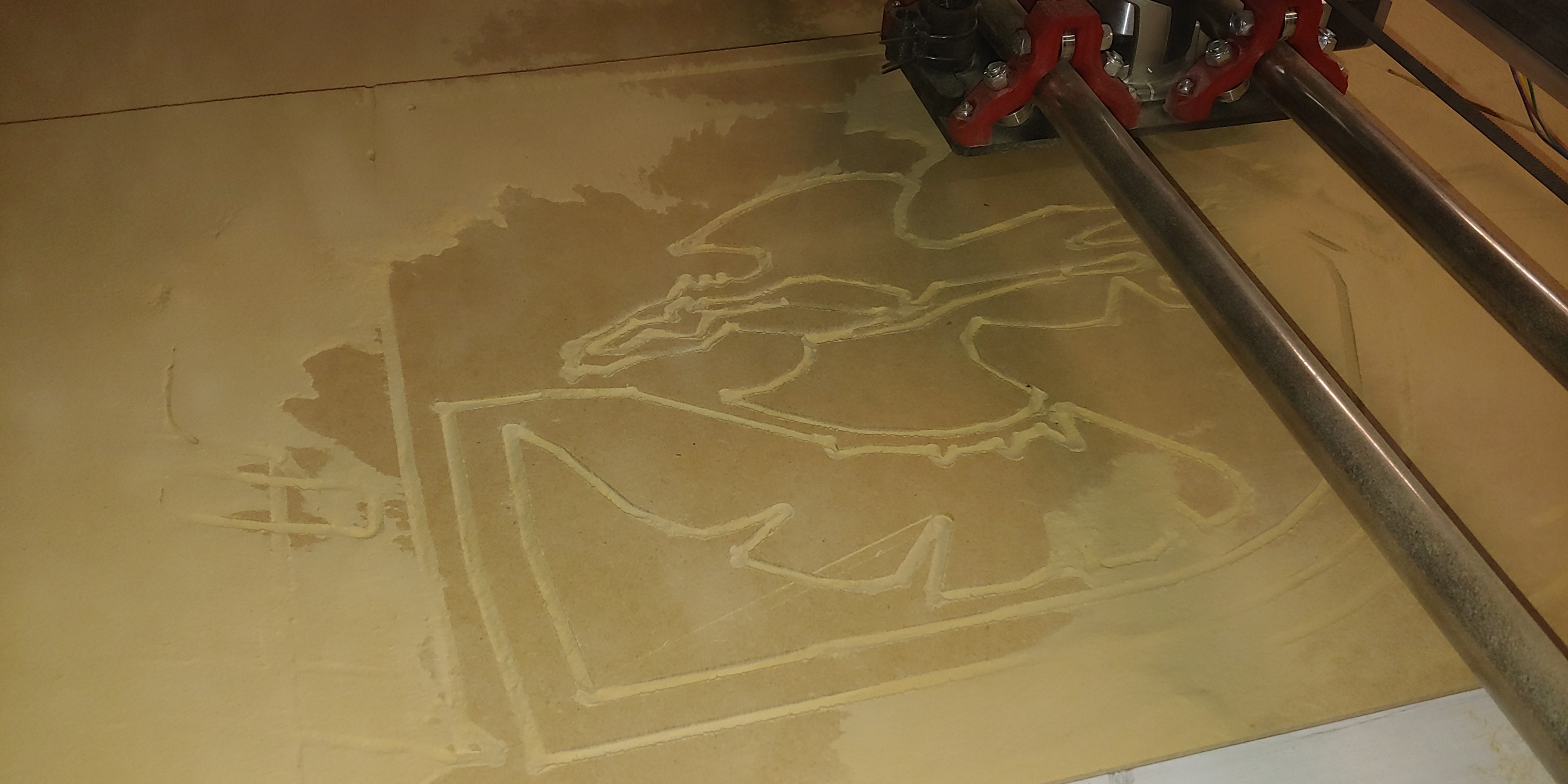
Making dust. I still need to work on wire management, but I wanted to get it spun up to test it out.
A couple of fits and starts while I tweaked the start height and gained an understanding of why the system wasn’t doing what I wanted, but we’re pretty solid now. The source vector didn’t like to be scaled up very well, but it turned out OK.
2 Likes
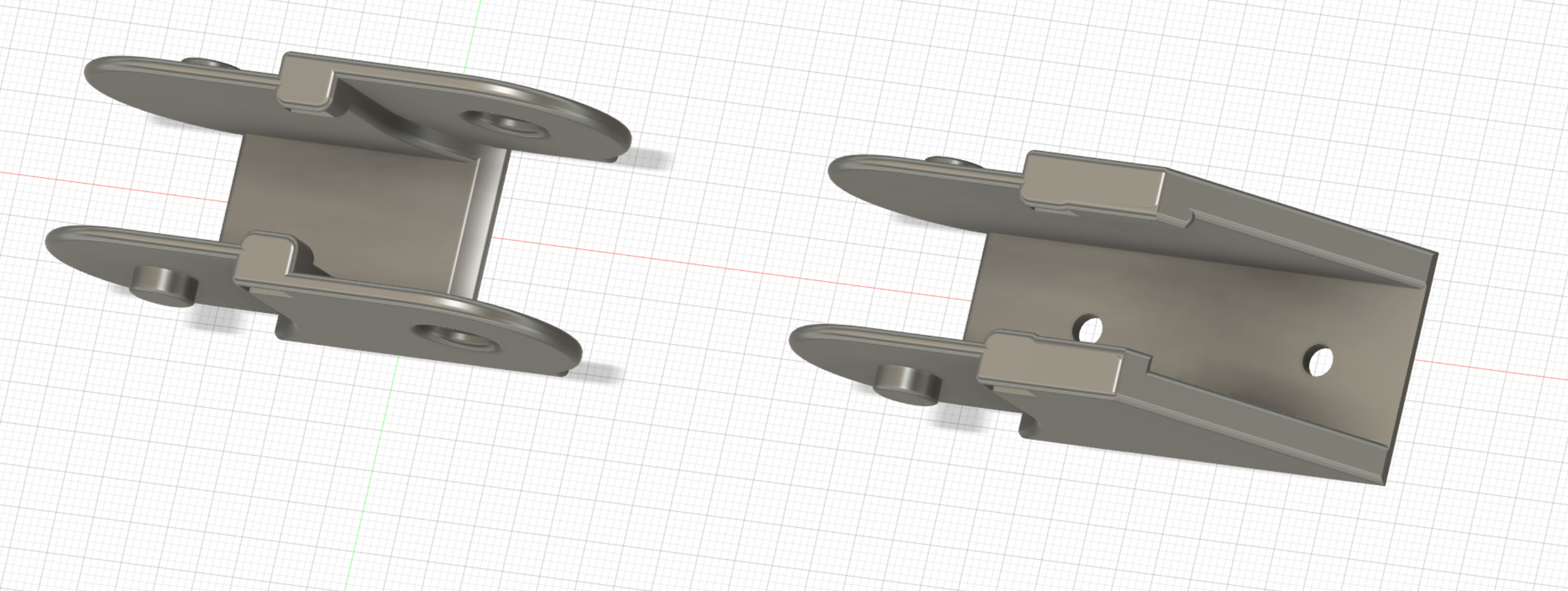
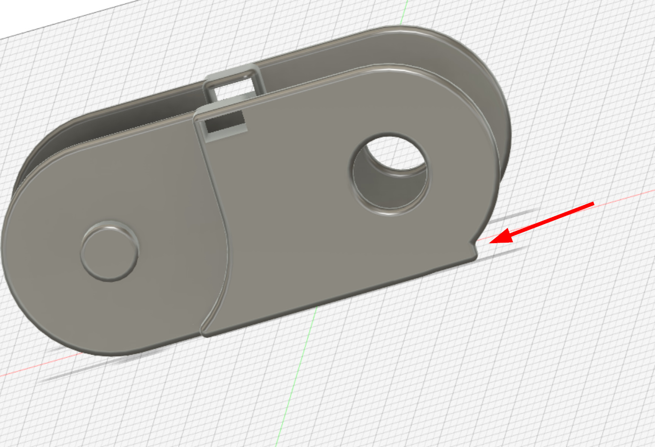
E-chain end-link design for use on the hose/wire channel and the Y-axis links. I need to design a stepper to E-chain link for the X-axis now, which I can do after I get the chain in place the way I want. I did revise the E-chain design a bit to ensure there was a rigid stop to prevent it from flexing in reverse. This should keep the chain rigid and minimize the need for support along the length of the Y-axis.
2 Likes
I have not attempted to design !inks from scratch but I have made dimensional changes to designs I found on Thingiverse. All 6 of the designs I have tried required a lot of support along an extended length.
@jeffeb3 I do print half of my links in one orientation and the rest at 180° from the first set. It makes the chain flow straighter.
1 Like
You’re right, it will still definitely need some support along the length. I used to moonlight at a machine shop many moons ago. Some of the links we had were able to self-support over lengths up to 6 or so feet, even with the weight of the wiring, air lines, etc. Igus makes some really great stuff for mobile cable control.
I don’t expect a printed part to support any serious weight over a large span, so I am still iterating some ideas.
So far, I have been fortunate. Of the 25 or so links that have printed, the chain does not appear to have a curve when assembled.
Here’s a shot of my x-axis cable chain.
Most of this was from thingiverse, except for the L bracket which has quite a standoff due to the limited radius of the chain. The drop between the chain ends ensures clearance.
2 Likes
My new chain design works beautifully and has an extremely tight bend radius in one direction with minimal arcing in the opposite direction. I expect it to hold up as well as as the one in your image Mark, but won’t know until I put it into use. I didn’t save the end bracket I made for the E-chain last night for some stupid reason, and Windows decided to install updates. So I get to redesign it again, which should be less than ten minutes of effort. I’m just pissed that I have to do it.
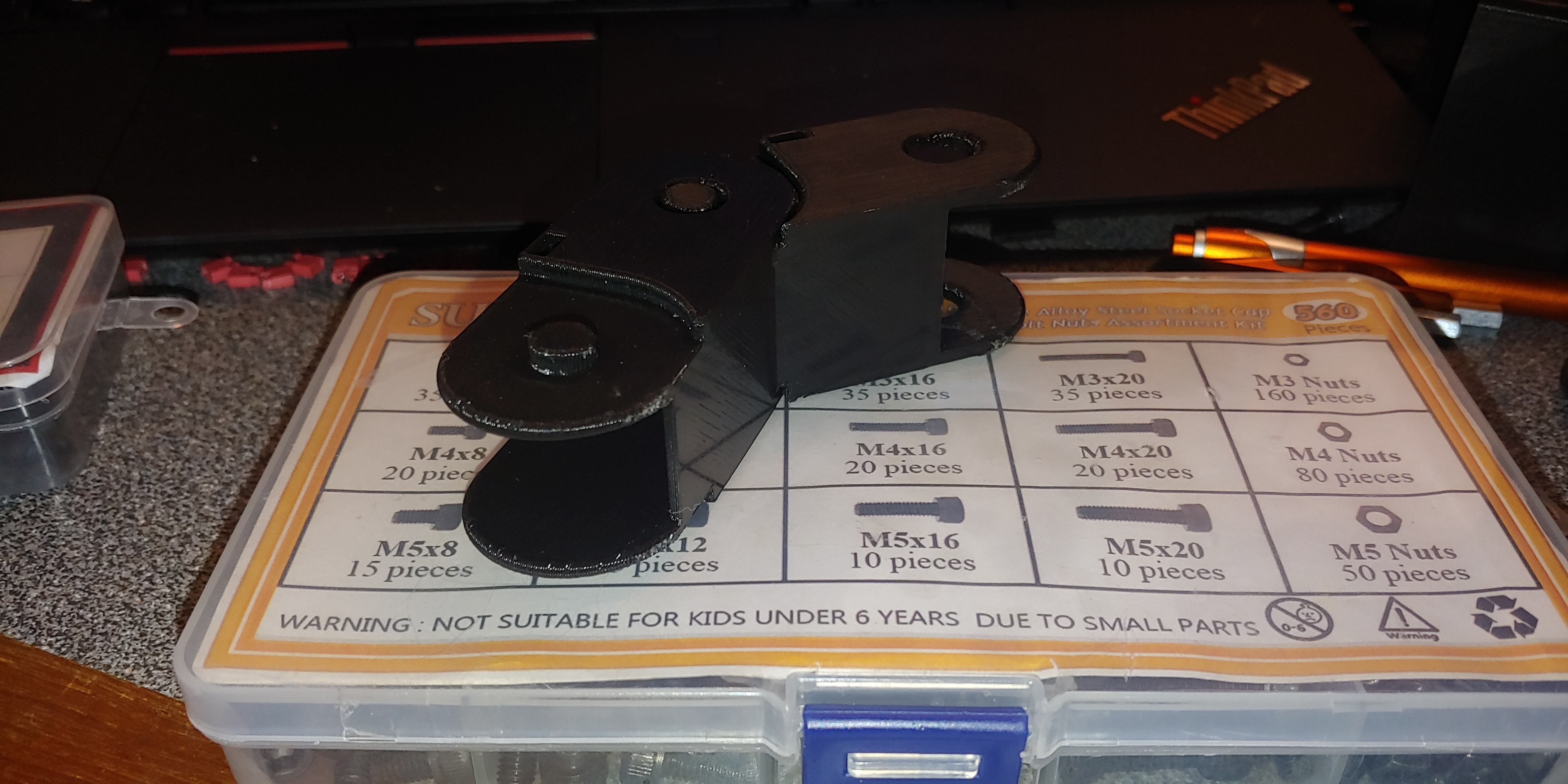
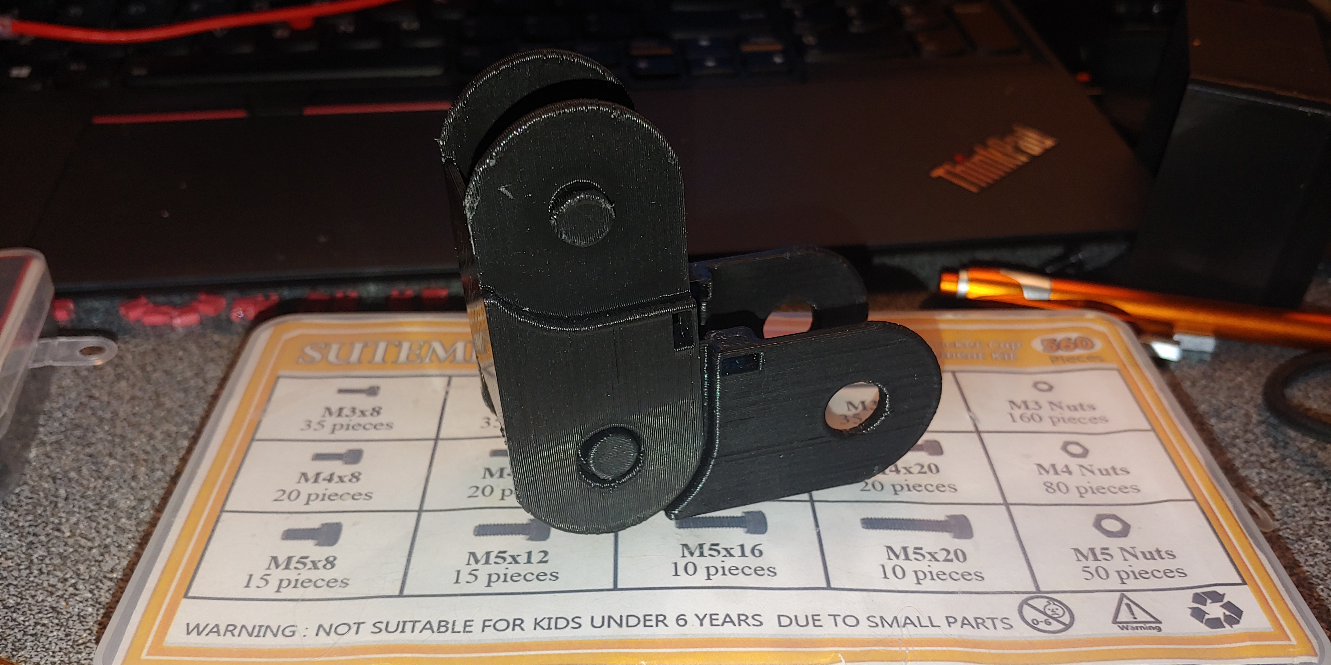
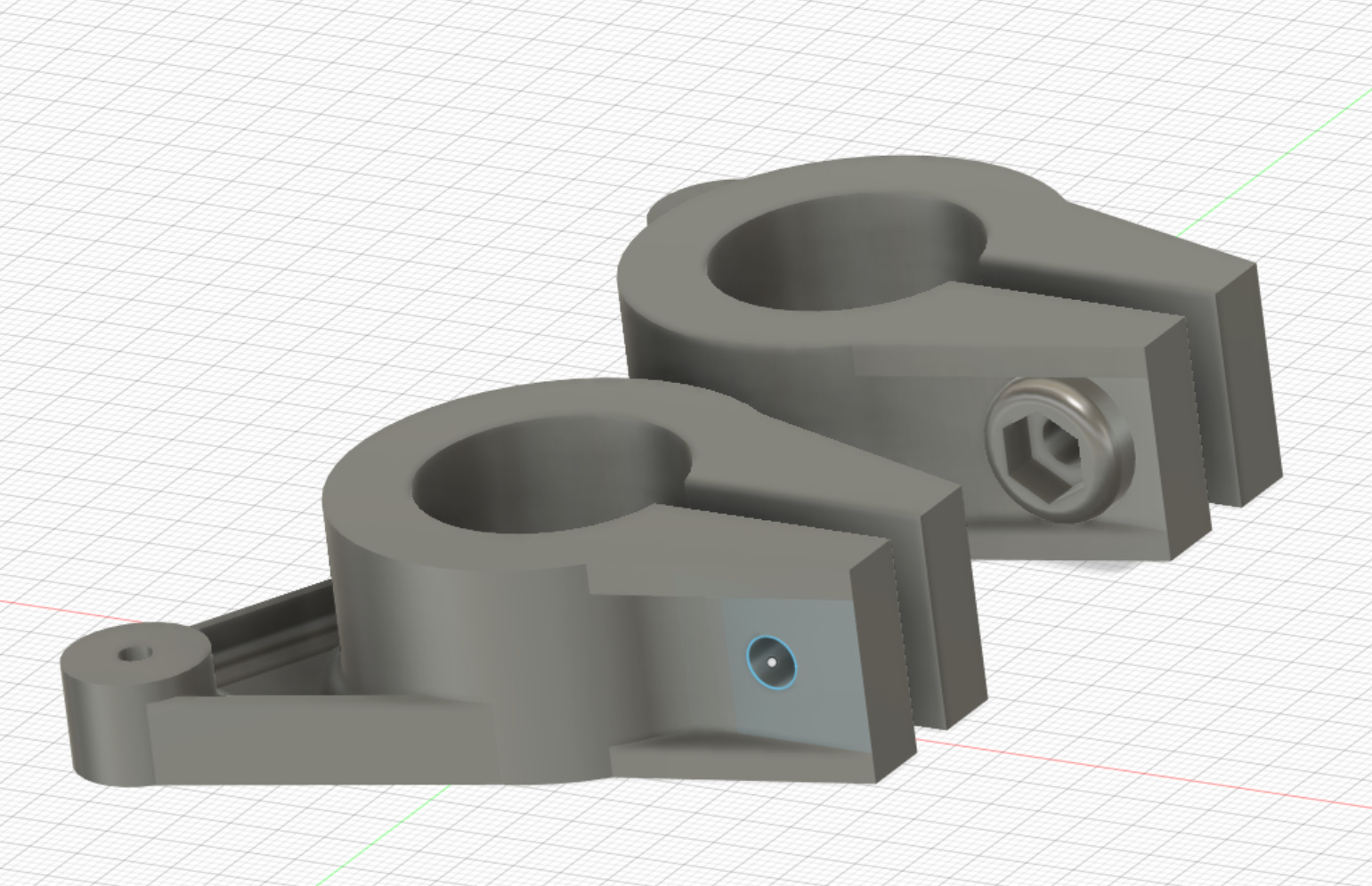
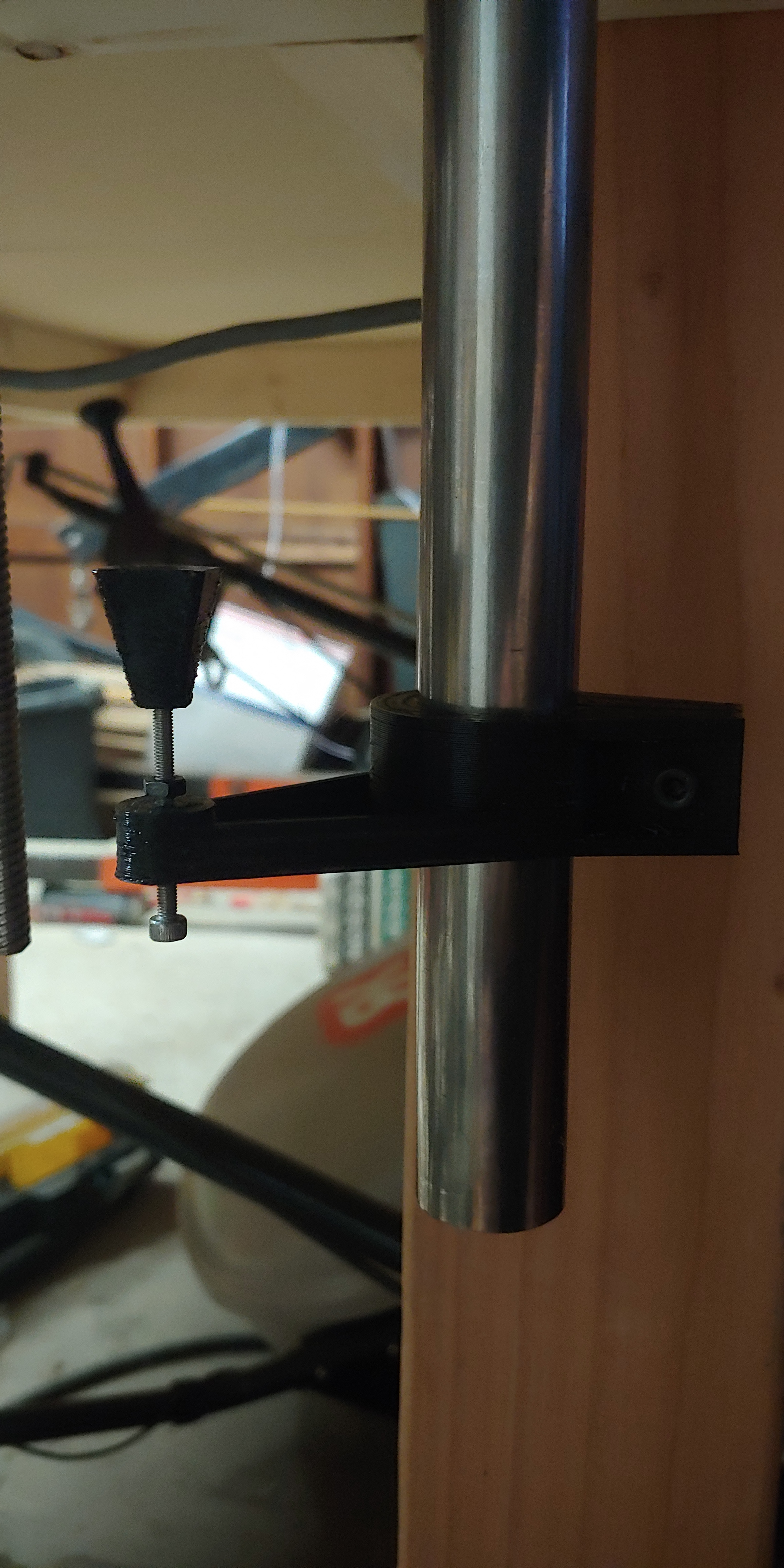
Tonight I modeled up the Z-end stops as well. These are modeled after a design I found on Thingiverse, but I can’t seem to find it again to give the maker credit. It is designed to fit around one of the Z pipes on either side of the gantry and clamp tight. The small extension off the side holds a M3x50mm screw very snugly with a small flat end cap on the end of the screw. The gantry rises, presses against the Z-axis limit switch which is mounted facing down, and stops. It is adjustable in large increments using the large M5 bolt to clamp around the Z pipe, and fine increments with the M3 screw. The limit switch will mount on a small printed plate on the outside of the Y-plate.
A buddy who owns a machine shop gifted me a bunch of stuff today to help with the wiring of my CNC.
He’s an old-school machinist, curmudgeonly, cynical, a bit on the asshole-ish side… And a great guy overall.
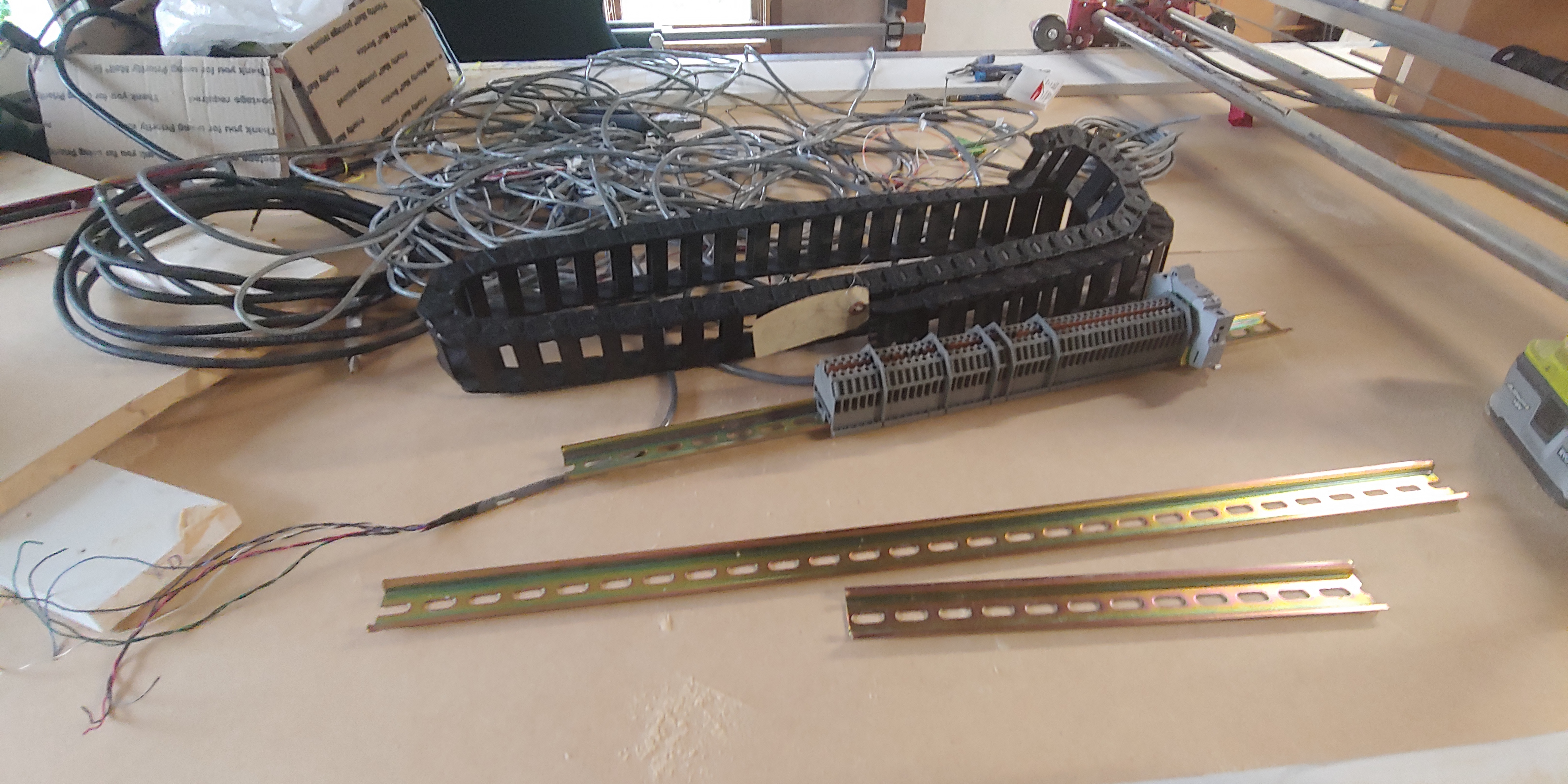
He tossed six feet or so of Igus E-chain at me for the Y-axis so I didn’t burn my printer down trying to print enough chain and then critiqued my homebrew E-chain (words of praise, from him, I’m shocked…), provided a bunch of DIN rail Dinkle terminal blocks and some DIN rails, and then a ton of machine wiring ranging from 2 conductor 14g for power to the spindle up to 14 conductor 22g for stepper/limit switch connections. He also included some extra tools and stuff for me. Additionally, he’s very interested in the project, and may build a CNC laser/plasma table using MPCNC methodology now that the DIY market has good quality consumer control boards.
Finally, he offered me some “upgrade” parts for mine if I ever wanted to mill inch thick plate steel… I told him I’d think about it.
3 Likes
Yeah, you should have no trouble driving those with the SKR… 
Are those the drivers on the left? 2U racks each!?
1 Like
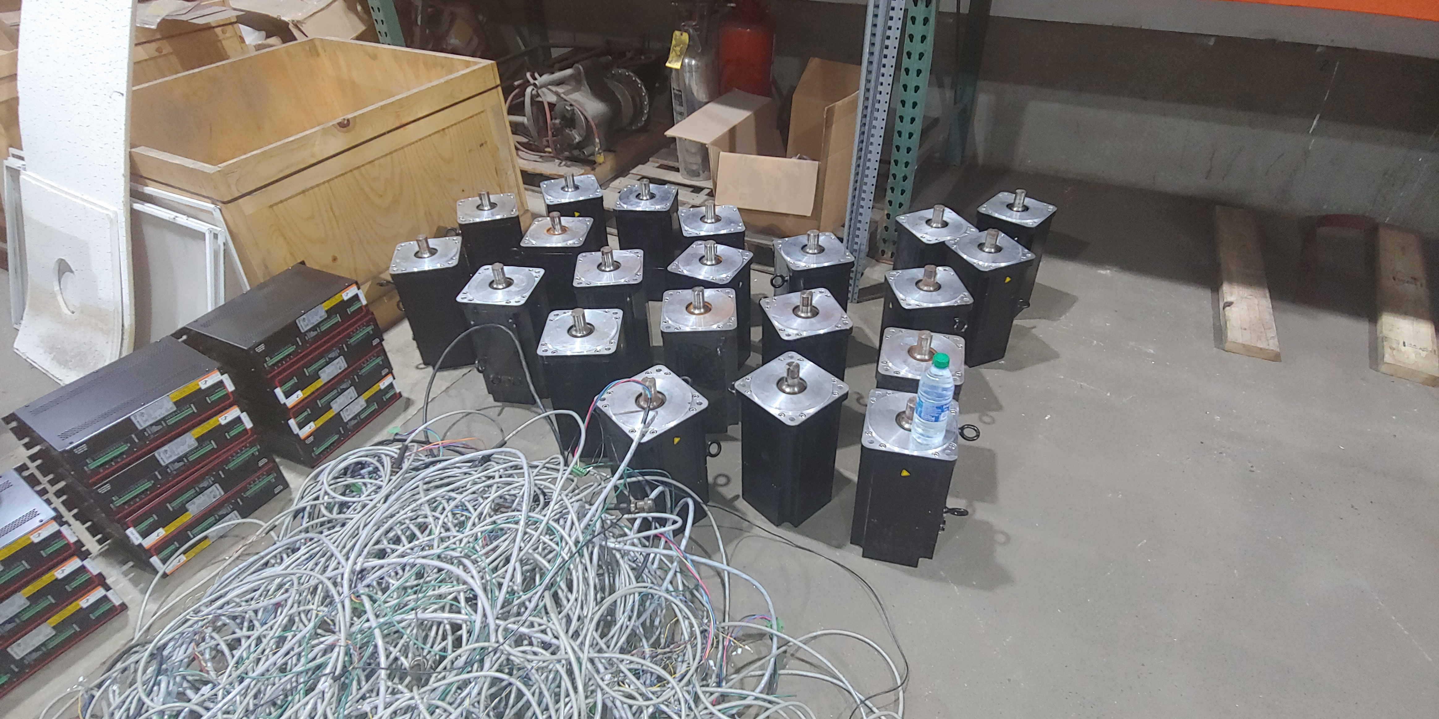
The drivers mount vertically in the cabinet they were pulled out of. These are actually servos with encoders. He says they need an analog signal to drive them. Each one weighs about 115 lbs.
He said each servo and driver combination would sell for over $5.5k on the used market, even without the cabling and connectors. You’re looking at almost 116,000 dollars worth of electric motor here.
 (long whistle) Man, cool gear.
The wiring has begun…
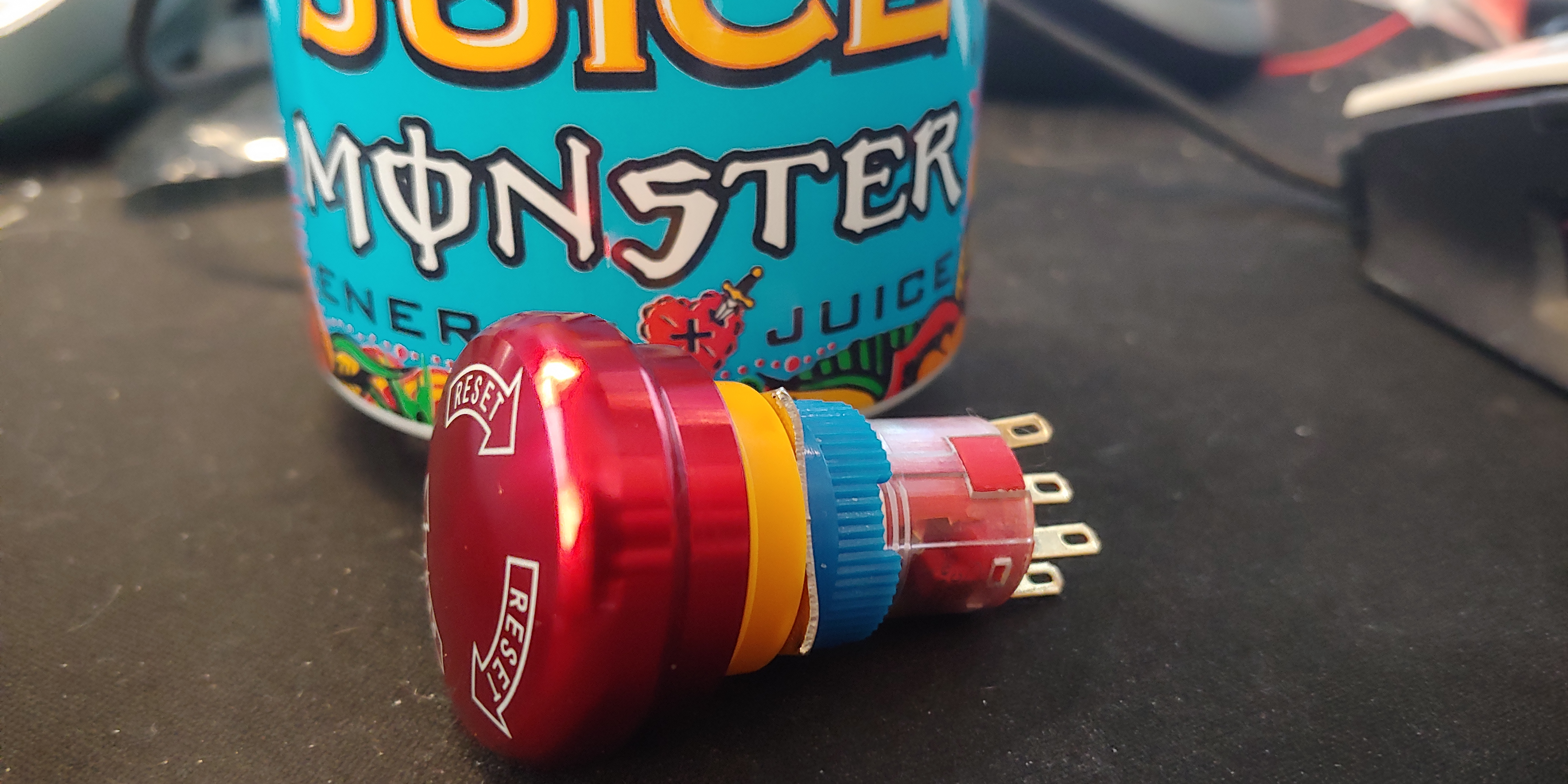
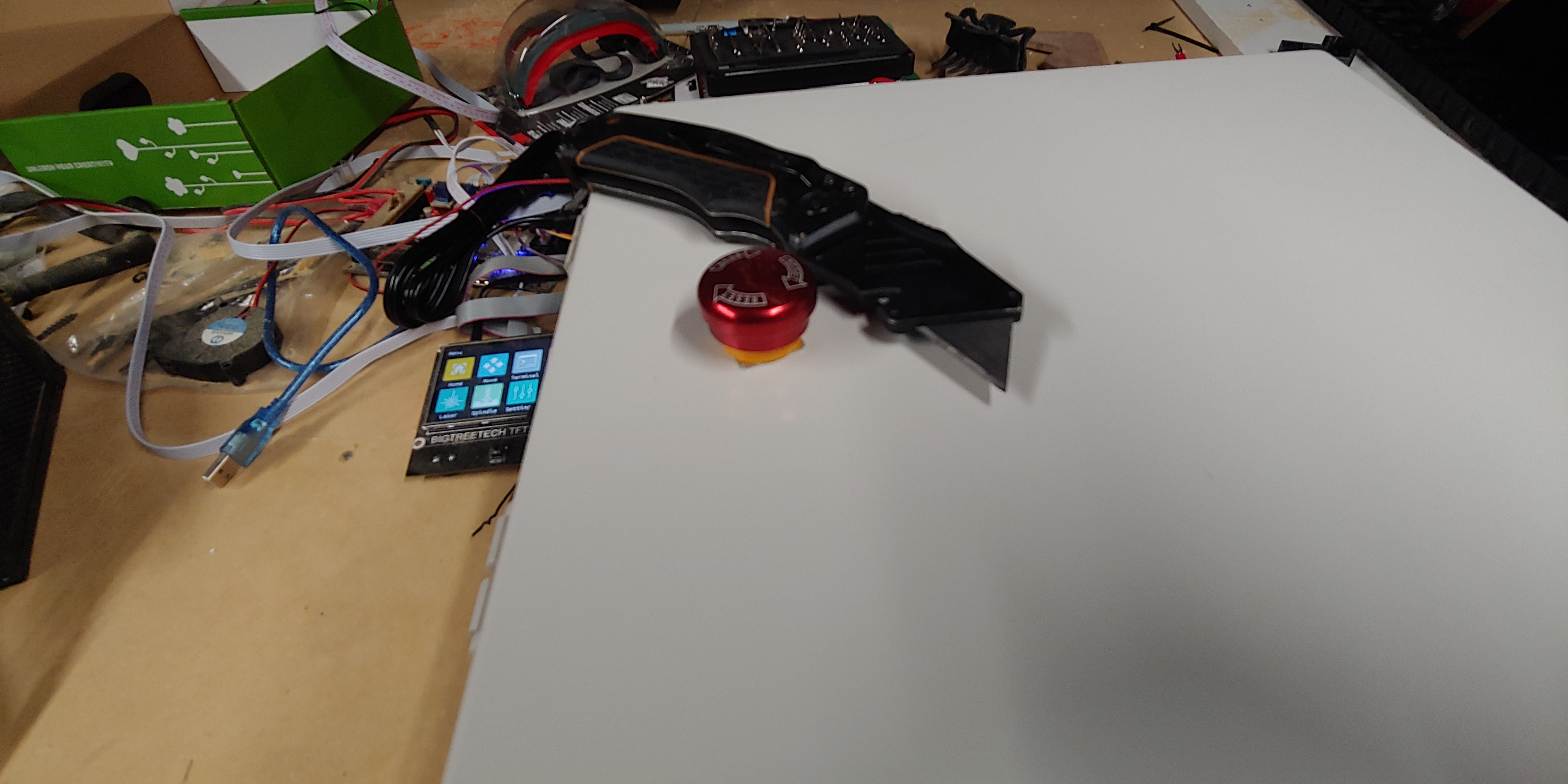
My Emergency Stop button came in… It was smaller than I expected. That will teach me to look at only the first picture in the listing and then check the contact specs before hitting Buy It Now.
Anyway, I printed off a huge batch of parts, and the only piece I have to print now is the X limit switch mount.
Speaking of the X-axis, my e-chain works beautifully, though my stepper to E-chain bracket is a tiny bit long, and I will need to shorten it by about an inch. The goal was to keep the E-chain from sagging over the back edge of the support rail, and it works beautifully for that, but at the far left point of travel, it torques the chain up over the front edge of the rail. It will be OK, but it’s not to my standards. Off to the Fusion 360 (again)!
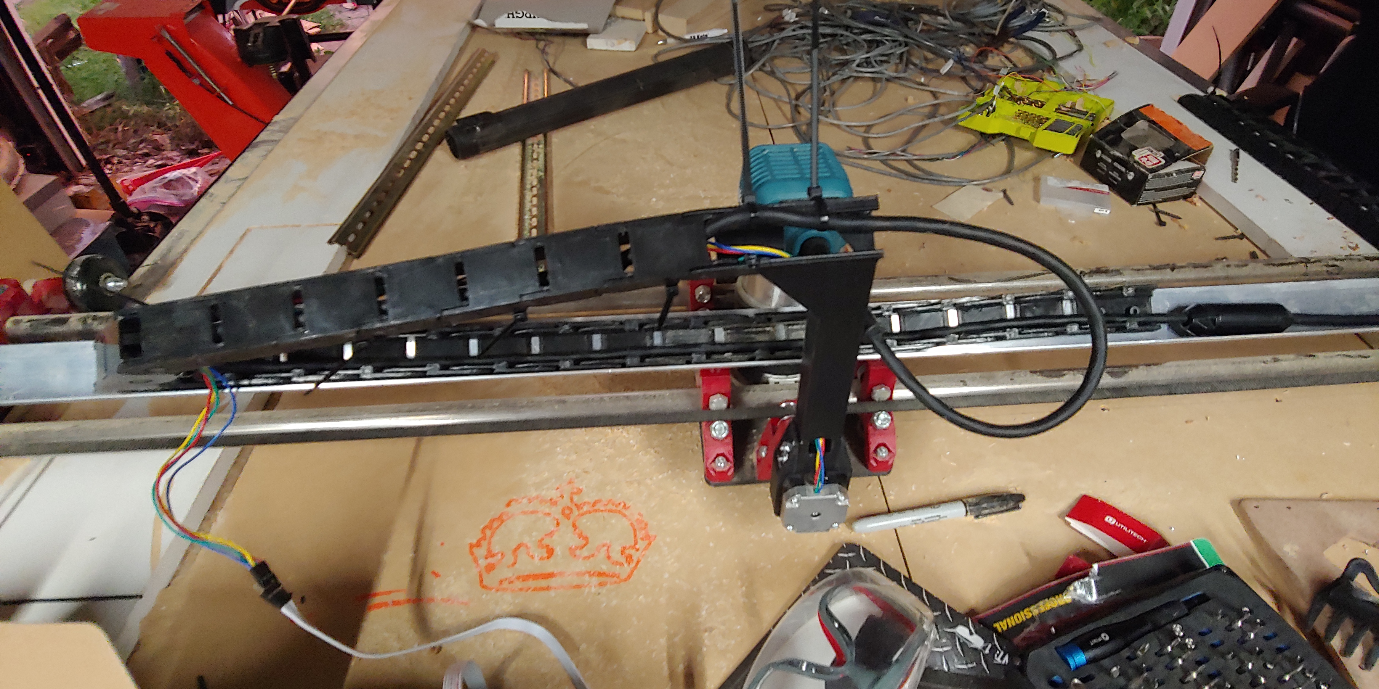
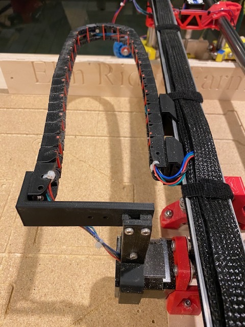
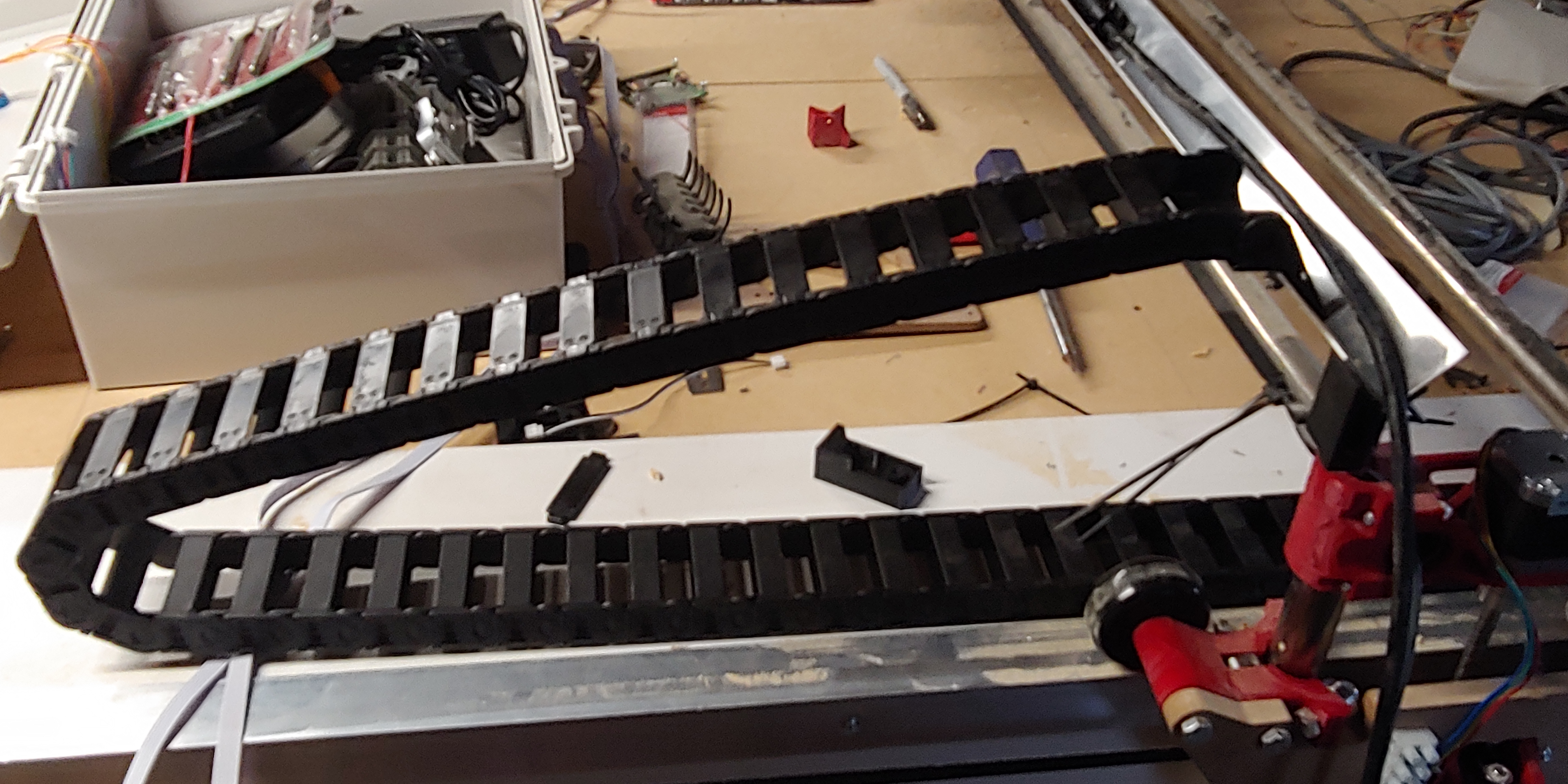
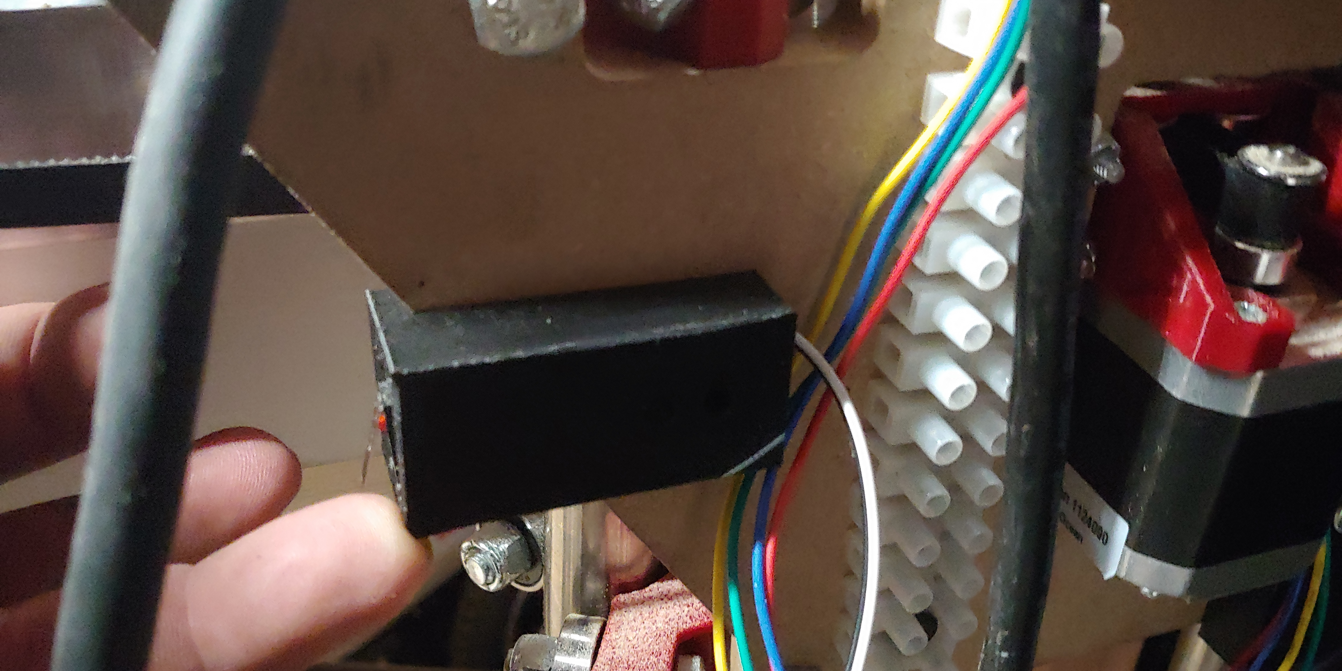
I found the perfect spot for my Y-axis E-chain. The table is wide enough that I can cut a full width sheet of MDF (49 inches) even with the E-chain taking up space on the right side of the table. This spot actually works quite well for me. I will be adding a limit block clamp around the X-axis gantry pipe to prevent the router bit from contacting the E-chain. Visible next to the chain is one of my Y-axis limit switches.
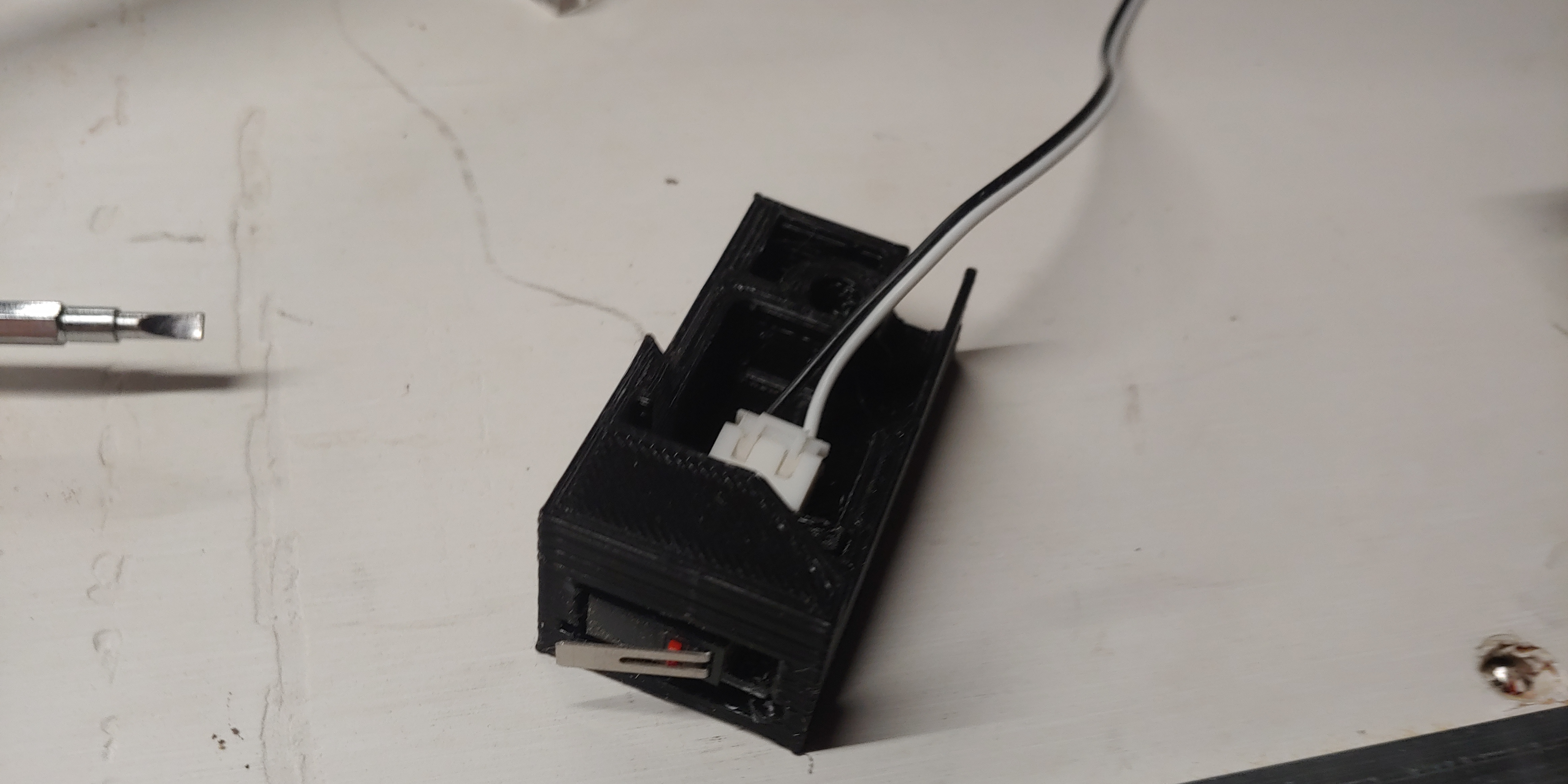
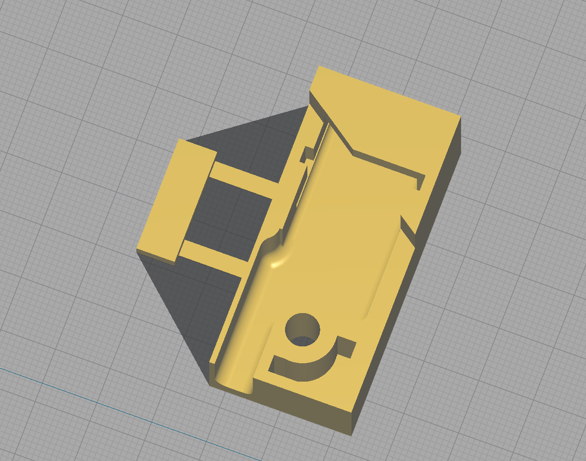
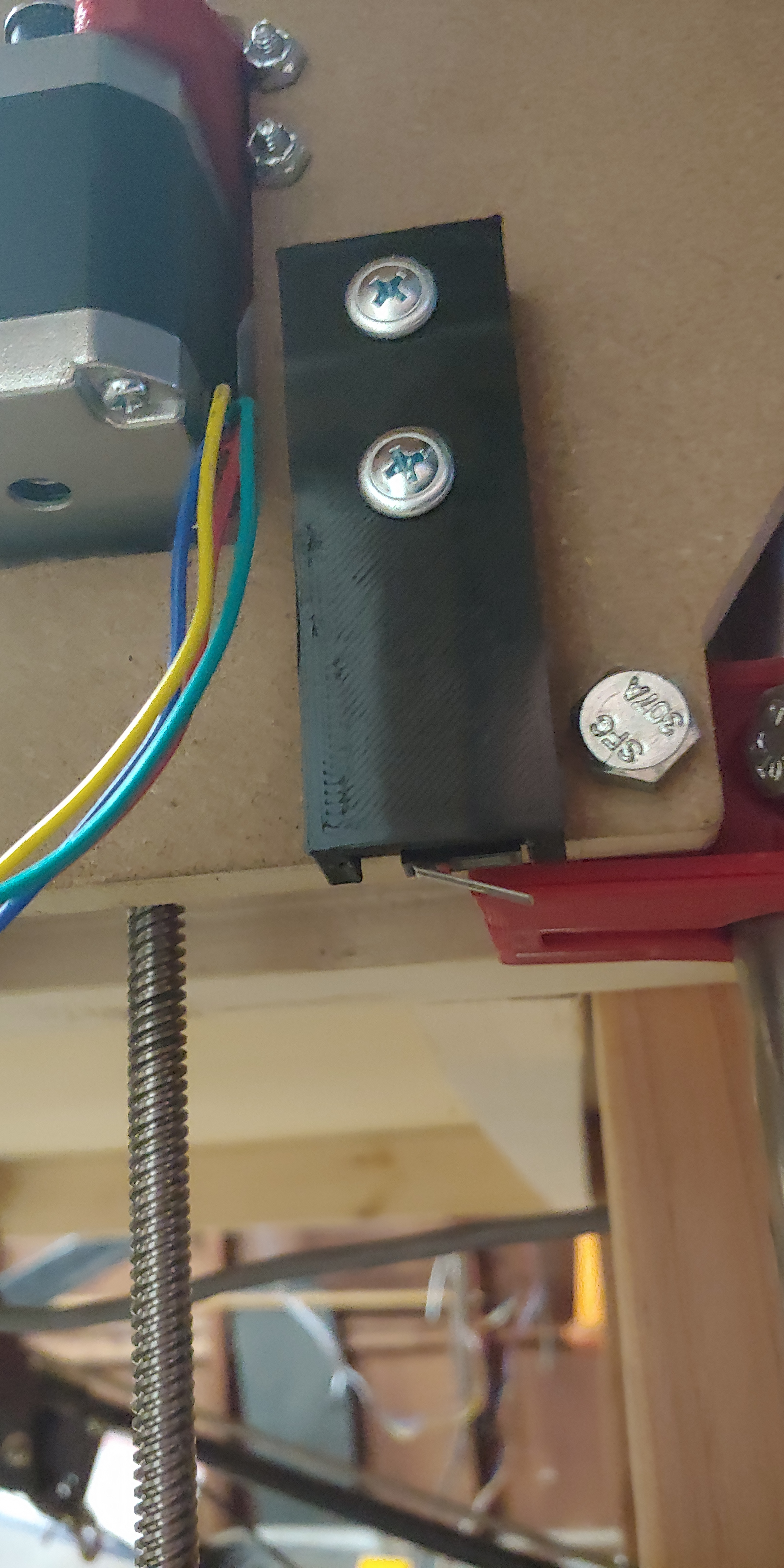
The limit switch slides into the slot in the front, and is retained by a small flat plate that inserts into a slot. The white connector bumps into this flat plate, and the limit switch can’t slide out. It’s very snug. The Y-axis switch mounts also have an angled surface that matches the Y-plate angle. Butt the switch up to this edge, align it vertically where your end-stop braces are located, and run a single screw in to hold it in place. Rock solid, easy to mount, easy to align.
The Z-axis does the same thing, only it uses two screws to hold it in place. Same exact locking method for the limit switch.
My Z-axis stops are triggered using a set of clamps that lock tightly on the Z-pipe. Fully adjustable with fine-tuning done by the screw and a jam nut to lock it all in place.
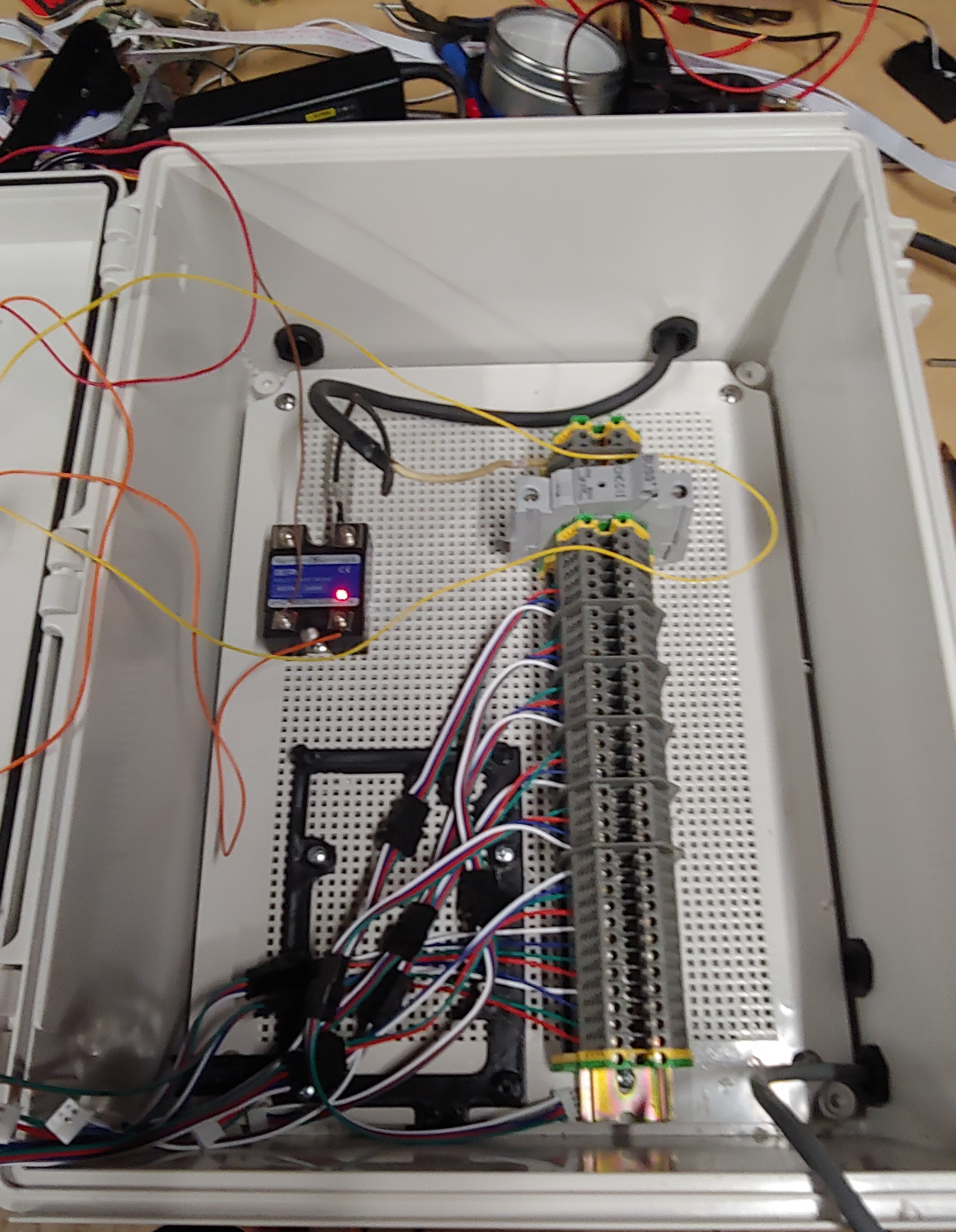
And finally, the enclosure I’ll be using. I got the Dinkle blocks mounted, added the ground terminals, the main breaker, and the solid state relay for the router. The black frame is the mount for the SKR Pro, and I created jumper cables using a combination of the white locking connectors and some locking JST connectors. I made several extra sets to have as spares, and I can disconnect the JSTs in order to plug in steppers at the box to test in the event of a stepper issue on the machine. It leaves a bit of a mess for the wiring, but that’s OK. I have the blocks wired from top to bottom in order of axis connector on the board, and the bottom sets of blocks are for the limit switches.
One more of Baby E-stop.
1 Like
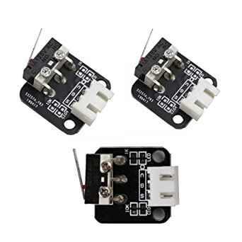
Love the limit switch holders. Care to share?
I’m more than happy to, but have to state that these are meant specifically for the Ender 3 limit switches though they can be modified of course. My step files are embarrassing, as I am still brute-forcing my way through learning Fusion 360 and haven’t figured out how to do things with style and panache. Let me get everything exported and I’ll get them attached in here some time today. I’m also still working on the adjustable end-stops for the Y-axis. They could be more compact, but that’s the nature of my particular machine.
1 Like