I need to try and get seafile working on my octoprint/cncjs systems.
sftp is a very solid protocol, but to each their own. If you can ssh into a machine, you can use scp or sftp and it respects the system’s permissions. There aren’t any special variants. If you need an http interface, then yeah, there are lots of choices. But, BTW, octoprint already performs the function of an http file server, but it only has access to it’s upload folder. If that was just the same as the cncjs folder…
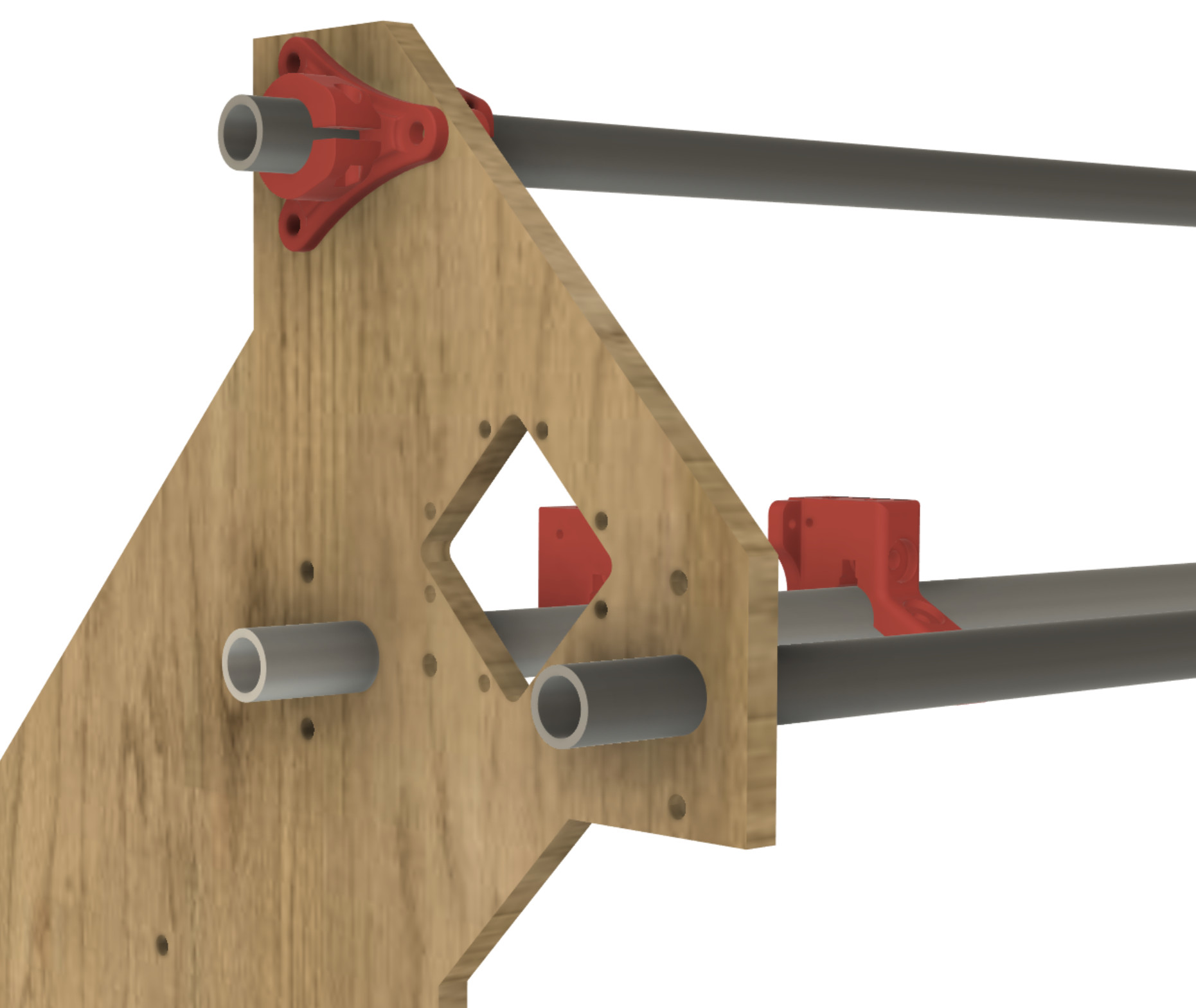
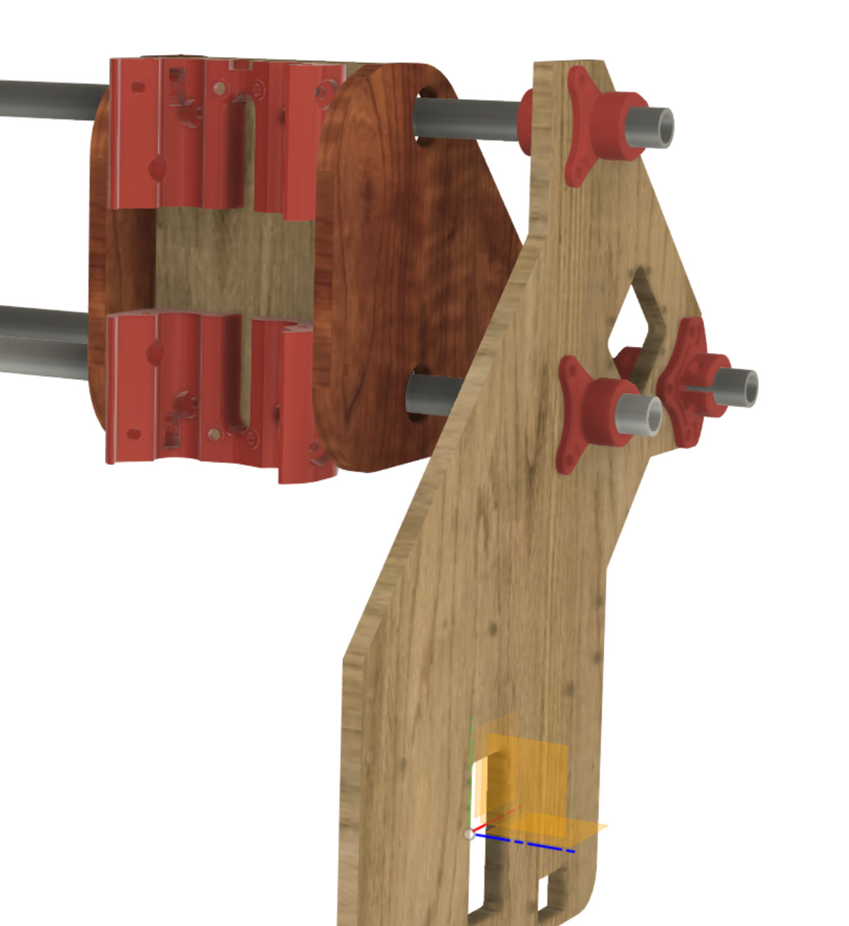
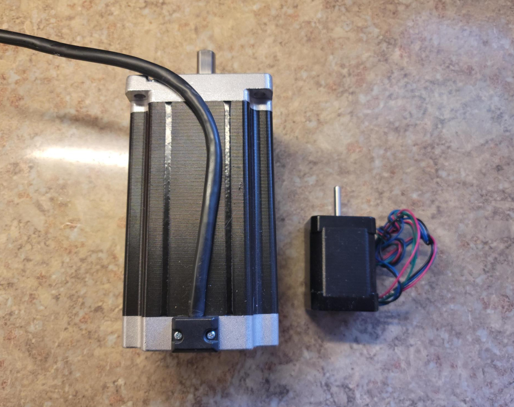
I am working on a Primo/LR2 hybrid machine with a fixed height gantry, mocking it up in Fusion 360 for fun/ideas… This design would use modified Y plates that could accommodate 92oz-in NEMA 17 Steppers or handle larger NEMA 23 if so inclined. The Y plates would be milled from 12mm Baltic Birch, two layers per side for rigidity, and would include mounting holes for roller wheels to ride on the top of the table as well as adjusters for lower wheels to run against the bottom of a track to keep the machine firmly affixed to the table. In my case, I have 16mm supported linear rails for my Y axis, so I included some holes spaced higher to allow mounting to 2 inch aluminum angle bolted to the bearing blocks. The screenshot below does not show some recent changes I have made to the plate to include the lower adjusters, etc, nor does it show the full thickness.
As you can see by the plate design, it will be a three pipe gantry using some slightly redesigned bearing carriers (visible on the front lower pipe) which will allow a wooden X plate to be vertically mounted on the two vertically stacked pipe bearing carriers, with a bottom plate attached to the bottom of the front bearing carriers and to the back bearing carriers on the rear pipe. This should increase stiffness considerably, and the vertical and bottom plates will be buttressed with side wooden plates.
Where does the “hybrid” come in, you ask?
Modified Primo leg locks (top of each leg, under the X/Y attachment points) will go on the X pipes, one inside the Y plate, one outside. Pushed against the Y plate and tightened down, this will lock the side plates to a fixed position on the pipes on either side. Concern about the Y plates being able to lean left/right into the X axis can be alleviated by an alternative design I am mocking up that includes a larger flat surface that can be bolted through the side plates. I’ll get those mocked up and post photos when I can.
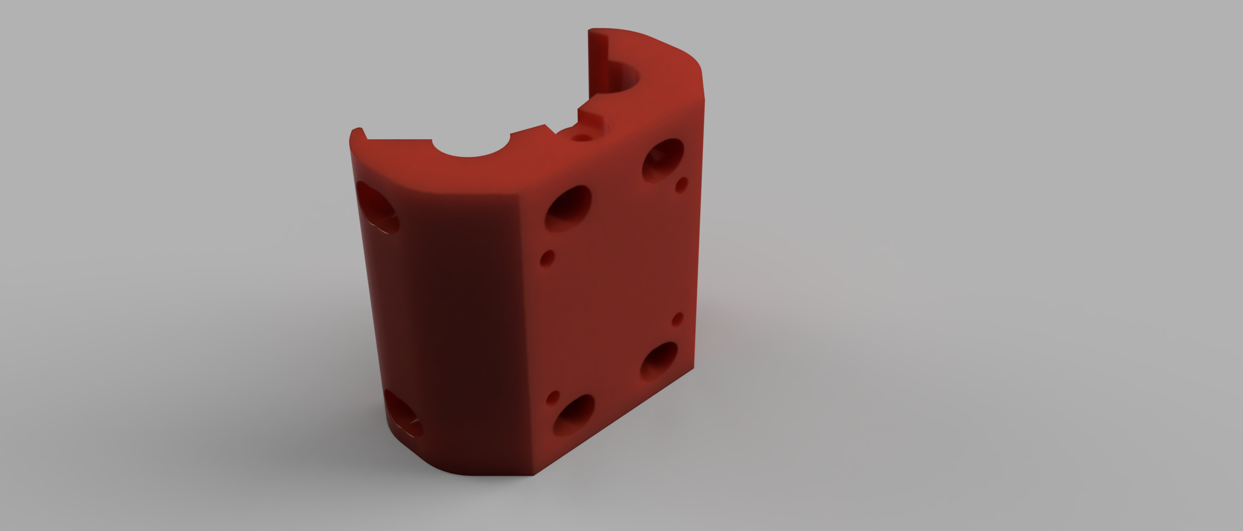
The other part of the Primo hybrid piece, and I have asked for some assistance with it, is to use a modified Primo Core. The flat logo’d face of this would be bolted against the vertical portion of the X plate and use the same exact pipe/bearing mechanism for the Z motion. Without the need for bearing holes/mounts for X/Y pipes, those spaced could be repurposed to bolt directly through the flat surface of the X plate.
I’ll continue mocking things up and post photos as I go…
Unrelated to above:
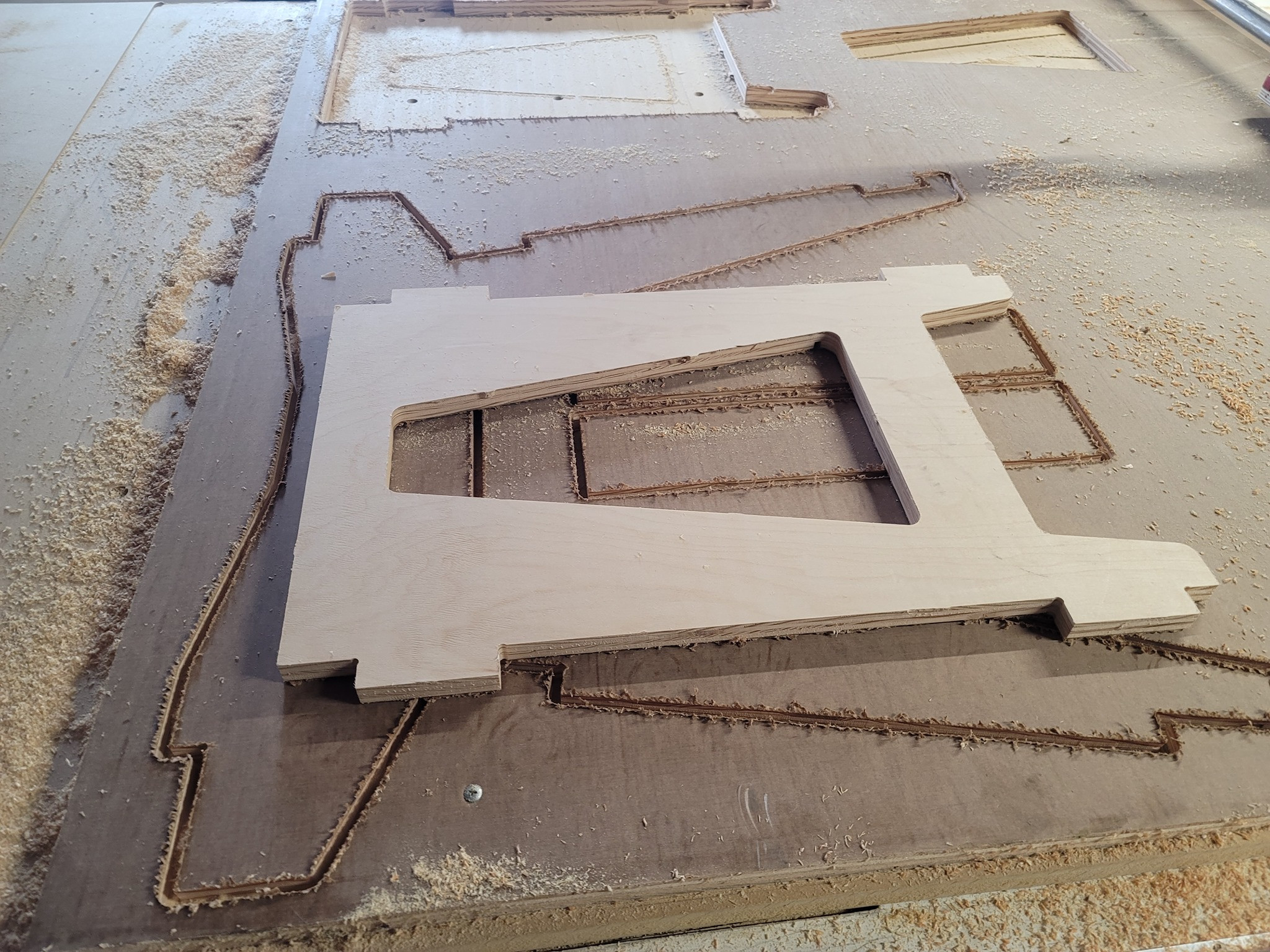
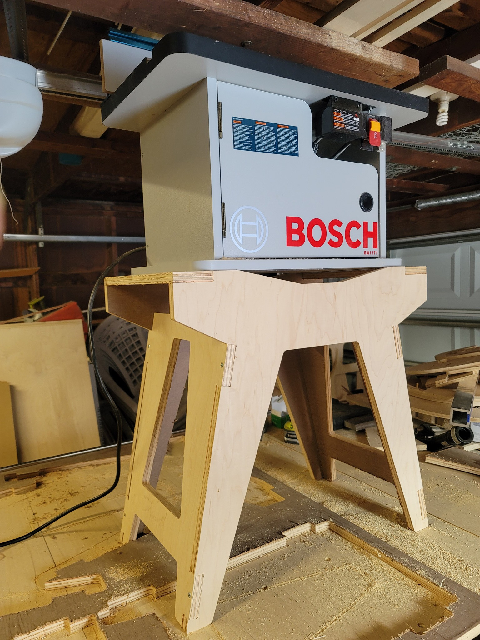
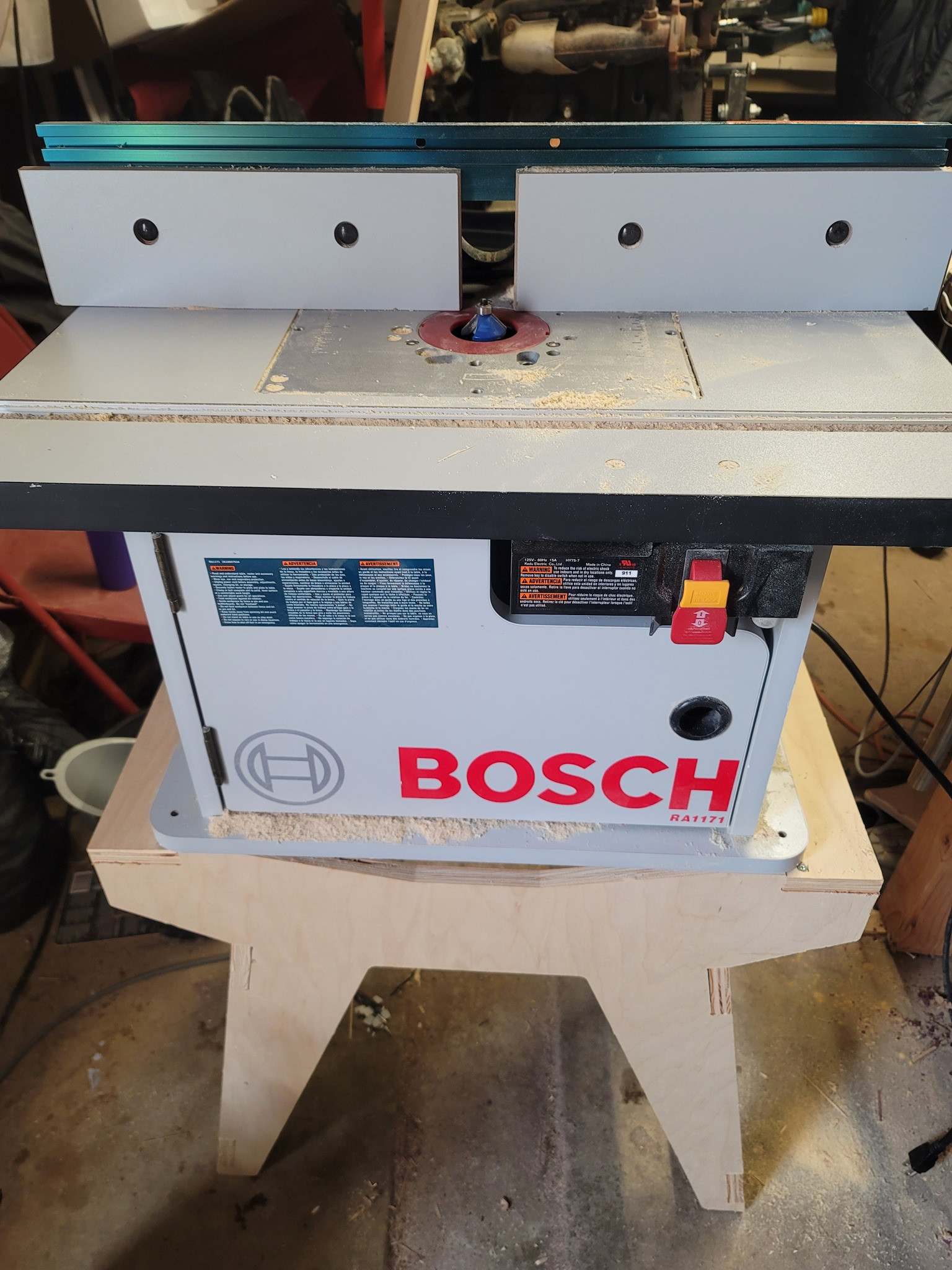
My bench top router table sits too high for practical use when placed on the only work surface in the shop, the CNC table… So I designed a router table stand. I guess you could say I’m a tool using one tool to build parts for another tool… Toolception!
9 Likes
That toolception looks great.
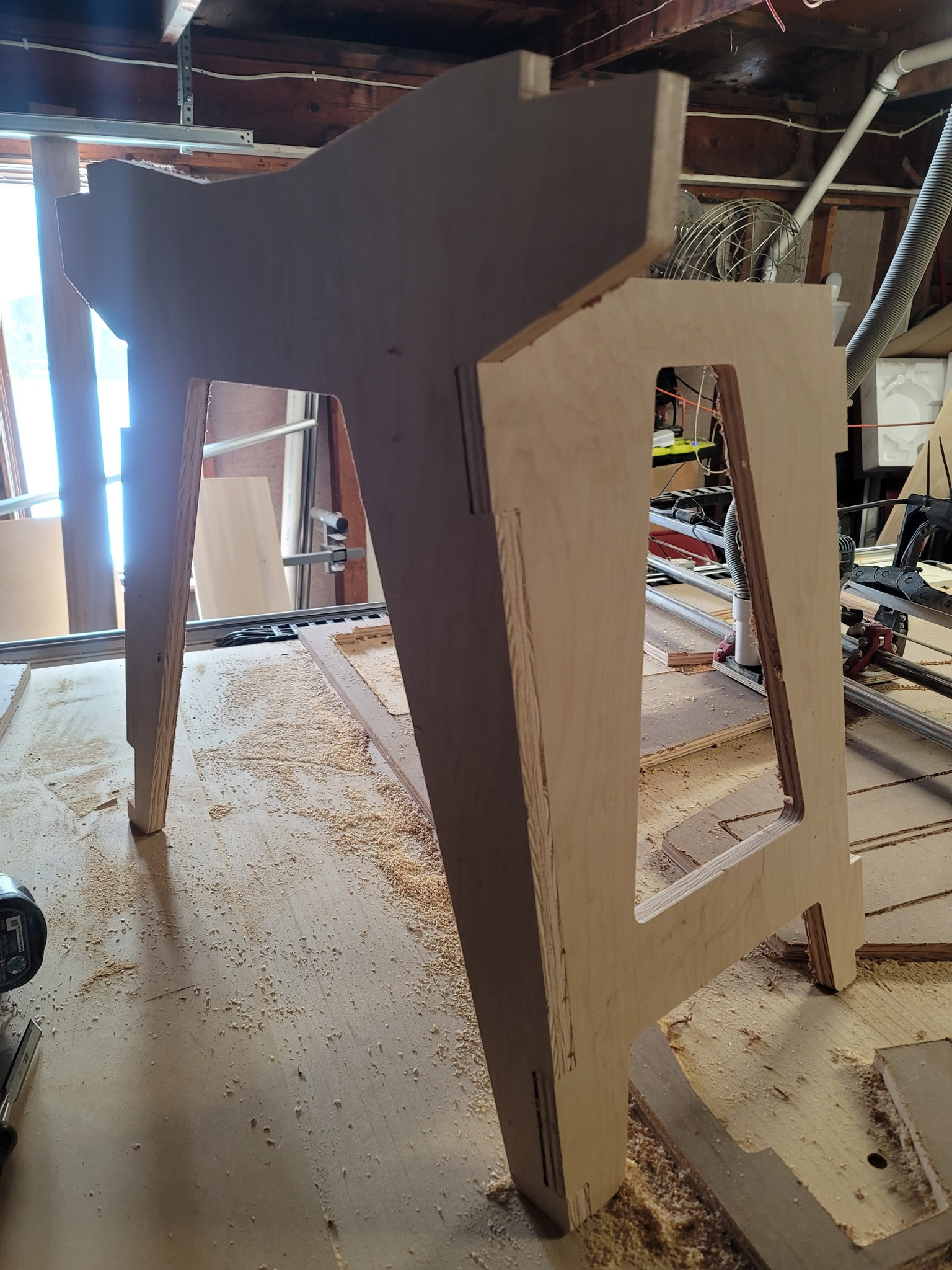
Thanks! It’s strong enough to hold my full body weight, and pretty stable as well. I have a mini drawer storage rack that I can attach to the side of it on the slight angle to hold all of the bits, etc.
I’d be looking for other stuff to make stands like that for too. Standing desk? Raise the mini fridge? Drill Press?
It’s not as refined as the Primo core, but the dimensions are identical, except that the top/bottom bearings are further apart by a little bit. Four bolts (the four deep pockets) hold it to the X plate.
1 Like
Still working on the design process for the fixed-gantry LR2/Primo hybrid. Whether or not the machine comes to fruition, I’m enjoying the design process and the problem solving that I need to do…
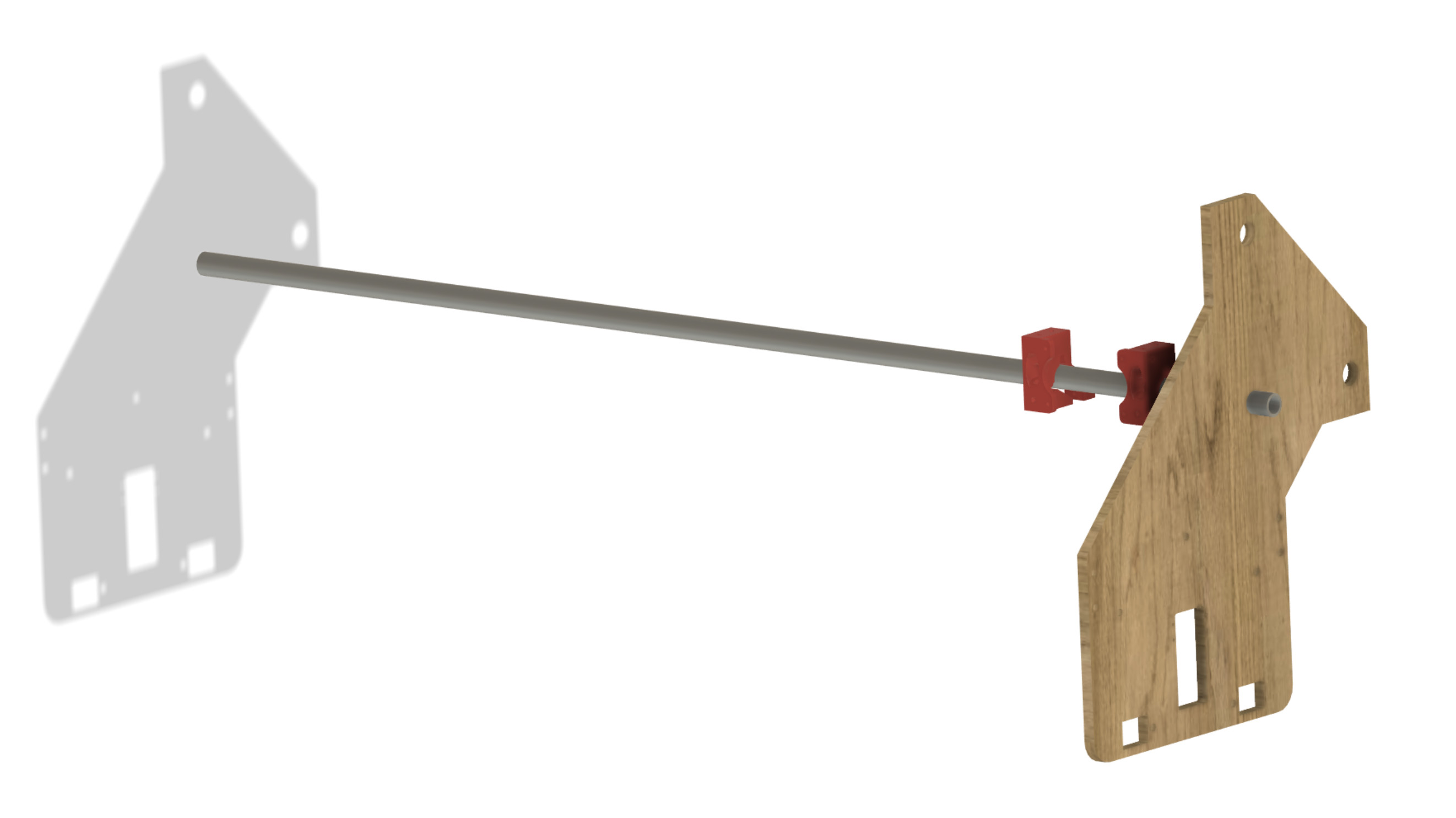
One of the things I’ve been thinking about is how to fix the pipes that pass through the new Y-plates to the Y-plates in a manner that makes them super rigid. I think I’ve come up with a design that will provide very good support for the side plate to pipe connection, and will be an easily printable and repeatable part.
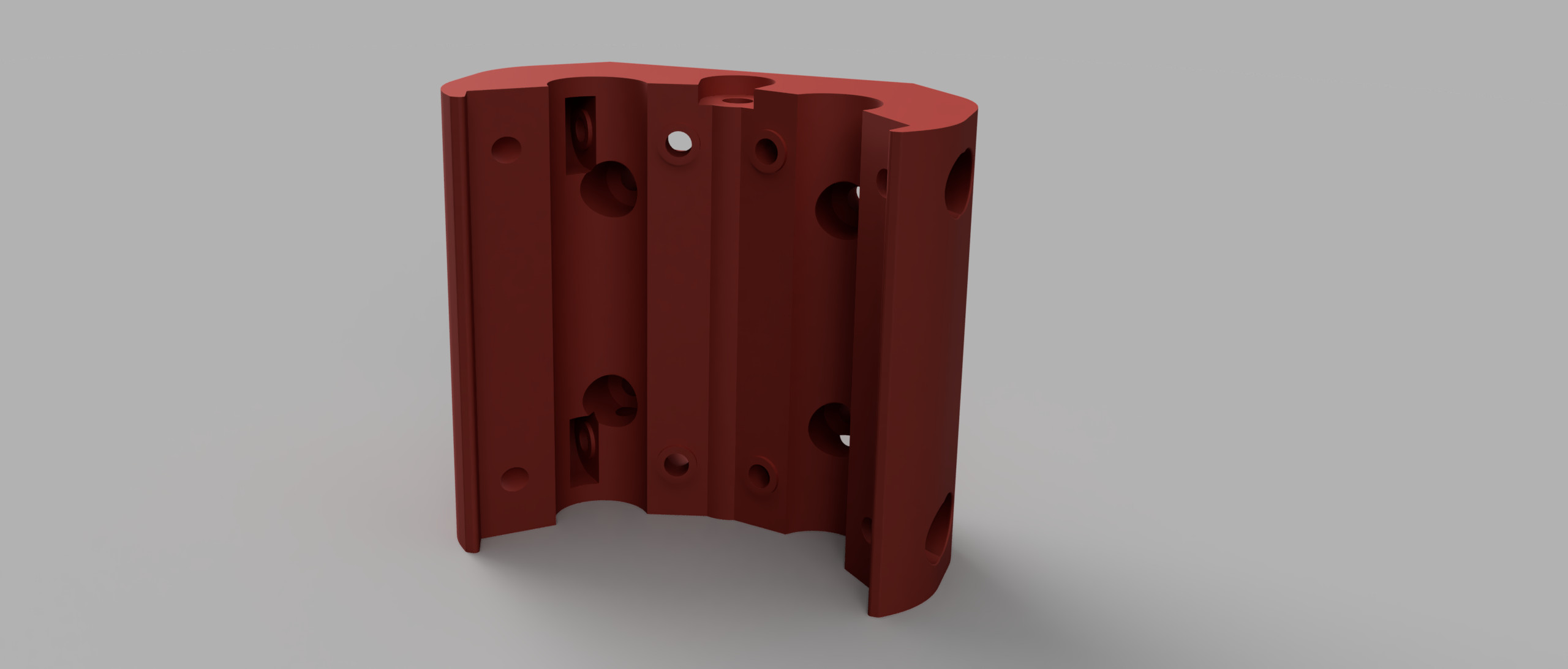
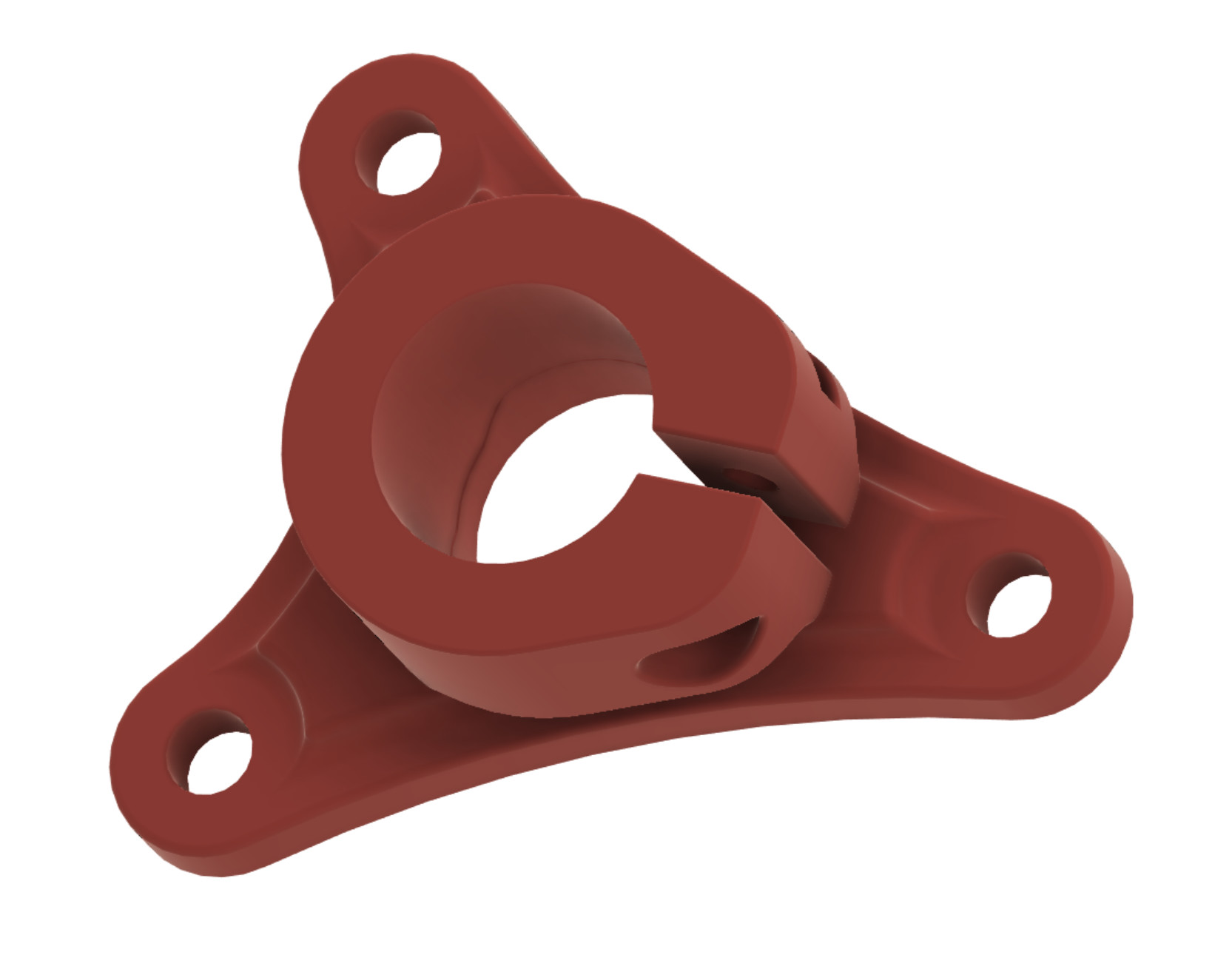
This is a pipe clamp. The two small holes and the tab at the back are attachment and alignment pieces, respectively.
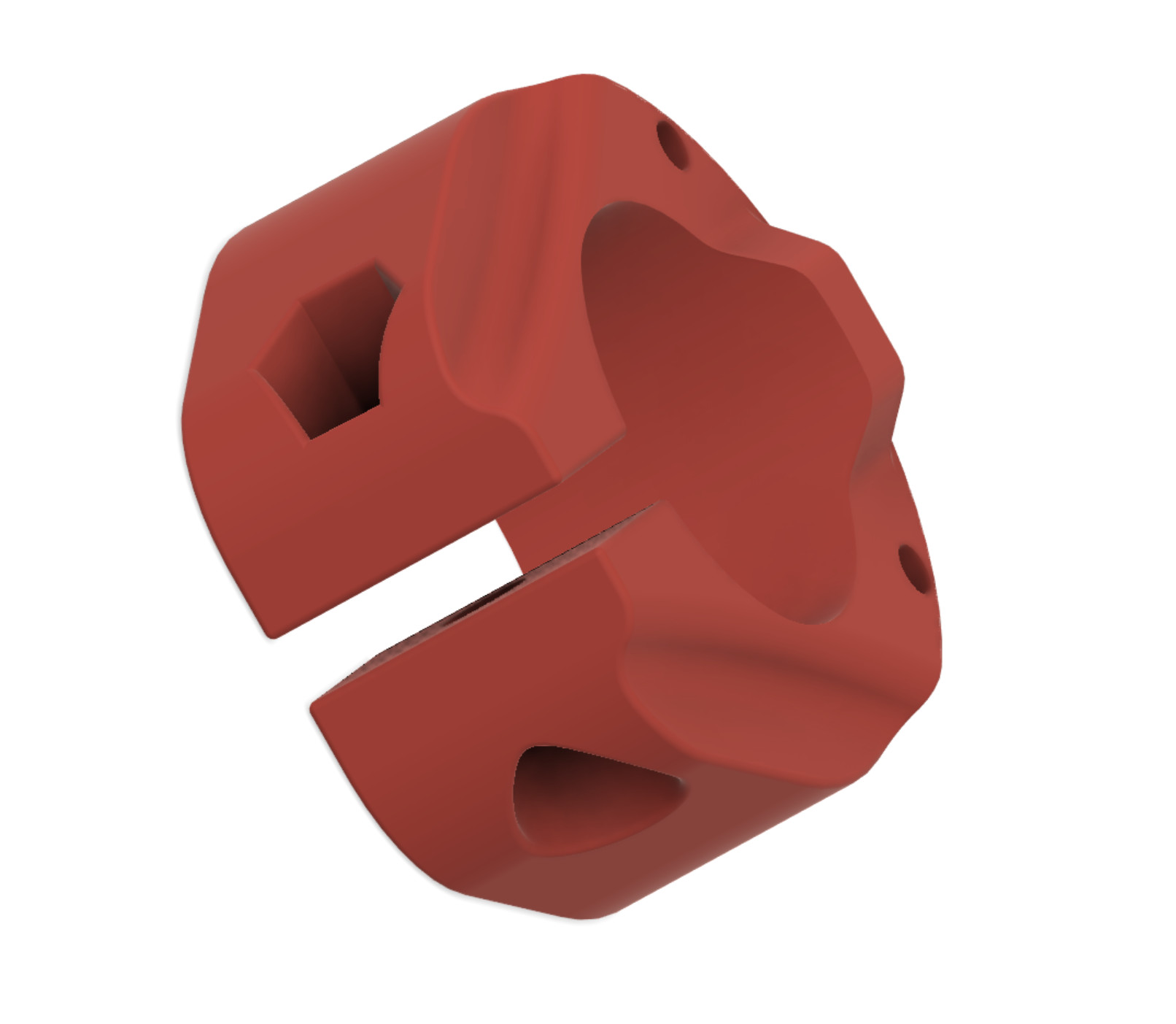
The alignment tab that sticks out would slot into a matching receiver slot on the mounting plate. The two holes are designed for M3 screws that screw in from the backside of the plate. I have created a spot for a third screw on one side of the clamp ears, but did not model it up for this shot. This will fix the clamp in a known position against the mounting plate. The three holes through the mounting plate are for 5/16" bolts to pass through a matching plate/clamp on the opposite side of the Y-plate.
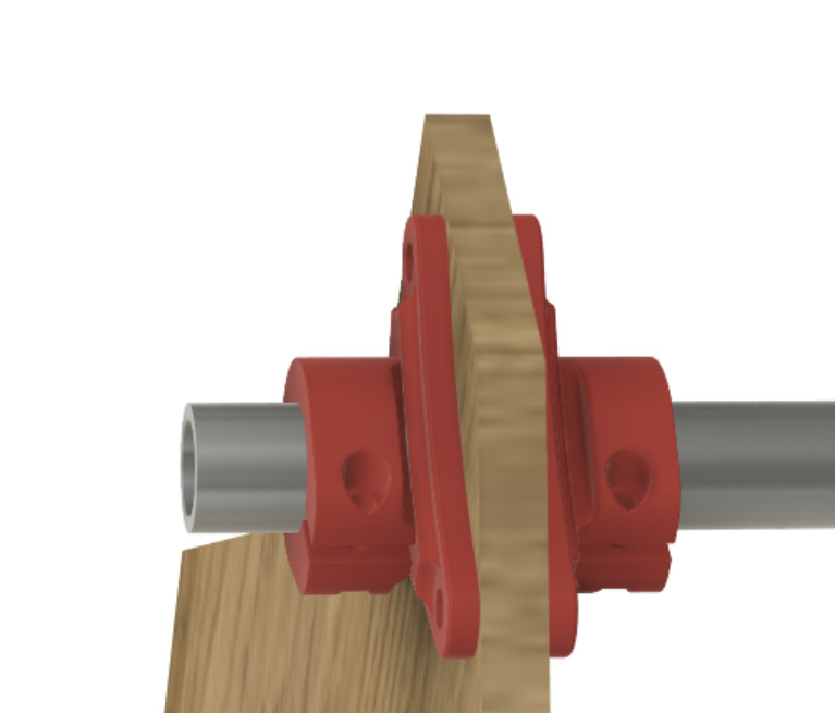
There will be a set of these at each pipe location in the Y-plate. Overkill? Maybe. I thought about making them a single cohesive unit for each clamp, and I have a mockup of that that looks identical to this two piece unit, with a small channel between one ear of the clamp and the plate so the ear can flex. The hole in the Y-plate for the pipe will be the diameter of the pipe, so it will already be a snug fit, and the wood will be the piece that actually holds the pipe in place on the Z/Y axis, while these hold it on the X axis.
I have also added some features to the Y-plate that will make the machine modular… The large square opening is sized to fit a NEMA 23 or smaller stepper with a 3D printed adapter plate. Print the plate you want for the size of the stepper you have and use a ball screw, or print a plate that offers a belt clamp and tensioner if going with a X-plate mounted stepper like the original LR2. The plate inserts into the opening in the Y-plate, and attaches using 8 M6 screws around the perimeter.
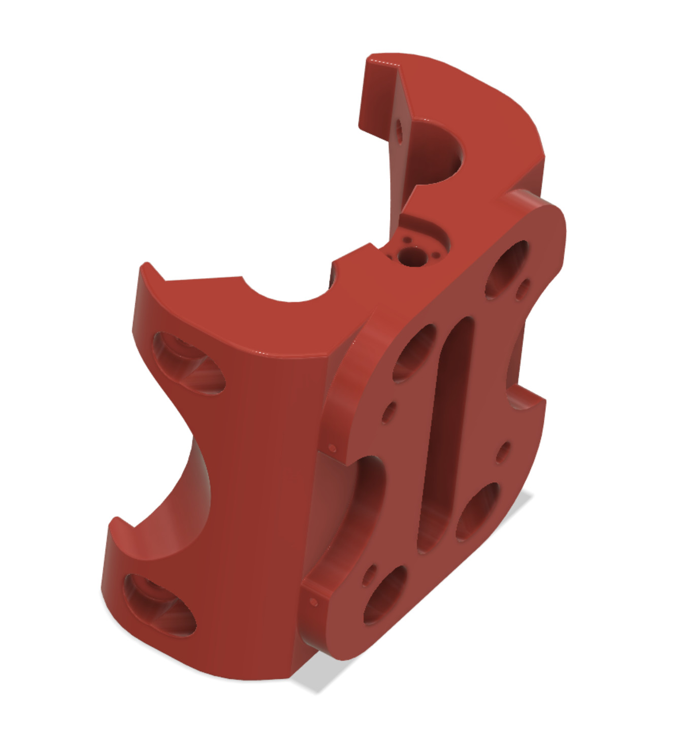
The Z-core redesign is complete. Simulated mechanical loading shows that it will be extremely sturdy. I added some side “pockets” and holes so that I can “dock” things into the Z-plate without touching my spindle. This should allow an independently actuated dust collector shoe that can lower itself to the work surface using a 3D printed rail insert, or attachment of air nozzles, etc.
4 Likes
Nice design! Looking forward to see the rest.
1 Like
Very nice stand for your router table.
I have a similar problem for my small table saw.
Do you have the possibility to share the cutting drawings in dxf format, so I can adapt them to my measurements?
I would appreciate it very much
Thanks
Paolo
Sure. You can find it here. I just uploaded it.
2 Likes
Many thanks.
Have a nice weekend
Paolo
I modified the core design so it can be printed in two halves and bolted in separately. With the X axis assembly being a buttressed design, it made sense to just extend the side plates a bit forward and run a bolt through the side of the core into the plate on either side, as well as through the back plate.
Load testing shows this will be stronger because it spaces the bearings further apart, vertically, which will reduce load on the printed parts and transfer it instead to the three pipe gantry.
Parts are almost done printing, and I’ll be ready to do the initial wood cuts for the gantry assembly this week.
1 Like
Hi again,
thanks to your drawings I did a resizing to 850 mm height, (see the annex picture)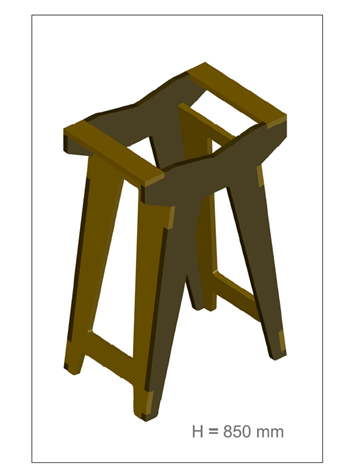
Suddenly I realized that my MPCNC working area is “only” 750 x 500…
Therefore I have only two solutions:
1 - start producing the Lowrider
2 - make the cutting in two times and moving the ply after half of the cut.
I will try to go for the second solution (it can be applied directly)
Thanks again
BR
Paolo
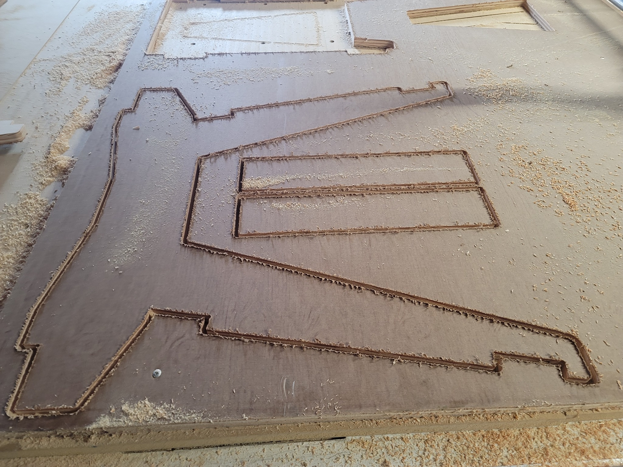
If you’re going to go with solution two… might I make some suggestions?
Screw guide rails on each side of your workpiece parallel to each other and one of the axis. That way you can make sure you’re sliding it straight.
Use a registration hole in the cut-off area somewhere. Have the machine drill the registration hole last during the first part of the cut. Then when you create the gcode for the second half of the cut, have it start from the center of that hole. This makes it easy to align the router to the workpiece before starting the second part of the cut.
1 Like
Thanks, that is more or less what I will do.
I will use centering holes as shown in the picture.
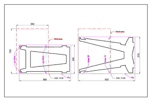
The holes will be 5 mm deeper than the cutting Ply, so I will have 5 mm holes in the spoilboard for the centering pins.
BR
Paolo
2 Likes
Looks like a classic case of: If a little is good, more is better, and too much is juuuuuuuuuust right! ![]()
2 Likes
Sort of… Mostly a case of friend with machine shop is using everything I learned on the MPCNC to build himself a giant CNC table with 4 heads (water jet, laser, mill, plasma) and has asked me for assistance with the programming of said machine and training of his minions in exchange for building me a machine table with helical rack/pinion drive and gantry system. I just need the motion/control/spindle systems, and the wife approved. It was a deal that could not be turned down, especially with the cost of linear rails and rack and pinion. I need the speed/torque in order to move forward with home business plans.
His crew doesn’t have time to devote to getting the new machine going, and none of them, including him, have experience with CNC machines on that scale or with that kind of speed.
The LowRider will be reconfigured into a MPCNC table top design since I already have all of those parts printed.
2 Likes