I wasn’t planning to get a laser for another couple of months so I wasn’t paying attention to anything I would need for a laser. However an opportunity has come up that I can’t pass up. My MPCNC is my own. I own it it is at my house. The company I work for now has need to get some foam cut for several tool boxes we are setting up. After these we will have more needs as well. They were going to contract this out and pay money. I offered to make the cuts for them if they buy me a laser for my MPCNC. So I need to know what should I get? I think I need a laser, power supply, and something for PID. (I might as well get the good stuff) With that said if I want to eventually etch aluminum, cut EVA foam (Like Steve), Cut wood what power of laser should I get? Is there a disadvantage to getting a stronger 15 (heat or beam width) watt laser as apposed to a 3 or 4 watt? I admit I have not started researching this at all yet so if you want to point me to some write ups I will gladly read them.
Ok, I have done some research on the subject now and I think I have some ideas of what I should or should not do. I was reading through all of these:
How to build a laser for PMCNC
I have learned that there isn’t really a PID for lasers. My bad. Stronger lasers are usually required for better burning but focus, air flow, and current applied to the laser diode can make a difference. Lasers are connected to the fan pins on the boards for on and off control.
Here are the questions I still have:
- If you are cutting something should you lower your Z on multiple passes to keep the focus?
- Does lowering the fan speed from 255 to say 125 work to cause the laser to burn at half power? Will that cause the laser driver to work harder or burn out?
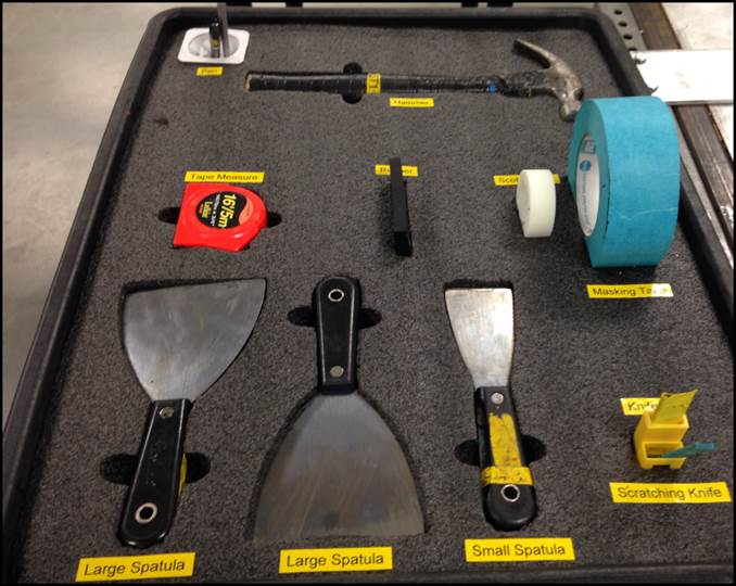
- Is it possible for me to use a laser to cut foam like this? Or is this too thick?
- Does Estlcam create laser related g-code?
So I think I answered one of my own questions. TTL means it is a digital laser. Full power on or full power off. No analog for 50% power. So in our situation if I want 50% power I set the fan to only be on for 125 of the 255 cycles per second. Therefore the laser is only on 50% of the time giving me 50% power. (roughly) Does this help improve the life of the laser?
Hey Aaryn - just chiming in to subscribe (I know I could have just clicked the link above) but also to share what I find. I just got a surprise in the mailbox that is telling me it’s time for me too to think about getting the laser set up going for the MPCNC.
I know you’ve seen this before but it’s what Google presents when searching “Laser Conversion MPCNC”. These guys only have up to a 7w laser but I have a feeling they are proven.
https://jtechphotonics.com/?page_id=3819
My needs/wants: to cut thin ply, cut acrylic sheet, to photo etch (wood burn) and whatever else a guy can do with a laser CNC. Oh, and to have a real life “frickin’ laser” to play with ; )
I’m enjoying the router cuts from the Dewalt but have been really thinking I’d love it to be quieter. Faster would be a bonus but I don’t know how fast the lasers are compared to a cutter (homework to do). Sure the laser is over the top but I think it’s a better investment stepping stone than a spindle for me which would still be louder than the laser. But I’ll do my homework. Maybe it’ll be a spindle for me, maybe a laser. And maybe if it’s a laser it’ll mean a standalone, smaller machine instead of a conversion.
I could be disappointed to learn that I can’t get this stuff to Canada too…
OptLaser does have a PID for the laser module. LPLDD-5A-24V-PID I have the 10amp version with the PID cooler hooked up. I don’t know if you really need it, I’ve seen setups with my diode that don’t use a cooler.
Yes, and No. Ive done it both ways depend on what you’re cutting.
Now TTL does confuse me. What I’ve read and videos I’ve watched, has cycling the laser on and off to vary power with TTL. The videos show the laser blinking. I have 4 TTL drivers and they don’t blink like I see in the videos. I don’t have a O scope, so who knows. Whatever magic makes them work, they do, and it’s by design so I don’t think it hurts the diode.
I would think so. For the thick stuff you’ll probably need to vary Z. Between Feed rate and power you should be able control the cut depth pretty well.
I use Inkscape and the J-tech plugin.
Please make sure you have the proper ventilation set up. Some of the stuff getting vaporized can be nasty. I have a Shop Vac that discharges out side and I wear a respirator.
Thank you both. I am so stoked to get to play with a “Frickin Laser beam”. I might need to make a shark decal for my MPCNC.
Yeah from what I read the Analog lasers use a PID and the digital lasers use TTL. From what I understand the Diodes are the same it is just the drivers. I could be wrong.
Steve excellent thought on the ventilation. I was going to use my current shop vac setup but it currently recirculates the filtered air back into the garage. That works for dust and wood chips but it won’t do for fumes. I’ll get the extra hose I need to pipe it outside. And I will use a respirator. Thank you!
I decided to buy this laser. Since my company is paying for it I went with 15 watt. But not too extrememly expensive to make them regret buying it for me. Only one review and it was complaining that there is no documentation. Since I have read through a few of these write ups on how you guys built your own I think I am comfortable with a lack of documentation from the manufacturer. Normally I would want to buy all the parts and build my own so I could learn how to do it but I feel like I am in a bit of a rush to get these cut for my company. So I just bought a set.
I can't say anything about quality, but on China's "amazon" aliexpress 15w ttl laser costs about $175-200 now (because of 11.11 ssales).
But if company pays... )But you have to read customers feedbacks. It’s not rare that on aliexpress declared power of a laser is not real. Or the diode could be overloaded and then degrades too fast
Yup, that controller looked familiar. Got one in my box-O-parts, it didn’t come with connectors for power in and TTL. Think I have some of them around too. If you need the connectors let me know I’ll mail some out.
edit: Just looked at the power supply you’re probably going to need a female connector for that too if you don’t want to lop the end off.
Thank you for the offer Steve. I am a bit of an electronics hoarder. Got an electrical engineering degree from ITT-Tech before they went belly up. Been collecting electronics since. I probably have all the connectors I need. But I will ask if I need.
Endurance lasers! I forgot about them. Thanks for links. I will keep this in mind.
So… I have my new laser. With another on the way. I have a cheapo in front of me and a quality one from Endurance Lasers on the way. The cheapo has a switch that can flip between analog and 5v TTL. From what I understand it will be easier for me to get the TTL working. I believe I need to upgrade to a newer firmware and use some of the suggested settings to set the laser enable pin. I think I am ok so far. If I am wrong please correct me.
Here is where I am a little unsure. My control board is a cheapo I pulled off of a knock off prusa i3 clone called a migbot. The board is an MKS base v1.1. I have never had any trouble with it but long term I would prefer to stop using the heaters on it. Aka no more heated bed or extruders. They work but I have heard enough stories about 3D printer fires to want to use quality components going forward. So this board is still great for anything that needs 5 motor drivers. I want to use this board for a dual end stop laser cutter. What pin can I use to control the 5v TTL? Looking at this pin layout I think I can use D19. That is the pin for Z Max on this board. But I am not sure how I can tell if D19 will support PWM. Other than trial and error is there a way I can know? Does anyone have any other suggestions?
[attachment file=“Board Pin outs.jpg”]

If you don’t use your cnc as 3d printer you may use d9 and control laser with m106/m107 gcodes. I guess the fan switched by mosfet to the ground, so probably you can take “-” connect it with pullup resistor to +5v and achieve pwm ttl output
Oh this link is gold! Thank you!
This helps explain so much! So I could still have my normal fan pin work with a 12 volt to control an actual fan. Then use the ground pin from on of the unused extruder heater connectors to control the laser. Like you said plug the + wire into a +5volt somewhere else on the board.
Then I control the fan with M106 S0-255 and the laser with M106 P1 S0-255.
The resistor is optional but recommend to prevent the laser from turning on when the board boots up.
Thank You!
I do not think that will work. The 12v ports should always be grounded and the + will be mosfet switched. You should have a few extra 5V capable pins, servos pins, something on your board.
Sorry, Ryan, but at least for ramps your expectation is not true:
[attachment file=“RAMPS1_4schematic.png”]
Honestly i’m also not fully right - it connected to 12v by led+resistor (they can be cutted)

No, i didn’t say to connect “+” wire of the d9 connector to somewhere. Especially don’t connect it directly to +5v, you may damage the board.
You need “-” wire and ensure woth tester that it not has indirectly +12v via a “led+resistor” on the board (like ramps has). 12v here may damage laser control board
Yes thank you for the clarification. That is what I meant but my words were not very clear. Connect the - pin from heater 1 to the resistor and then that goes to the laser - TTL.
Then then the + TTL from the laser goes to a +5 v elsewhere on the board.
The heater + 12 V is not used at all.
Ryan - This is from years ago in my ITT-Tech classes for Electrical Engineering. (A degree I never used except as a hobby) My Professor explained how most ICU (Integrated Circuits or Chips) are designed to handle more of a load through the negative pin than they are the positive or logic pins. So you could draw more current through the chip if you use a positive source and then use the logic chip as your ground. Instead of trying to push a positive voltage through a logic chip and have that connect to a negative source.
My memory could be wrong but I do know that I have seen consumer electronic circuits that are built to have logic control the negative pins more often than I have seen the positive pins. So counter intuitive. I will check my board. It will be easy to check. Just use an Ohm meter between the heater - pin and - pin from the 12v power supply. If that is an open connection then you know logic on the board is wired up to control - pin. If it is close to 0 then the board is probably wired to control the + pin. In which case i will need to figure out a voltage divider as well.
A voltage divider did not work a few years back when we tried, it is much easier you just have to figure out what pin to use for 5V, It is even built into marlin now. I have never used or seen your board so I can’t really help, but just find a 5V capable pin. Doing it the right way is actually the best way.
I’d try to use A11 r A12 on that board, they should be 0-5V outputs, driven using the matching +5V and Gnd pins. That’s on connector XS3. If that isn’t going to work I’d switch to connector XS6 and use the digital outputs there, D50, D51 et al.