New 610 x 460 MPCNC Primo Build in UK

Hi from Doncaster in the UK,

I decided to annoy my good lady by embarking on a new (2nd) hobby. I already have two Prusa Mk3S+ 3D printers, but really fancied having a play with a CNC machine. Ignoring the cheap Chinese machines, when I looked at various options on-line, I was looking at the best part of £1500-£2000 for a decent specification set-up. Then I found out about the MPCNC and the rest, as they say, is history.

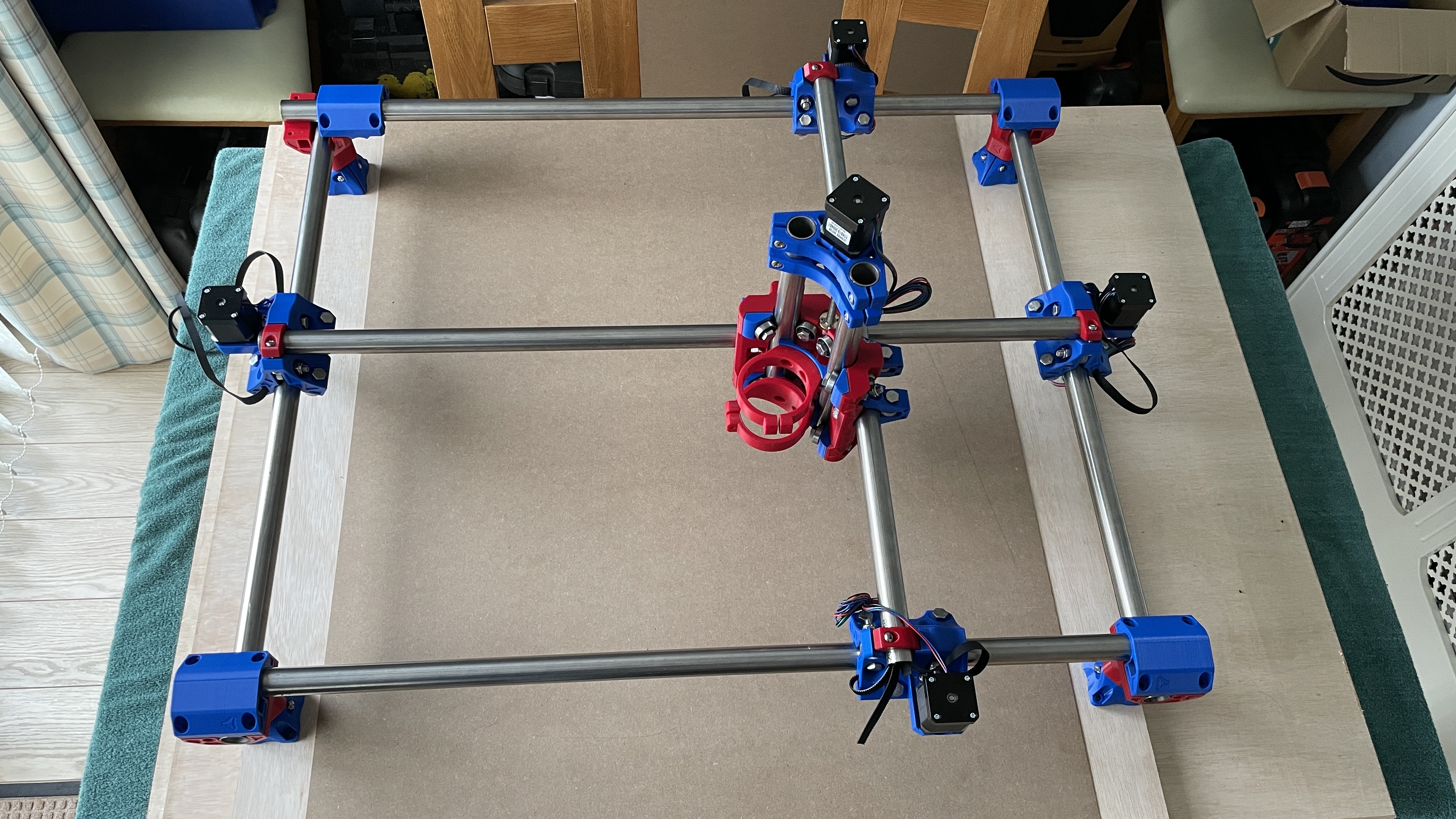
I decided to go with a 610 mm x 460 mm x 81 mm (24" x 18") workspace and started collecting the necessary hardware. I had to buy the SKR PRO 1.2 and screen direct from Ryan, as I couldn’t find one anywhere in the UK (and I didn’t want to order from China).

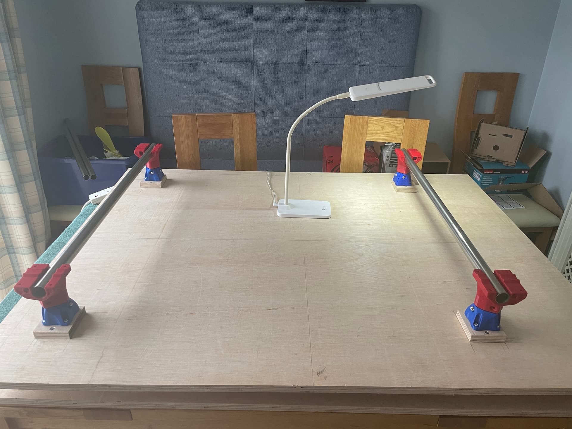
I set my two Prusas to work, printing the all the parts, which turned out very nice indeed. The longest print was the core (with Ryan’s infill settings etc) which took just over 18 hours. I bought some 25.4 mm stainless steel tubing with a 1.5 mm thick wall. Although ordered at the required lengths, all the pieces were slightly too long by varying amounts (2 or 3 mm). Fortunately, my son’s father-in-law has a great DIY workshop, and we were able to grind them down to equal lengths and square the ends, as well as accurately drill the router mount holes.

I have made a purpose built table using recycled wood from our recently replaced bed base. I’ll not frighten any serious carpenters here by showing my handiwork, but it is stable and will easily support the MPCNC.

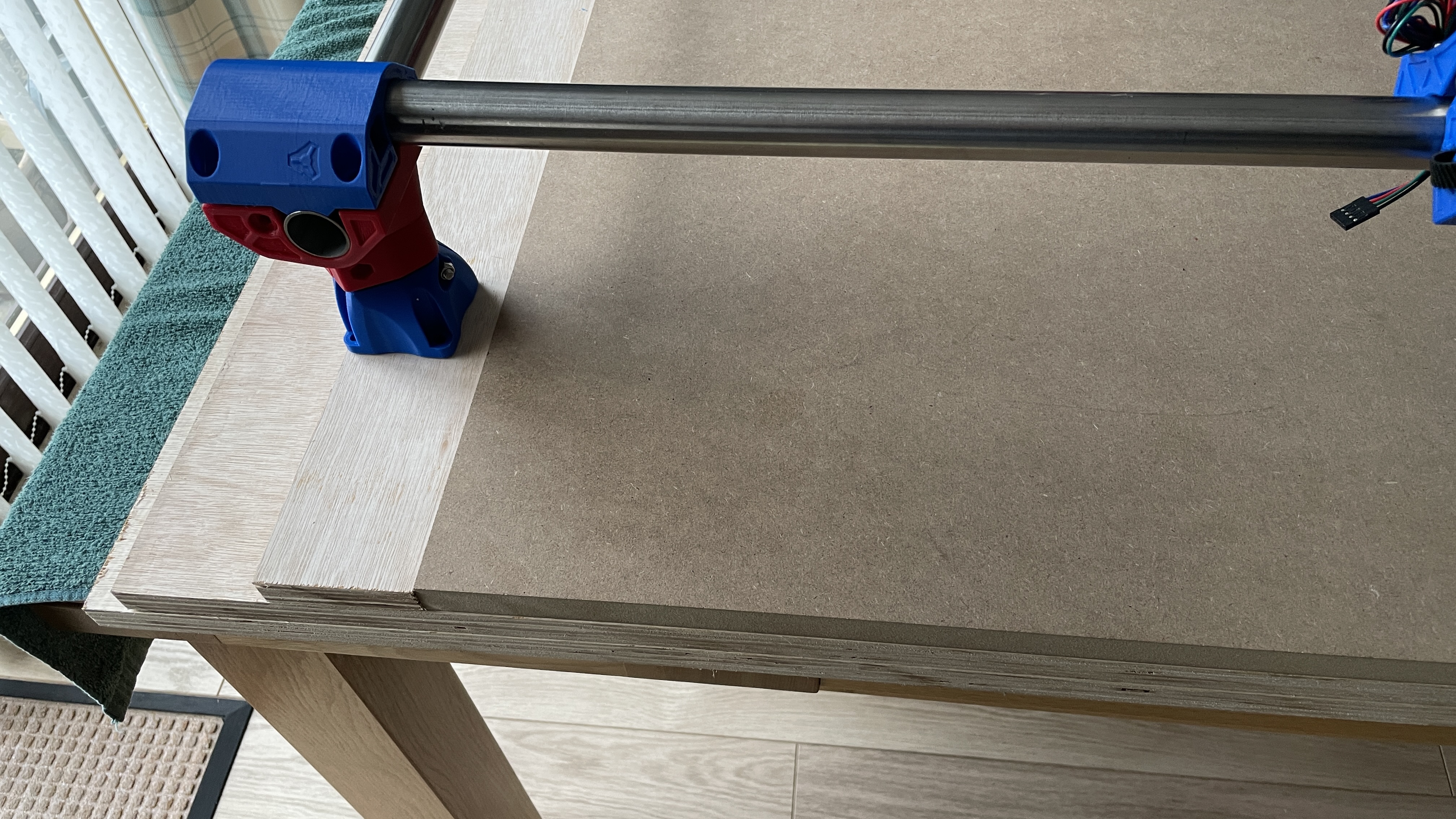
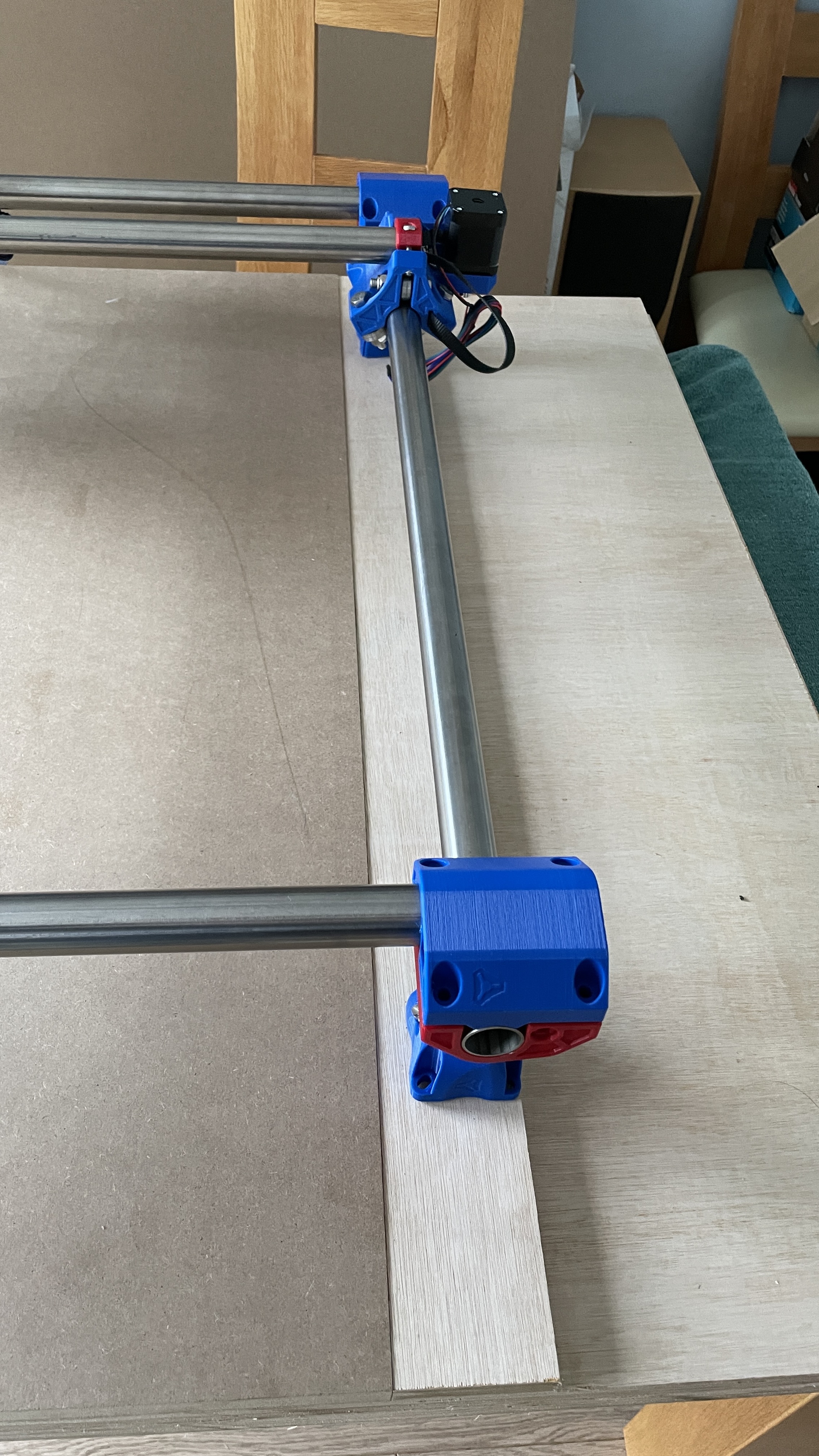
Now to ask for some advice. I am using a sheet of 18 mm plywood as a base, with 2 strips of 18 mm either side to support the legs. I then plan to slide a sheet of 18 mm MDF for the spoil board between these support strips and lock it in place with some end stops blocks at the back and some turnbuckles at the front.

Is my idea a good one, or is there a better way I can do it? I did think of adding another layer of 18 mm plywood under the feet to lift them to 36 mm from the spoil board.

I also can’t decide whether to use M5 inserts or T-channels for clamping the stock pieces, or what spacing to use here.

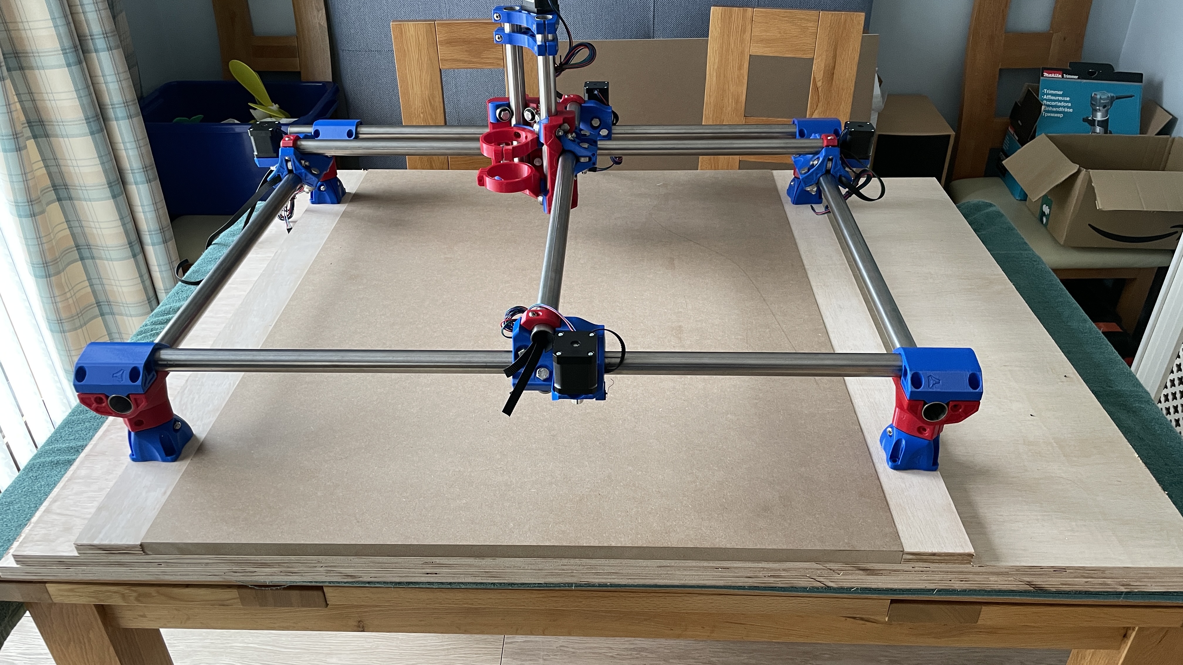
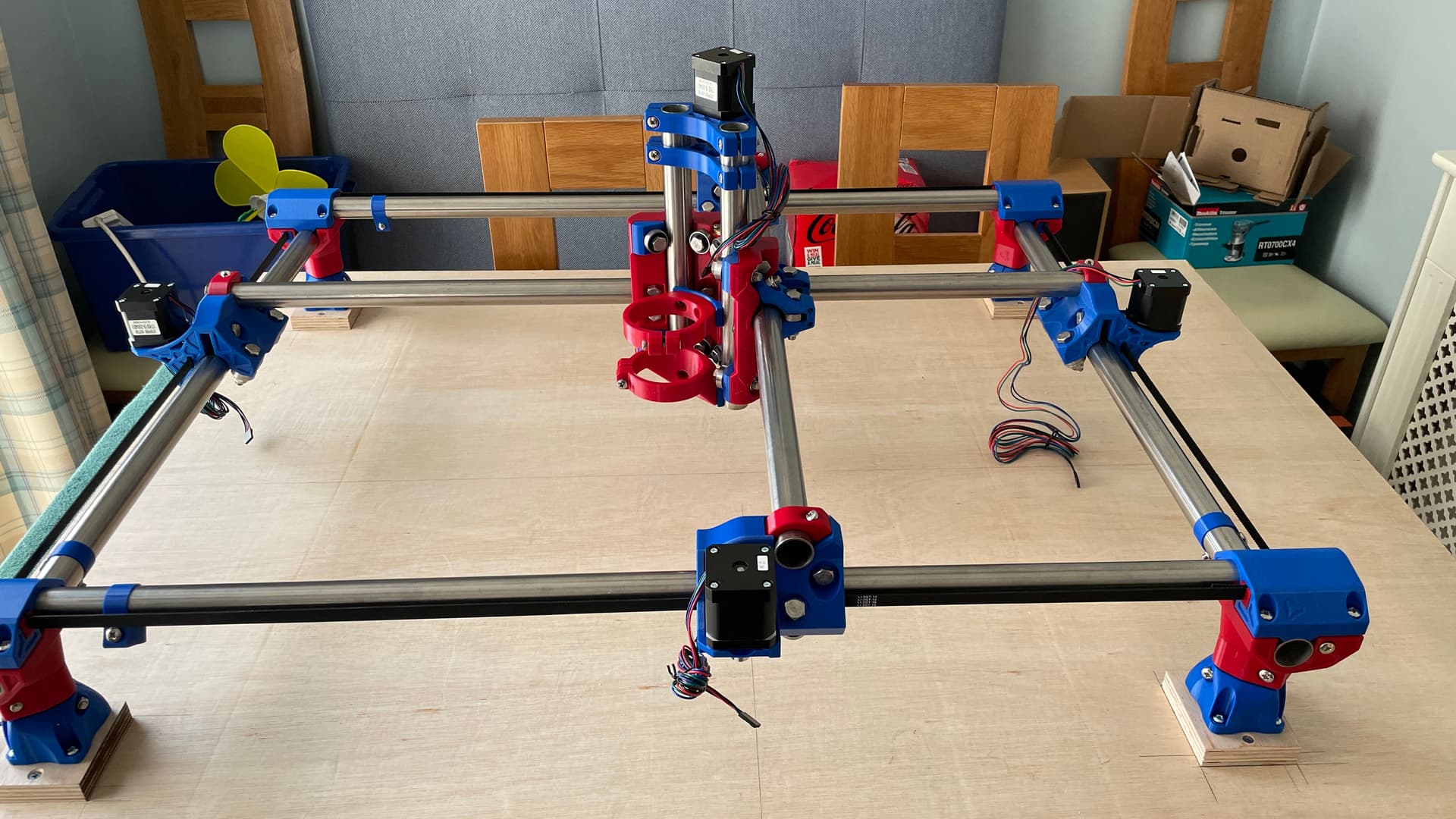
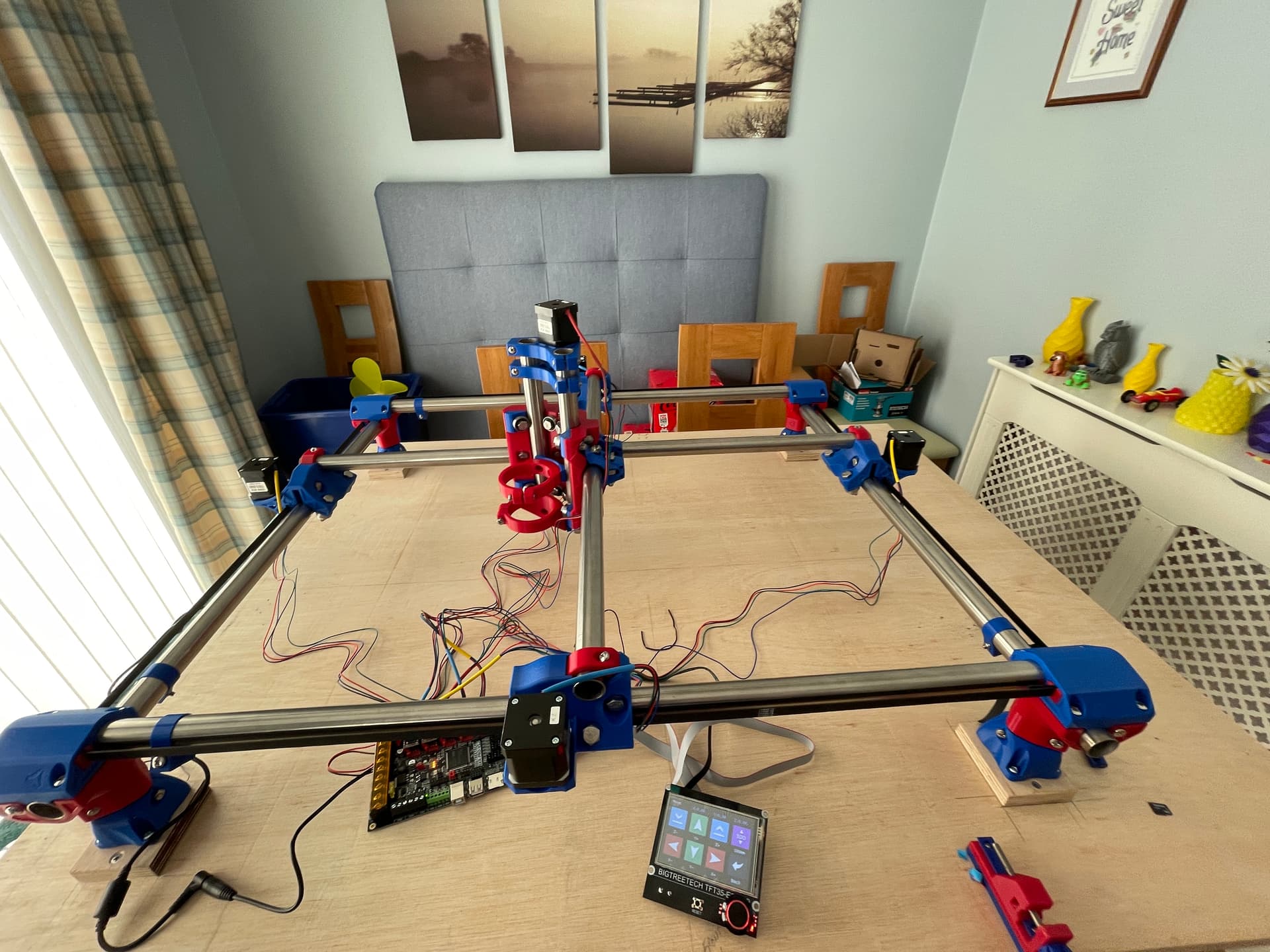
I have done a ‘dry’ build on the dining room table (yes, I have my wife’s permission) and everything seems to run smoothly, considering nothing is bolted down yet. Please note that there is a second sheet of plywood underneath, which is a spare for use elsewhere.

11 Likes

It looks good to me. But there is a lot of the spoil board area the bit canteen reach. I would just put some countersunk screws to hold it down. You don’t want the spoil board moving.

3 Likes

If you sink threaded inserts into the plywood base, you could use brass flat-head machine screws to secure the spoilboard. As @jeffeb3 notes, there’s a lot of area the machine can’t cut into, so if the screws are out there material doesn’t really matter. I suggest using brass hardware inside the cutting envelope since the machine tool shouldn’t have trouble cutting through it if there’s a programming error, missed steps, or other machining mishap.

Another option would be to run 1/2" tall aluminum t-slot channels across the build area with 3/4" thick MDF panels in between. Then you can resurface the MDF a couple of times and still be above the channels, and just replace it when it gets too chewed up. This gets you flexible placement for hold-downs with t-bolts, etc. in the channels, but also allows for driving in a screw (or plastic nail) wherever you might need a little extra hold.

@jeffeb3 & @ttraband, thank you for your comments and suggestions. I’ve decided to reduce the size of the spoil board, and I’m making the feet support blocks smaller, as the wood between the feet is just wasted.

I’m also going to make an enclosure to hopefully contain the messy stuff and, with some added insulation, reduce the noise level a bit.

2 Likes

Looking forward to seeing how it goes.

Hi Roy,

I’m in the printing process my self (Just one printer)
How did you get the core down to 18 hours?

I’m using a 0.4 nozzle, 0.2 layer height, 5 walls, 4 top / bottom layers and 50% infill.
80mm speed (40mm on the surfaces and one outer wall).
The trucks took 15 hours.

Upping to 70% and adding another wall for the core takes the print time upto 34hours…

Hi @NoseyMole,

I’ve just checked my g-code file and I printed using a 0.4 nozzle with 0.3 layer height, 70/30/70 infill with 4 top & bottom layers and 3 perimeters. First layer speed was 30, infill 80, and 45 for perimeters. This came to 18 hours and 5 minutes printing time.

Except for the infill percentages, the number of perimeters and the top & bottom layers, the settings were more or less default Prusa settings for PLA. I used eSun PLA+ (rightly or wrongly).

I did slice at 0.2 with the same settings, and it came out at 25 hours and 4 minutes.

Good luck with the printing.

Perfect thank you.
I might do the core at 0.3.
I did the variation in the infill but I couldnt identify any section of the core that would need less structure.

(I’m usung eSun PLA+ too)

1 Like

Most of the MPCNCs I’ve seen use a similar building technique to the one you are using here. This is how I built my original Burly MPCNC.

At some point (it is recommended that you put some hours in on your machine first), you will want to surface your spoil board. Surfacing is just cutting the top of your spoil board off using the router so that you can be assured that the surface is parallel to the plane of travel of your router. If the spoil board is bigger than the working area of your machine, then you end up with a depression in the middle of your spoil board.

For me this depression made it difficult to use oversized stock in my machine. Using oversized stock is mostly a stock preservation strategy for me. I did it occasionally when using the router, but I now do it frequently with the addition of a laser module to my machine.

To get rid of this depression (when I upgraded to a Primo) I installed my spoil board on top of everything, and sized it to the working area. For your machine, you can simply cut the long strips that the feet sit on down to blocks. My solution was to use legs 18mm longer, and mount the legs directly to the base board. As for sizing and positioning the spoil board, you can get those by pushing your router around and locating min, max and distances traveled, plus the calculator you used to size your machine will give you the working area. You don’t have to be precise with size or position since surfacing bits tend to be larger (25mm) giving you some 12.5mm slop in both size and/or position.

@robertbu, thank you for the advice. I am aware of the surfacing option and it is something I plan to do once I’m up and running (as you suggested). I’ve just cut my spoil board down to a 760 mm square - but I am listening to your advice and may resize it again to fit the working area.

I am planning to cut the foot support strips down and will probably double stack them to give a bit more clearance, and I don’t believe this will affect the rigidity of the machine.

Thanks again.

I’ve made some progress this week. I managed to get my table finished, apart from attaching the MPCNC platform - that’s still on the dining room table.

It took a while to work out exactly where to put the blocks for the feet - and I still got one slightly wrong, but it works.

I spent Wednesday afternoon/evening and Thursday building the machine as per Ryan’s instructions. Took me some time to get it square and was less than 1 mm out on the diagonals. Squaring the frame was a bit difficult too, as I couldn’t easily get to one of the adjusting bolts on the trucks. I ended up removing the stepper to gain access. I got there in the end, though, but I don’t think it lasted long (more in a moment).

Once I finished the mechanical build, I set about the electronics. I assembled the SKR Pro V1.2 with the 2209 drivers and attached the TFT. Everything powered up fine, and I didn’t set any smoke alarms off. My steppers have 4-pin Dupont connectors on the end, and I found that they will fit into the JST-XH connectors on the SKR well enough for testing. I have some proper XH connection cables arriving which will be terminated in the electronics box to GX16 connectors.

Once I got everything wired up (still no smoke), I tested the movement. This didn’t go quite so well, as I initially thought I had either a dodgy 2209 or the SKR had a problem. Only one motor on the Y-axis was being driven. So the one driven motor was dragging its opposite number along, which pulled it at some awkward angles - I’m guessing my time spent squaring everything was wasted, and I will have to do it again.

After swapping drivers and motors, it was still the same. After a little head scratching, the penny finally dropped. I have connected the motors to separate drivers and of course, I was running the default firmware that Ryan ships with the SKR, which is for series motors. Once I flashed the correct firmware, everything was OK.

I have soldered the end stop switches using some speaker cable that I had lying about - a bit overkill, but I didn’t need to buy anything else. I’ve coloured-coded my cables to avoid confusing myself once I get to the electronics box.

I’ve thoroughly enjoyed this project from start to… well, as far as I’ve got up to today. I won’t be able to cut wood until sometime in March, as my new workshop/shed doesn’t arrive until March 1st.

6 Likes

A quick video of the machine’s initial awakening.

IT LIVES!!

1 Like

Can someone please confirm the orientation of my core please? I’m wanting my X0,Y0 location to be the front left of the MPCNC (bottom left, as you look at the photo). The end stop switches are located at the front of the Y axis trucks and on the left side of the X-axis trucks.

Also, should there be (or do I need) an end stop on the Z-axis? It seems that it is possible to drive the tool mount straight up out of the rollers. I have spent an hour searching for the answer, but couldn’t find anything definitive.

Thank you.

On these machines, endstops don’t limit motion. They only are used during homing. You can use a touch plate to set the Z=0 on the top of the work. But no endstops on the MPCNC Z axis.

Hi @jeffeb3, thanks for the reply. I just wondered about the Z-axis running away with itself.

Can you please confirm that my core is mounted correctly for the given 0,0 point (front left)?

Thanks

It can run away. Just try not to do that :slight_smile:

It looks right to me. I don’t actually have a primo, so I let other jump in and answer those kinds of questions. The core looks right, but I am not familiar enough with the truck geometry to say if they are flipped or whatever. I didn’t even look.

But that close left corner is the easiest place for the 0,0. So it is the most common.

1 Like

Thanks once again for the reply. I’ll start a new thread with my core question, as it’s likely that it could be overlooked in my build thread.

Looks assembled correctly to me. A z-stop is not a requirement, but it can be convenient to have for a few reasons. As you mentioned, yes a z-stop prevents you from over running the z axis. It also allows lifting all the way up before homing, which may save some bits from crashing into clamps some day. Also, having absolute position allows for semi-automated tool changes; that alone is the reason most ppl add them to their rigs. I designed this mount for a z-stop switch on the Primo:

1 Like

Thank you for the information @truglodite - I’ve saved your switch mount to my ever-growing Thingiverse CNC collection.

As I’m just starting out on this adventure, I’ll stick to a ‘standard’ build until I have progressed up the no doubt, steep learning curve.

1 Like

Yes, the way you have it set up the x0y0 is in the lower left hand corner of the machine as in the picture. Your stop blocks locations appear to be correct