New Build in Halifax, Nova Scotia

2020 06 29

Hi!

My MPCNC is finally coming to an operational state (I hope). I started building this machine over 2 years ago. I bought everything, put it mostly together, and then got side tracked and left the MPCNC alone for most of those two years.

I’m now retired and that and covid gave me incentive to get this machine working. There have been quite a few changes in my down time on this project.

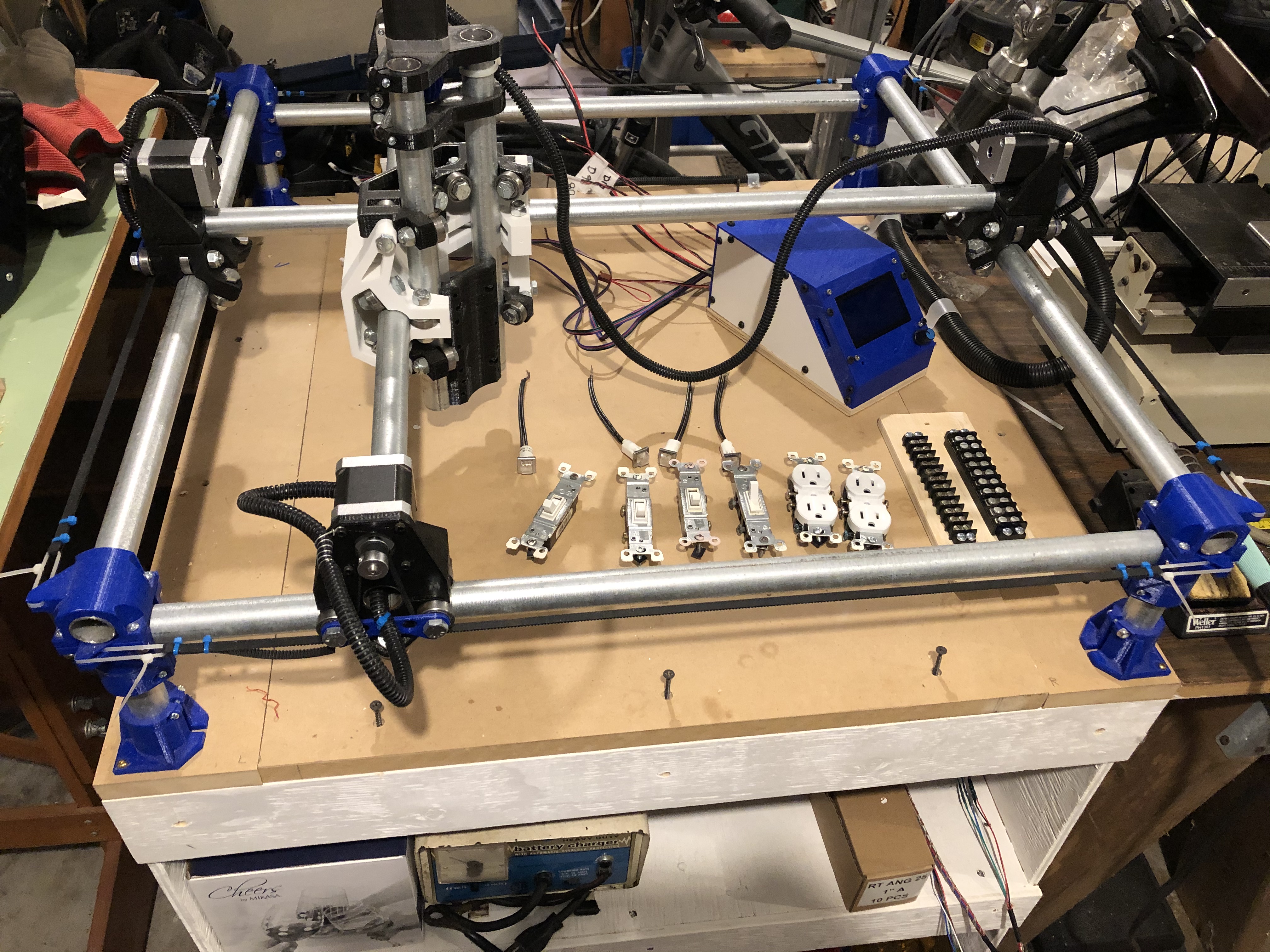
The machine I’ve built is pretty standard. It’s roughly 30" square, uses the 1" conduit, has an Arduino Mega 2560 and RAMPS 1.4 board with 8825 drivers.

The steppers were a bit of a departure from the norm. They are 3V, 1.7A motors with 400 steps/rotation. I’ve wired X and Y motors in series and I run from an old ATX PC power supply at 12V, 10A.

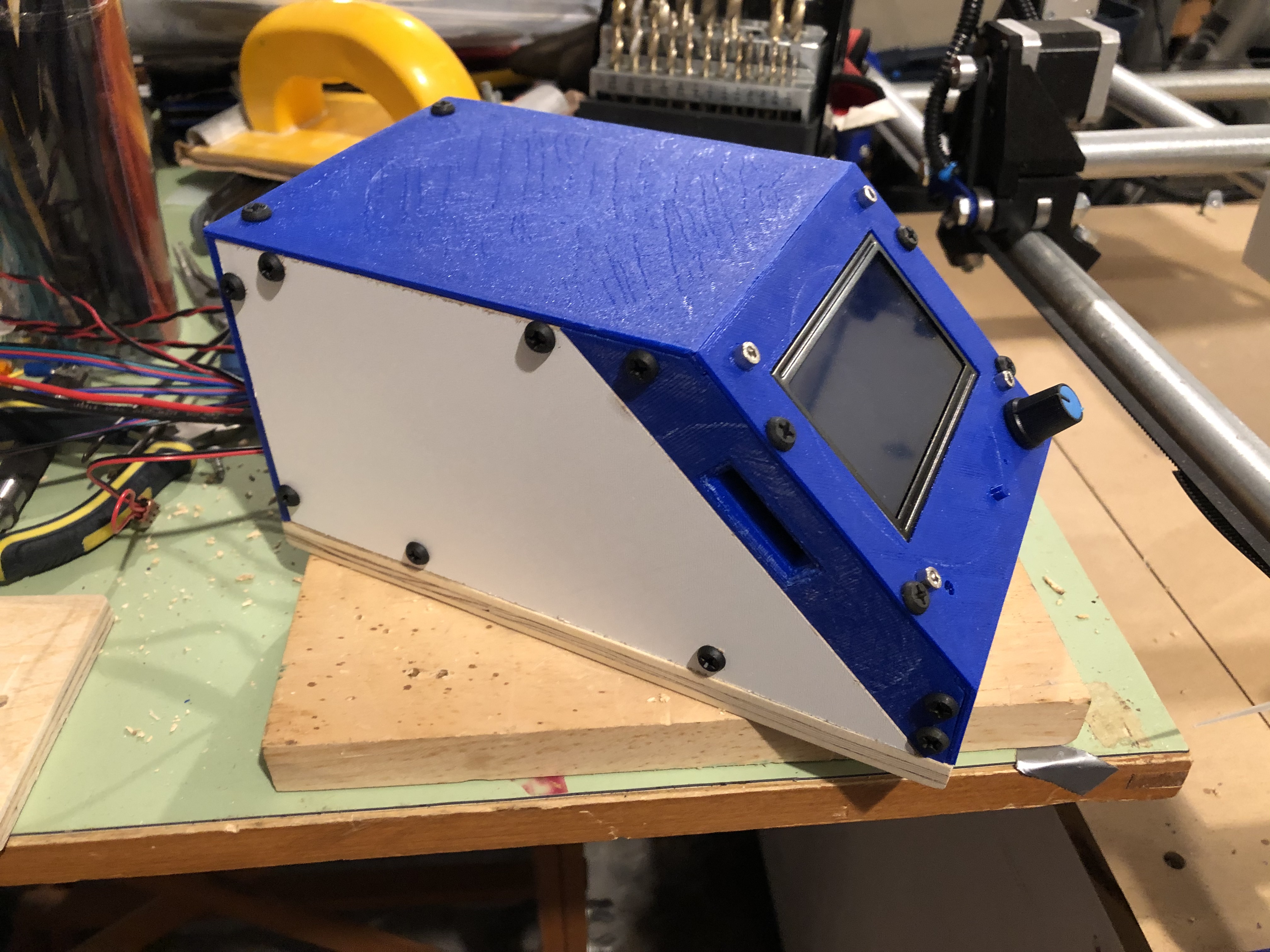
I designed and printed a box for the Arduino and RAMPS with the ST7920 (128x64) display.

The controller, power supply, and 110VAC wiring is not all tucked away yet, but otherwise the machine is done and I’ve begun testing.

The MPCNC seems to be fully functional, but I have some questions about:

  1. The feed rate settings for the horizontal and vertical axes
  2. The controller SD card shows folders, but not any files (I’ve tried .gcode)
  3. Whether or not the CAM software (whatever it turns out to be) will properly limit the Z feedrate
  4. The XY motions are only about 62.5% of the expected motion. My steps/mm must be wrong, but I am not sure why

Here are some pictures of my build in progress.

The first is the general view, which also shows the cabinet on castors that I built for the MPCNC.

The second is a top view of the 3D and wood controller enclosure and the binding post connectors for the X, Y, and Z motors, the D8, D9, and D10 FET switches, the fan, and the 12 V PS.

The final view is an oblique view of the controller housing.

My first questions:

I tried to draw the crown using the 12mm/sec file from the V1 site. I immediately encountered problems with doing this. The pen went down, then down, then down…

It turned out that the F[rates] were too high for my Z axis. By testing I found that F250 was the maximum safe rate for my system.

I think this is because the 400 steps/revolution of the motors means that my max rate is about half the safe rate for systems with 200 steps/revolution. Is this correct?

Any Z feed rate higher results in unpleasant sounds that clearly indicate missed steps. The crown file just makes the Z motor whine with little or no movement on the lifts; hence, it just gets deeper and deeper with each engraving part.

To be honest, I don’t see how the 12mm/sec file could ever work with the F2100 rates, unless it is because of multi-start T8 leadscrews in current builds? (I just have a 5/16" threaded rod)

The F250 makes Z move at a reasonable speed, but should I go to 16th-stepping rather than the 32?

By the way, there is clearly no lack of torque. I’m sure my Z motor could bend the conduit or break the 3D printed parts quite easily. It nearly did till I hit the RESET.

The X and Y axes move well. I have tested rates up to F12000 and while I haven’t timed the motions it sure looks to be moving faster with each rate increment. I also tested down to F50 and this works too.

I made the following two edits in the configuration.h file. The 9070.3 seems to be correct for Z motion. I used a vernier and got pretty accurate delta-Z changes. The 8.4 max feedrate came from somewhere in the forums.

Since my X and Y motions are only about 62.5% of the expected, I’m guessing that I should have used 320 rather than 200?

/**

  • With this option each E stepper can have its own factors for the
  • following movement settings. If fewer factors are given than the
  • total number of extruders, the last value applies to the rest.
    */
    //#define DISTINCT_E_FACTORS

/**

  • Default Axis Steps Per Unit (steps/mm)
  • Override with M92
  •                                  X, Y, Z, E0 [, E1[, E2[, E3[, E4[, E5]]]]]
    

*/
#define DEFAULT_AXIS_STEPS_PER_UNIT { 200, 200, 9070.93, 200 }
/**#define DEFAULT_AXIS_STEPS_PER_UNIT { 200, 200, 800, 200 }
*/

/**

  • Default Max Feed Rate (mm/s)
  • Override with M203
  •                                  X, Y, Z, E0 [, E1[, E2[, E3[, E4[, E5]]]]]
    

*/
#define DEFAULT_MAX_FEEDRATE { 120, 120, 8.4, 25 }
/**#define DEFAULT_MAX_FEEDRATE { 120, 120, 30, 25 }
*/

Appreciate any help, guidance you can give.

That is the highest number I’ve seen. The standard rambo uses 1/16th, 4 start T8, and 1.8 deg steppers. So it is 400. 9000 is causing two problems:

  1. the cpu has to raise and lower that pin 9000 times for each mm so if it is trying to move 10mm/s, it is flipping that at 90kHz, by basically bit banging. That is going to swamp the cpu and cause lots of problems. 1/16th or even 1/8 wouldn’t hurt you and would alleviate this particular problem, but 12mm/s may still be too fast.

  2. steppers creat reverse voltage when they spin. The drivers connect the psu (12V) to the stepper coil until it reaches the current it is set for. As the steppers move faster, they produce more reverse voltage, which means at some speed, the drivers have connected the 12V straight through, and they still aren’t reaching their set current. Above that speed, the torque you get at the motor shaft is smaller and smaller. The 5/16" rod has plenty of force pushing down or pulling up. But the torque on the screw (the turning) is diminished at higher speeds. Any friction is enough to cause skipped steps.

So, one of the things you’re seeing is a list of reasons we went with the 4 start T8. If you switch, you’ll have a lot fewer problems. If you keep your current gear, reduce the microstepping (1/4 might even be fine). And then just go slow. Unless you are doing 3D carving, the Z speed doesn’t make an enormous difference in total cut times. You can set the max Z speed and it is actually honored in recent Marlin versions. But belt and suspenders is to also set it right in the CAM.

It sounds like this might be caused by 20T pulleys and those same 0.9 deg steppers. Is that right?

1 Like

Thanks for the info. I’ll take a look at the stepping again.

I ordered 16T pulleys. I didn’t count, but I will tomorrow! Mind you, I think the diameter is right for 16T. But who knows. I’ll verify it.

So, it is true that the CAM software will limit the feedrate (once set) and I generate my own gcode?

The 12mm/sec crown file worried me that this might not be the case. It seems that a few people have had problems with Z from what I can see, perhaps they didn’t have T8 lead screws either? There isn’t anything that says this file requires that.

Thanks

Between the CAM software and Marlin is the gcode. If the gcode asks for 720mm/min, then Marlin will try to reach it. If Marlin is configured for a max speed of 6mm/s, then it will not go 12, it will top put at 6.

If the gcode from CAM asks for 6mm/s and the max Z in Marlin is 12mm/s, then Marlin will still go 6mm/s.

It really should be a simple thing, but it gets complicated because the gcode isn’t completely obvious. In CAM, usually there are separate settings for XY and Z. If the CAM isn’t being explicit enough, it may accidentally send a Z movement with an XY speed attached.

I may be particularly sensitive to it, because we’ve spent a ton of time looking closely at it for years.

As for other issues with skipping steps on a T8. There are quite a few folks that get 1 start leadscrews on accident. There are also wiring problems or still people with ramps that don’t set the driver current. The premade test crown should work on anyone’s T8, 4 start, 12V MPCNC or Low Rider.

Here is am excerpt from the test crown:

G01 X77.4710 Y66.9949 Z-1.0000 F720
G00 X77.4710 Y66.9949 Z5.0000 F500
;No. 3: Engraving 3
G00 X76.6653 Y74.3955 Z5.0000 F2100
G00 X76.6653 Y74.3955 Z0.5000 F500
G01 X76.6653 Y74.3955 Z-1.0000 F210
G01 X76.6470 Y73.9675 Z-1.0000 F720

On the second line the Z goes up to Z=5. But at a speed of F500 or 8.3mm/s.

The line with F2100 doesn’t have a change in Z, so that is a 35mm/s travel from one XY to another.

It travels down again to just above to surface at Z=0.5 at 8.3mm/s again.

Then it plunges at F210, which is 3.5mm/s to Z=-1.

Then it draws, only moving X and Y at F720, or 12mm/s.

So it looks like, in this file, the Z never exceeds F500.

How do you know if you get a 1 start or a 4 start? When I looked at getting a leadscrew, all was just listed as T8 leadscrew with nut more or less.

That’s one of the problems with cheaper components; the specs are often vague or incomplete and sometimes missing or wrong.

I looked at T8 lead screws on Amazon and similar sources recently and found the same issue for cheaper items. But, I also looked at them from McMaster-Carr and other suppliers. These suppliers cost significantly more, but you get full details on the product. You can also be sure that the product is properly hardened and treated. The downside is the cost.

For me the decision is what my end use is and my risk level. In the mpcnc case, I’ve spent less than $500, including a Dewalt 611. I wasn’t sure how well the project would turn out, nor in the end how much I’d use it. Everything I bought is reusable elsewhere and I’ve already learned a lot. That alone was worth the investment.

As it happens I think the indications are good for the MPCNC, but I think that once it’s proven, I’ll upgrade it. That $200 T8 and more rigid pipe are a good place to start.

If you have it in your hands, you can look at the end and count the starts. I don’t know the best way if you’re looking at amazon.

McMaster Carr does give you what they spec’ed, but you can make a few mistakes on amazon and still save money. The commodity nature of these parts are a key part of what is driving this 3D printer and now the CNC revolution. I have had an issue with a poor leadscrew. I contacted the seller and they sent me two new ones, and let me keep the first one.

2 Likes

OK! Bitten once again! They are 20T pulleys!

Those Buxxxxxxs! Ah well, that explains the motion being off on X and Y. At least the pulleys seem decent quality.

Just goes to show you how you don’t always quite get what you order. The last time that happened I ordered variable capacitors. I got some that looked right, but were totally different capacitance values.

Thanks again for the inputs.

I’m going to start by going to 1/16 stepping. This should bring me in line with the original MPCNC where the steppers were 1.8-deg vs. my 0.9-deg.

From my tests, I should then be able to use F500 for vertical motion. The X, Y rates seem to be fine already anyway. Together this should give me a bit of compatibility at least with the original MPCNC and some gcode files. At least the crown should draw at that point.

I’ll post how it goes…

1 Like

Maybe, maybe not. There are two things at play here. Going to 1/16 will remove the CPU bottleneck, but not saturating the voltage due to high speed. To fix the second, you either have to move slower (by F250, or replacing the allthread with leadscrew) or increase your supply voltage (24V is a common next step, but 15V might be enough to give you satisfying headroom).

Yes, you may be right, but I’ll do one step at a time and see what happens.

Actually, I’ve been wondering why I should microstep at all? I know it makes the motion smoother, but reduces torque. Resonance is the usual advantage, but I don’t know if I’ll encounter that or not.

Without microstepping, I’d still have 283 steps/mm in Z and 10 steps/mm in X and Y. Given the flex of the MPCNC the 0.1mm accuracy should be fine.

I would leave the microstepping on X, Y.

When microstepping, you’re getting very similar torque, and when you land on the full steps, it is exactly the same, so it really doesn’t have much impact. But on the XY, you will definitely notice the difference on a sweeping curve and in that 0.1mm, you’ll be instantly accelerating and then stopping.

OK, fair enough. Like I said, one thing at a time. I’ll try the 1/16 stepping now.

You were 100% correct! 1/16 stepping did not quite get me there. I can now handle F450 safely on the Z axis. Generally all the motions are better and the motors sound good. They have nice clear emissions, until they miss then you can hear clicking and snapping in the tones.

F475 mostly works, F480 doesn’t.

So, after supper, it’s 1/8 stepping!!

Well, changing the stepping rate isn’t going to do it. 1/8 stepping was worse than 1/16. I’ve gone back to 1/16 now. I found that 450 mm/min was not 100% reliable. I’m down to 425 now. I might not be able to maintain that once the router is loaded.

So that got the microstepping out of the way. I guess the voltage is the next step as you said; however, since that requires two power supplies and mods to the RAMPS board, I may try to live with whatever I get for awhile.

I understand that you have to remove D1 from RAMPS to go over 12V. I don’t know if that is the only change–other than adding the power supply for the Arduino.