A few years ago I bought a chinese “T8 CNC engraver” build of 2020 profile that has shown it’s limitations in workspace size, speed and spindle power. But it was (still is) a really fun and educative toy that finally brought me here.
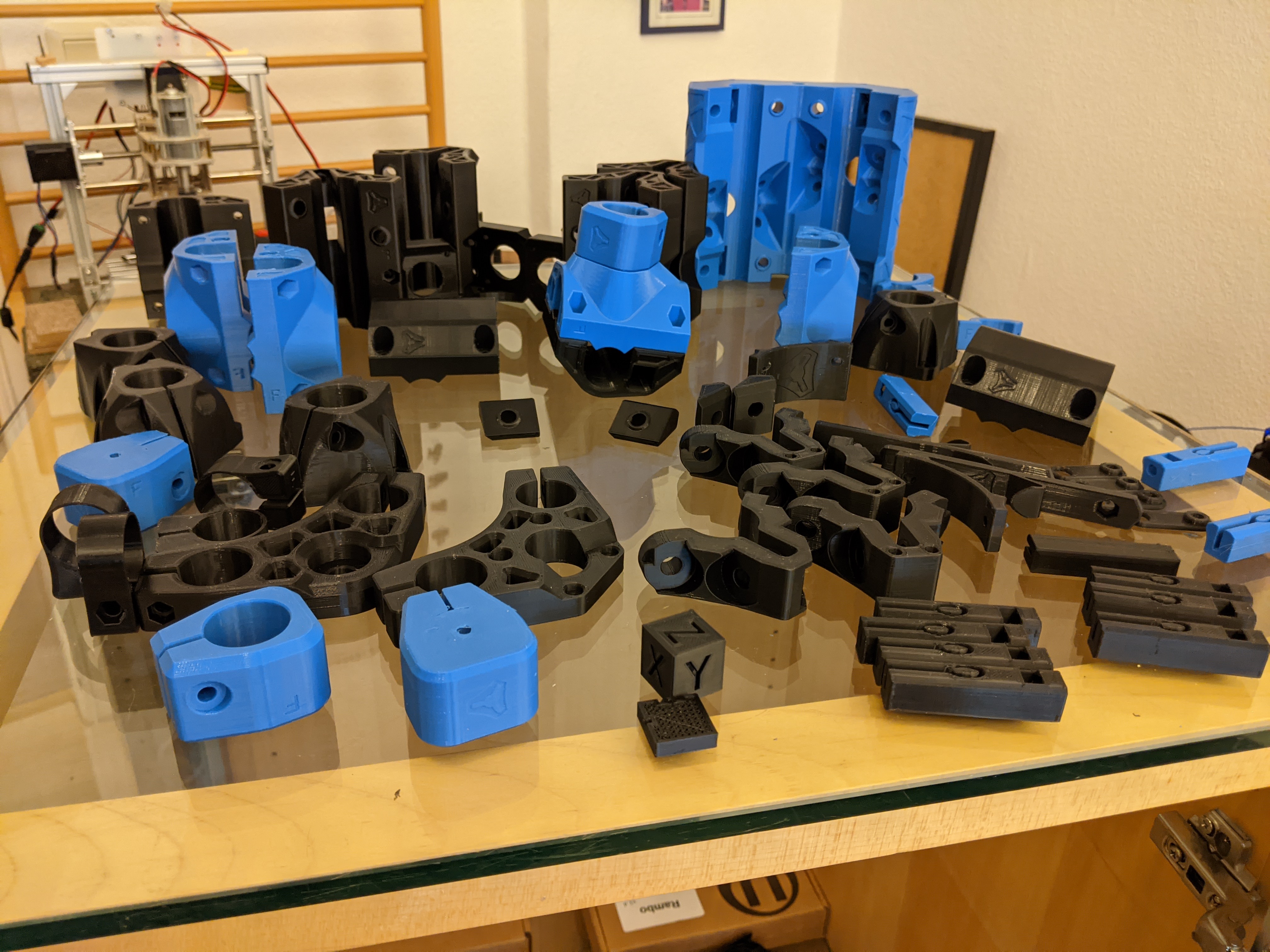
Tonight I will finish the last printed parts on my crowd-funded and seemingly error-prone Creality CR-6 SE (my first printer) that to my surprise did not burst into flames (yet) in the last two and a half weeks it was printing the whole set of Primo F parts night and day. I used rather conservative speeds after initial under-extrusion problems.
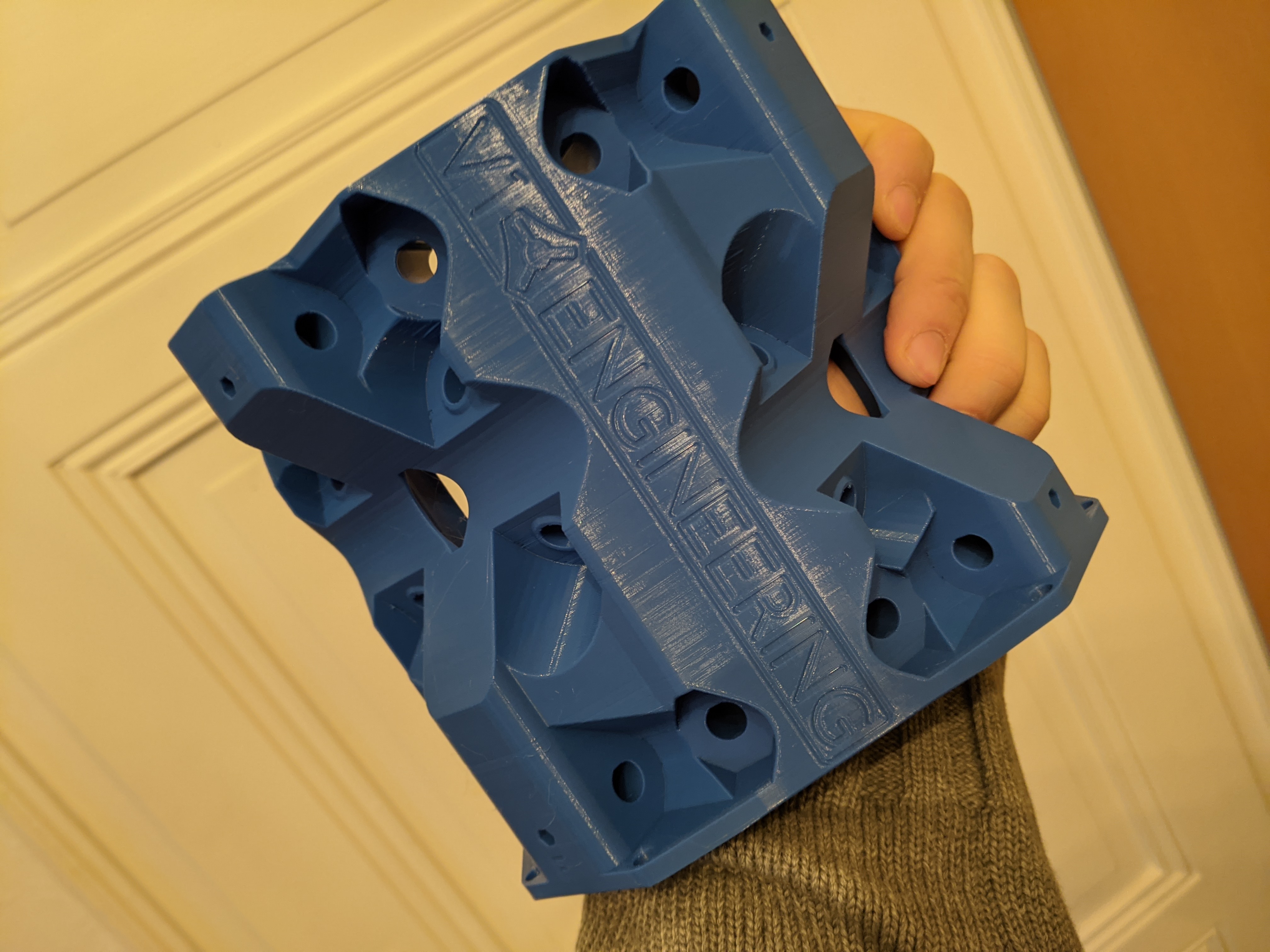
We lost some fine black PLA in the beginning, but when I presented the beautiful flawless core to my supportive wife yesterday evening, I knew all was going to be fine.
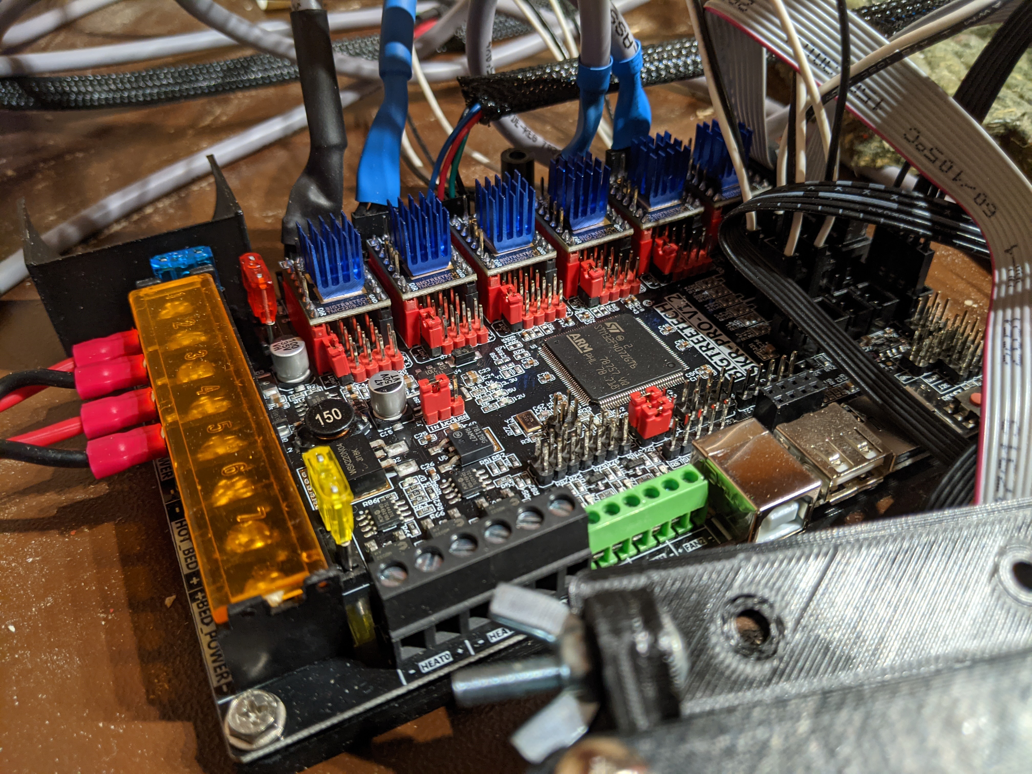
I will be using the official Kit and the RAMBo v1.4 board which I already received a few days ago. I am currently familiar with a grbl-controlled machine, but also open for marlin if i can use it with the CAM module in F360.
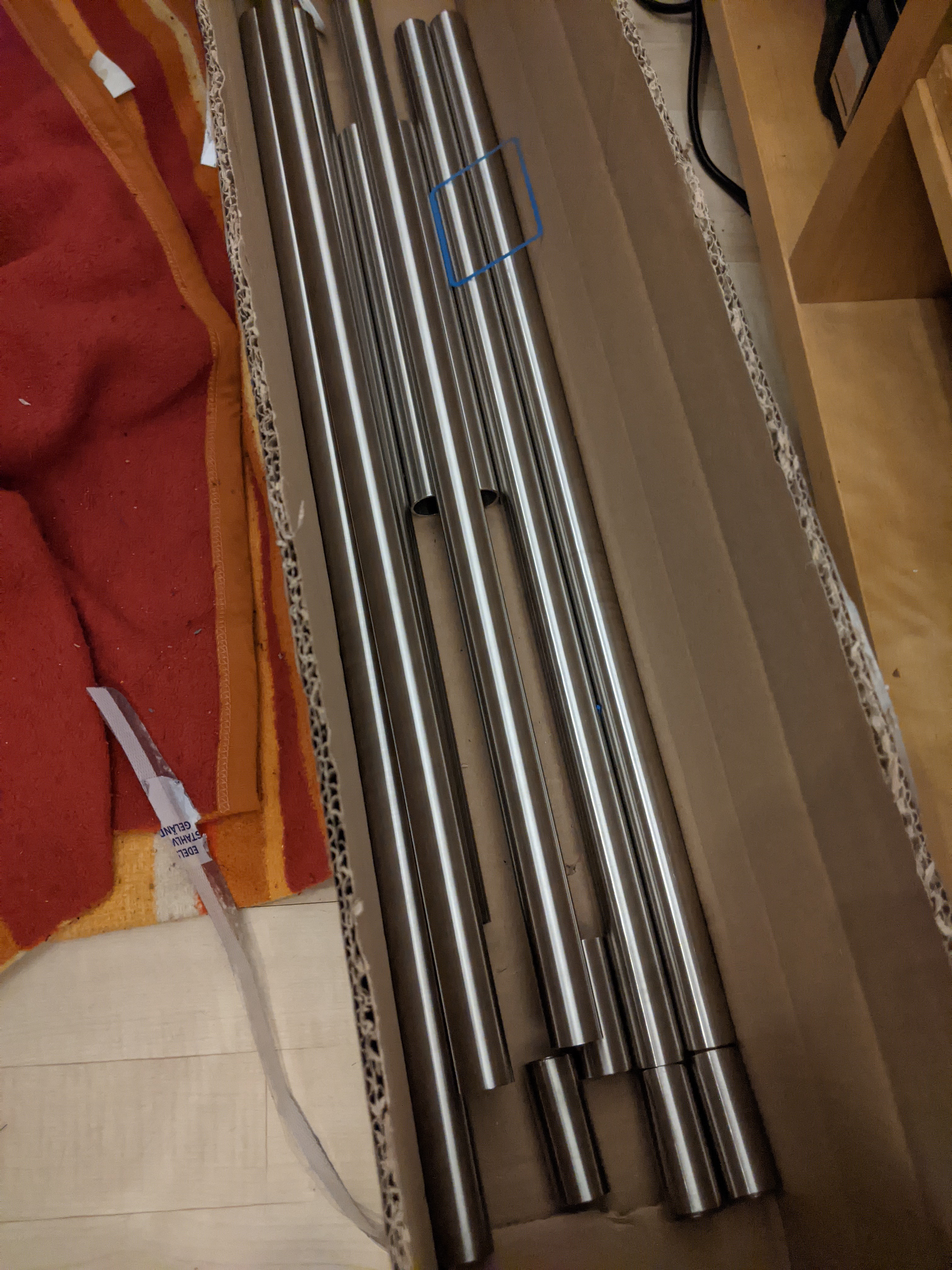
The 25mm stainless rails I bought ( locally online) should result in a workspace of 500x350x81 cm that I might expand later if needed.
Some tools are still on the way and will arrive this week.
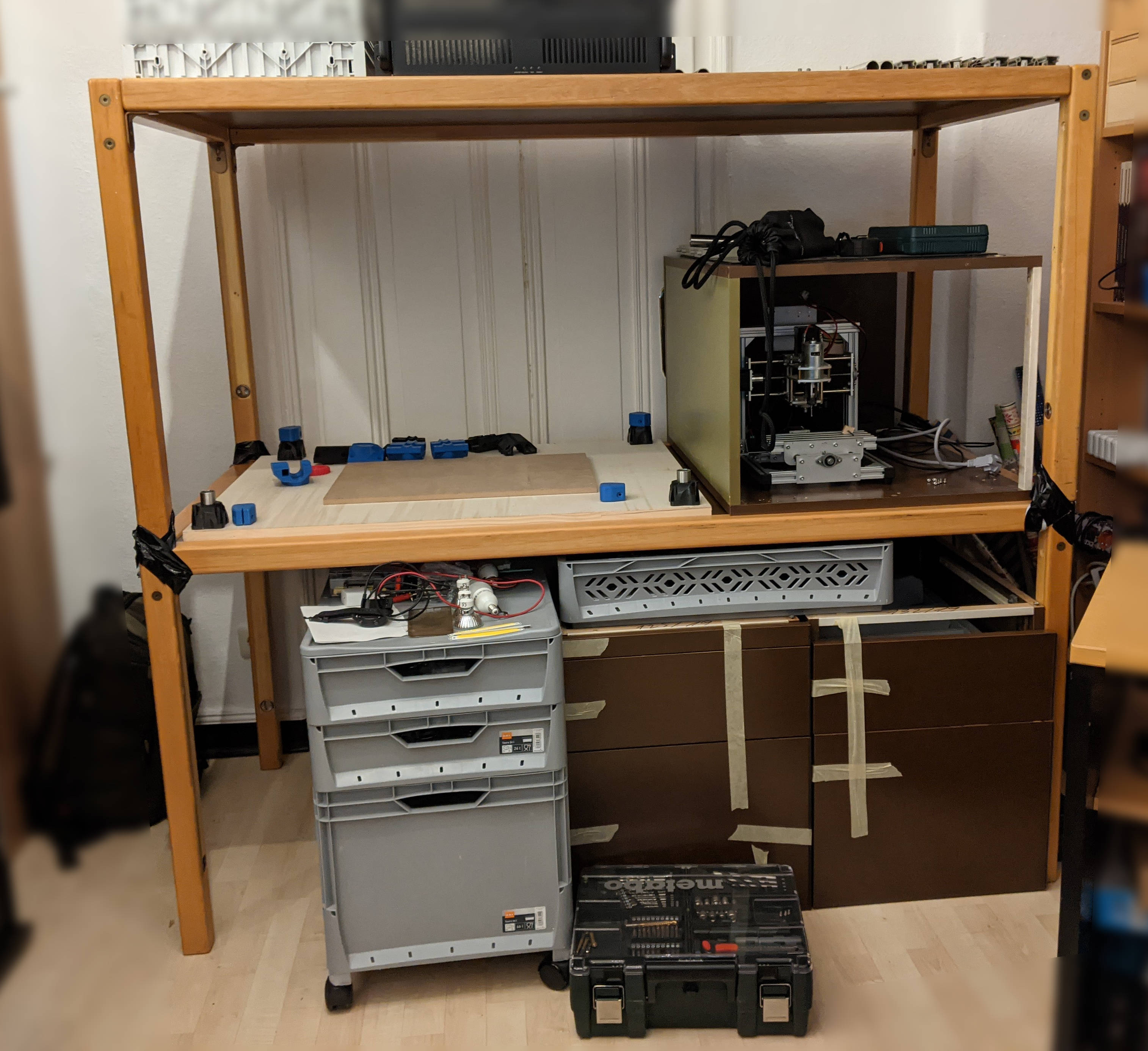
I have not yet decided on the table/base, but have some used 4040 aluminium profiles stored in the attic that I consider using to raise the z axis and make the assembly portable.
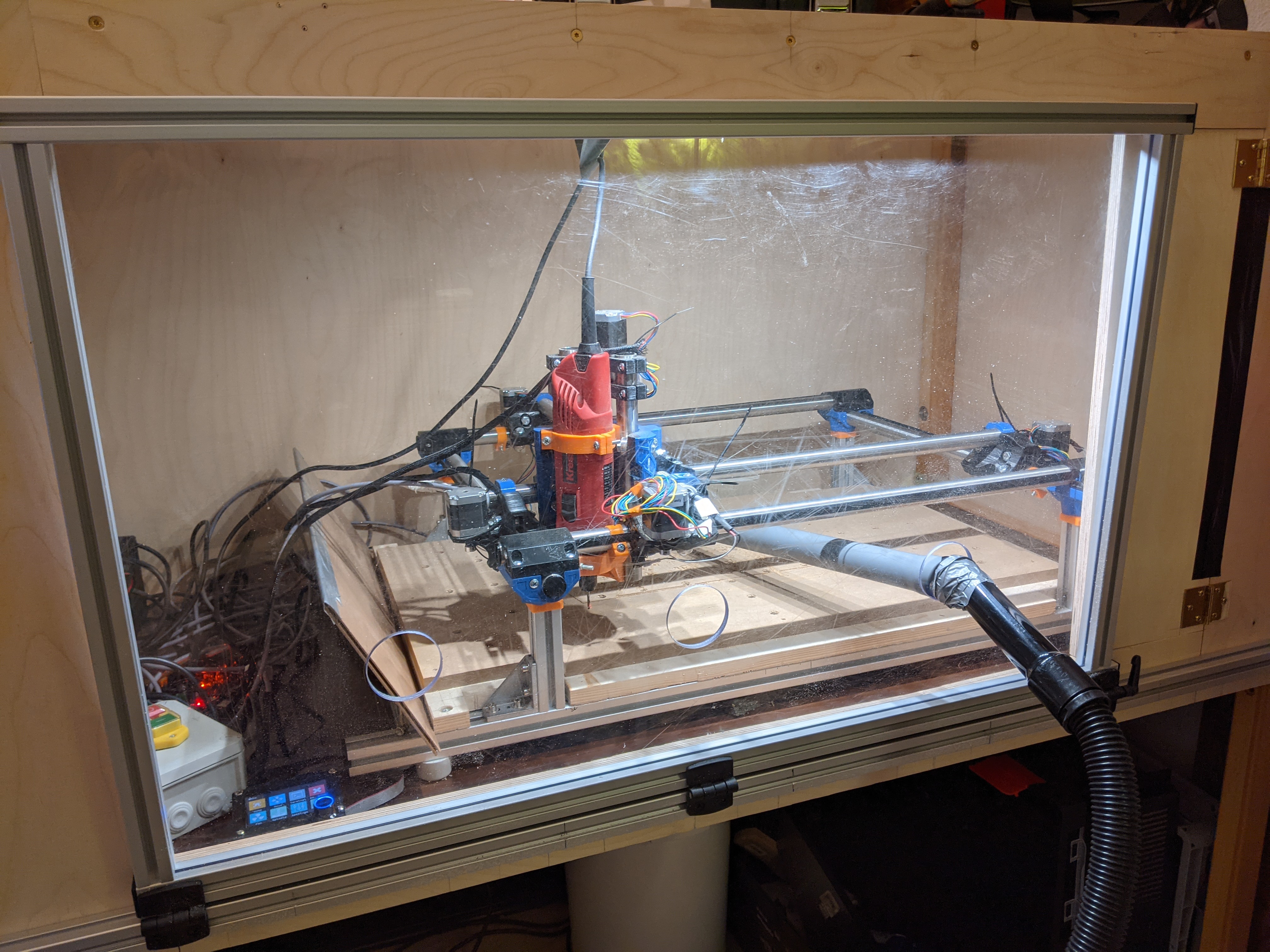
Two stacked wooden tables 160cmx80cm will be the frame of my enclosure. It really lacks stability at the moment but I will brace it with some matching wood. The duct tape joints in the picture are not a permanent fixture.
As you may have already spotted: I have to work with a " living room next door" man cave situation. I try to avoid the “2x4” look as long as possible.
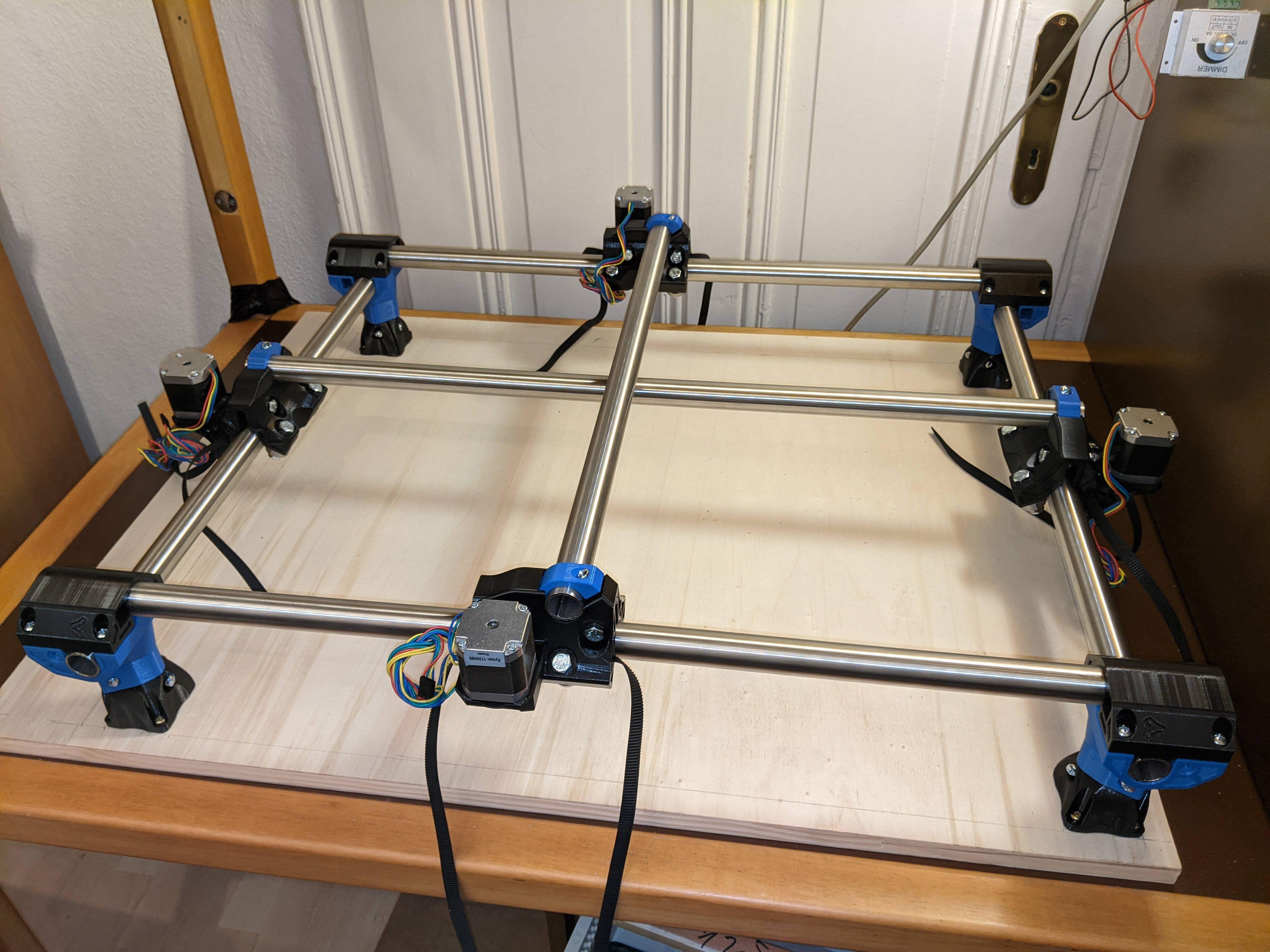
Last night I squared the base, assembled rails and trucks. The corners are also quite level as is.
My biggest concern right now is the length of the z-tubes (60mm) that completely disappear in the printed parts, while the pictures in the documentation has a tiny gap between feet and leg locks. I sanded them down a tiny bit but they are still reasonably close to 60mm. Is this an issue?
The M3x10 screws for the T8 leadscrew nut are not or only very lightly binding. I don’t think they would make any real resistance if a force pushes the nut upwards. Is this intentional or do I have a tolerance problem with my printed parts (holes)?
With the endstops I ran into a similar issues with the M2.5 screws that only really “screwed” into one of the mounting holes on each truck - the other one functions more as a registration pin.
It does not look too bad. Anything obvious I am missing?
Now I should give the RAMBo a proper enclosure, connect the endstops and feed everything through the tubes.
Honestly I forgot how loud steppers can be without Trinamic drivers. I will give it a try with the arduino + cnc shield with TMC2209s from my old mill as a comparison. Maybe the rambo 1.4 was not the best choice for me. SKR PRO?
When starting a new program I sometimes hear a single louder noise (like a snap). Does this indicate one or more of the bearings are too tight?
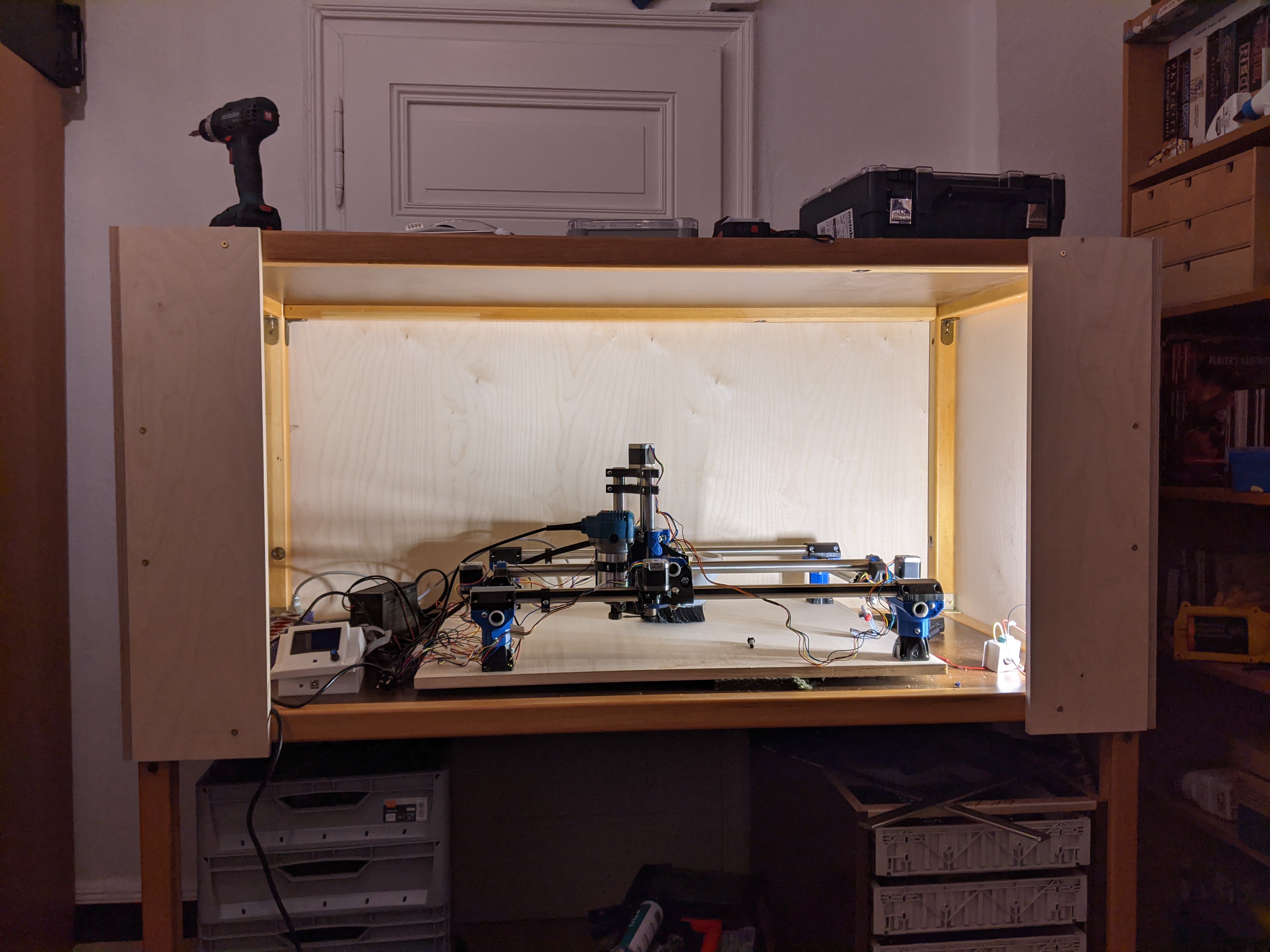
It took me way to long to build at least three walls around my enclosure and I am still searching for a cheap front door. Cable-managment is non-existent, because I can’t decide on the type of cables to redo everything for the endstops.
Although not an show-stopper for me, the costs of the stuff around the CNC add up quickly if you can’t just toss it in a dedicated workshop. I love to improvise, but the windowed door and the best choice for the final cable tree is still giving me a headache.
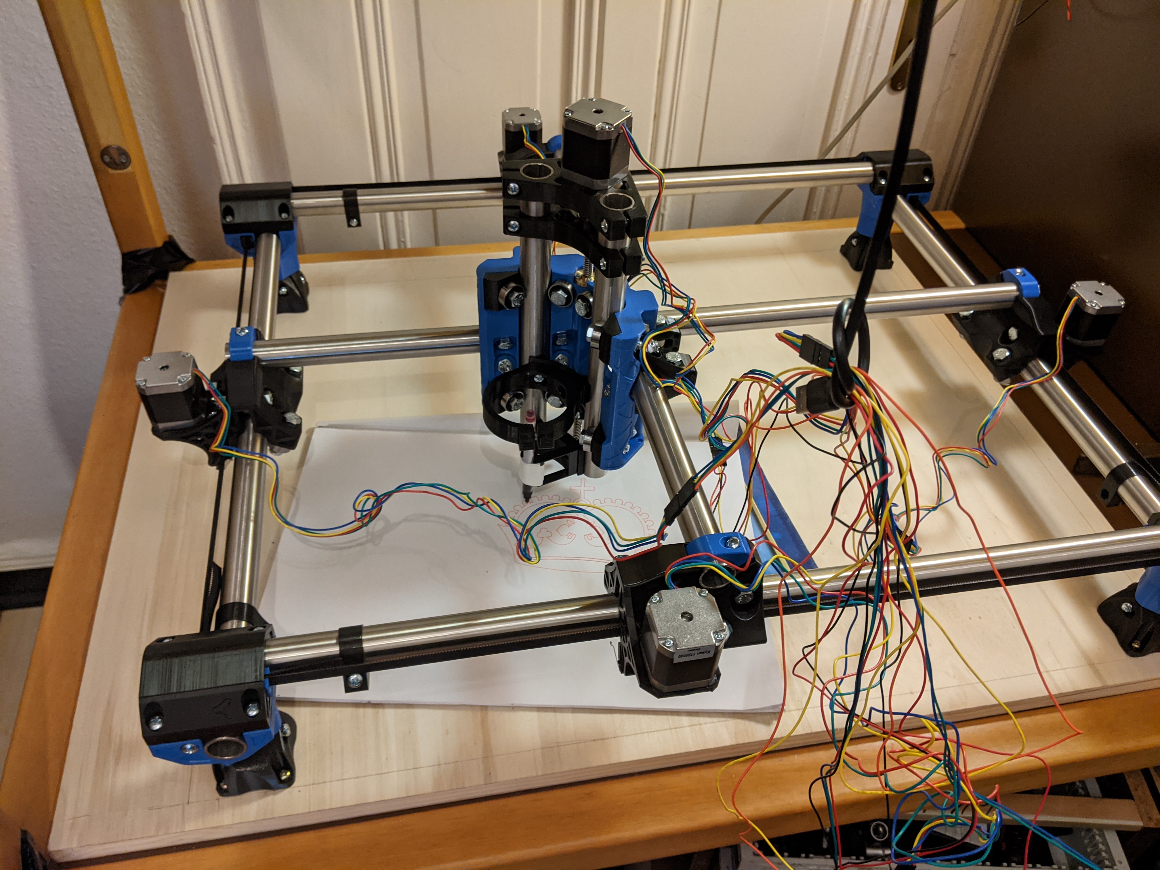
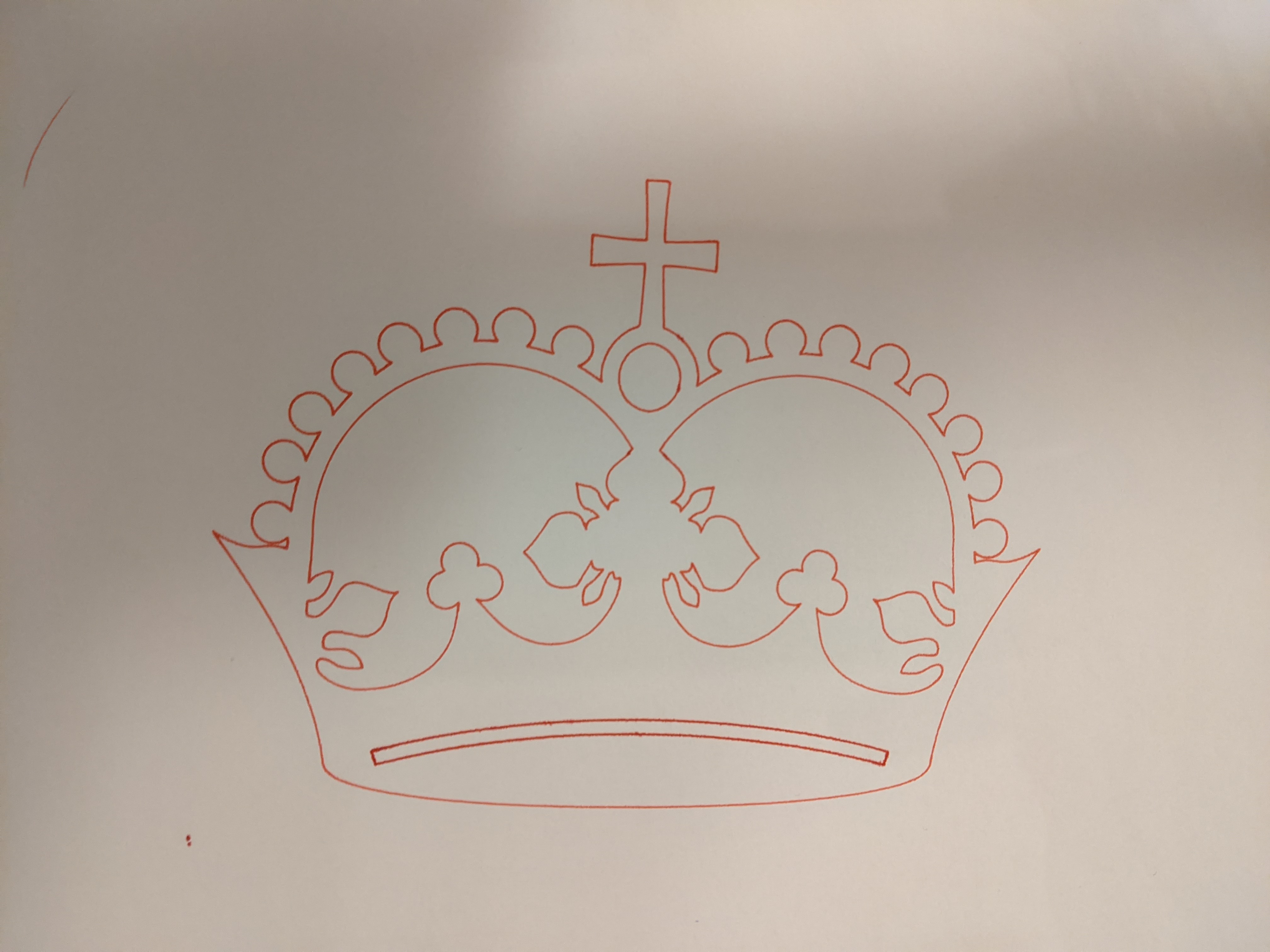
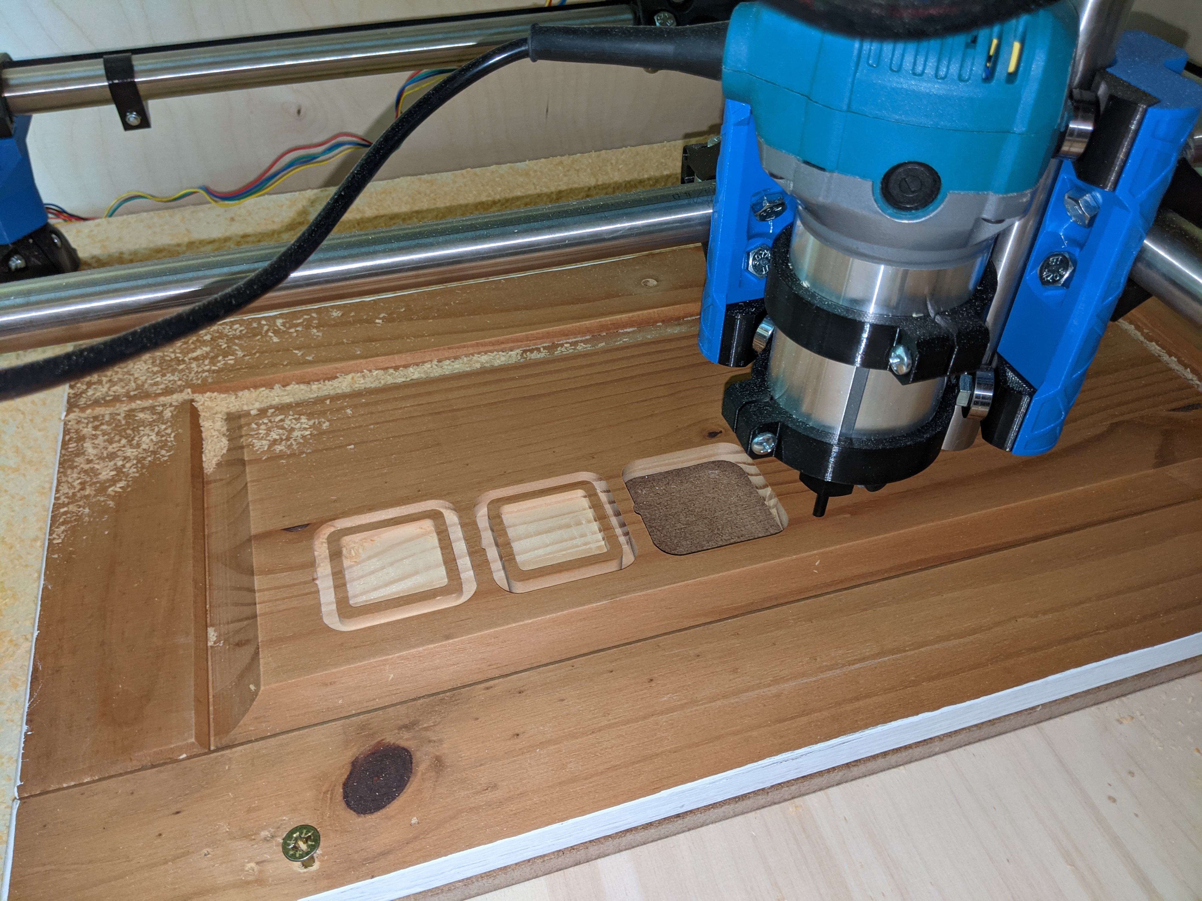
Nevertheless I cut my first simple part thrown together in Fusion 360+CAM and had my moment of pure happiness.
I bought an angled ball point milling bit of a total length of 100mm that is way too long for my current height
I printed and assembled a dust shoe but later discovered that it just wont fit if I want to preserve my working area (still looking for better solutions than just manually vacuum the path of the tool.
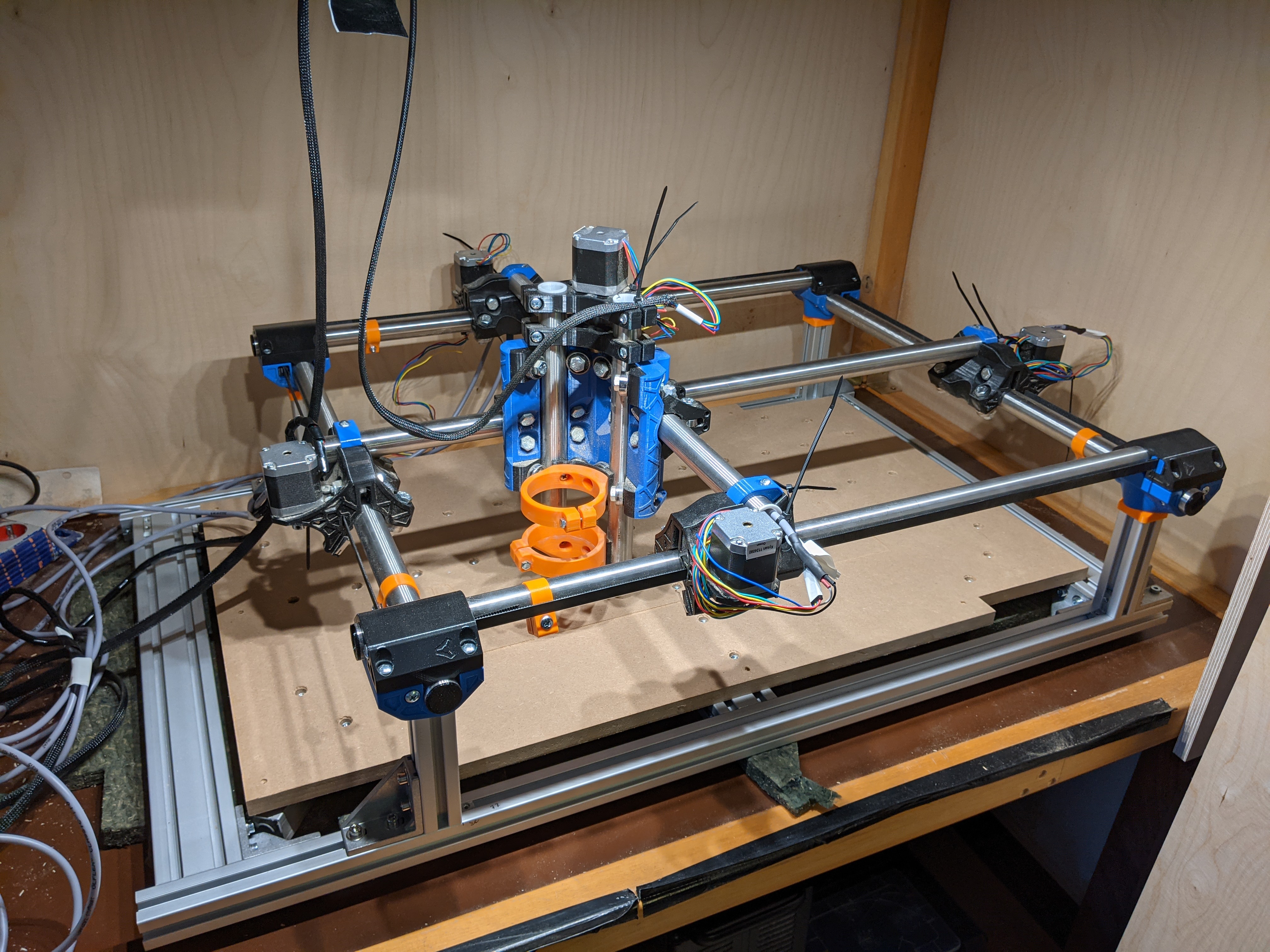
During lockdown I drilled my first wasteboard and milled some parts. The incomplete enclosure was (and still is) a huge problem, so I bought aluminium extrusion to build a door (ongoing) and also decided to rebuild the mpcnc on a aluminium frame.
Last weekend I finally flashed the dual driver firmware for my rambo 1.4 and threaded the new wiring harness (now including the four endstops) through the tubes, while all cables on the z-axis are still dangling from the ceiling.
Now I have to redo by wasteboard and re-tighten the core that has become quite loose in the last months of use. I hope there is no material fatigue in the PLA Parts.
I’d suggest buying a nice new one for daily use and retire your current tape for the tape measure trick. I tried to use the “cheapie” tapes from Harbor Freight and they didn’t support my cables adequately - but then I’m using 6-conductor shielded cables on all my axes with 2 going to Z for RPM control on the router.
That is impressive and I will have a look at my local hardware store for a wide tape. Now that I work with the new cable harness, working with the PET sleeves should be much easier.
I raised the z-axis a bit from the recommended height while mounting everything on the new frame and now have 25mm clearance from the wasteboard with this milling bit.
Shortening the shank could give me another 8mm without the collet clamping in the coated (hardened) area. But I do not own tools to cut hardened steel atm.
One step towards completion and two steps in the other direction.
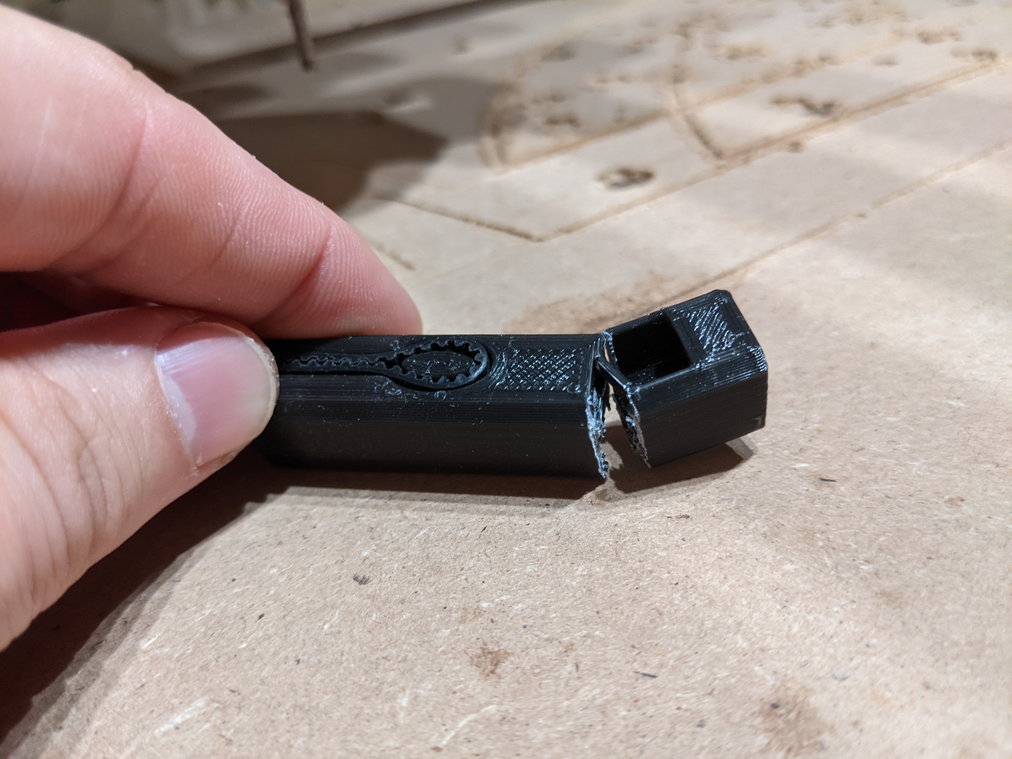
Yesterday I broke at-least one belt tensioner, while milling and am currently reprinting all of them using an “enhanced” PLA. After the dual-endstop conversion there was a problem with slipping belts and I must have overdone it for the Y-belts. Bummer.
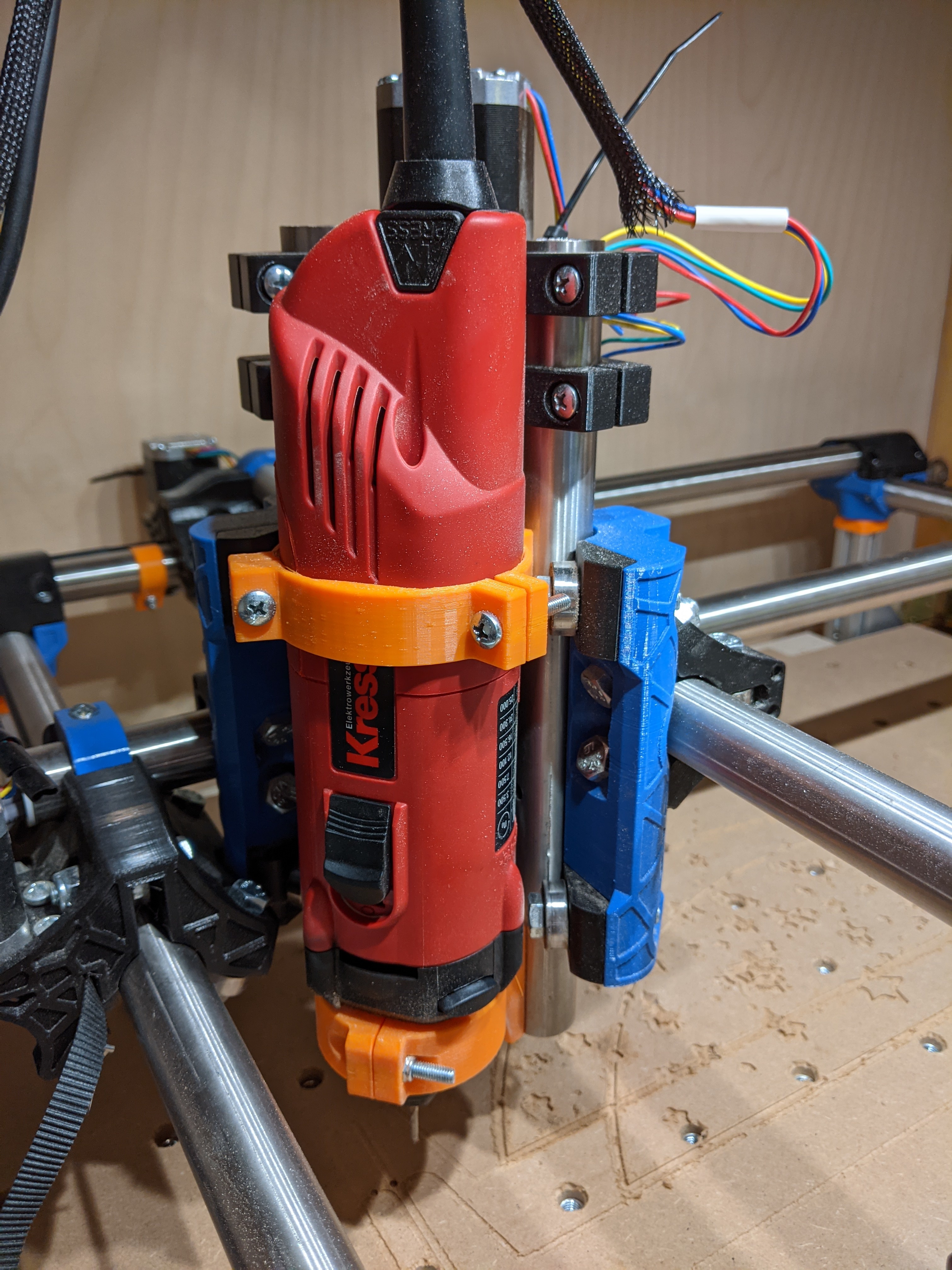
I also upgraded the motor to a Kress 1050 FME-I (ebay steal) because of the better selection of collets it came with (finally native 1/8" for small stuff!) and the noise profile.
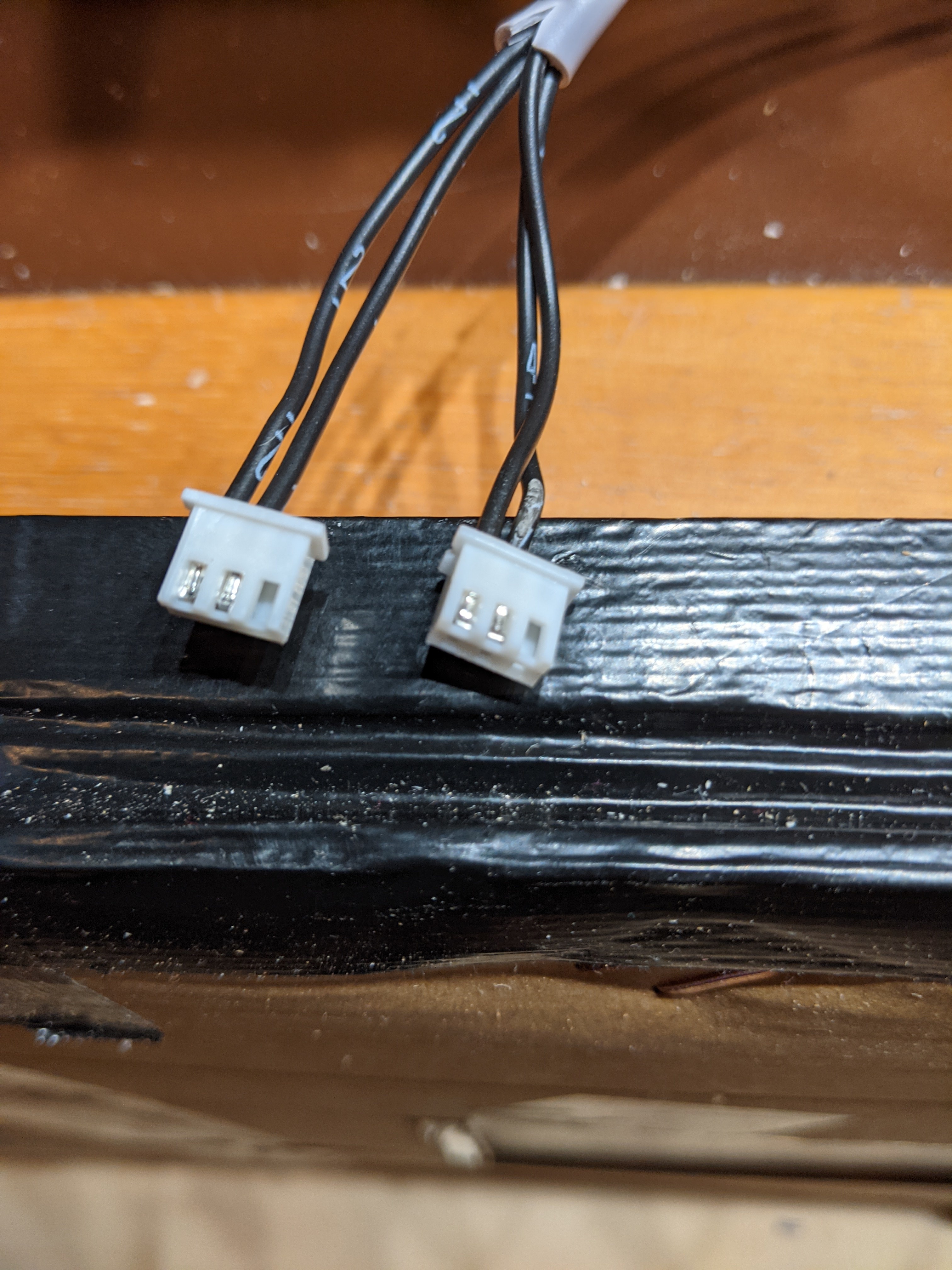
Last night I swapped the RAMBo 1.4 for an SKR pro with the recommended TFT35. While I am very happy with the cooler steppers and the touch user-interface, I think the combination of the stripped JST endstop sockets and the molex connectors from the original kit is too sketchy to just drown everything in hot-glue. The JST crimp kit is sitting next to me and now I have to gather all my the strength for another evening with wine, tears and crooked metal pieces all over the place.
Inserting the crimped wires into the JST-XH connector is way easier than molex which I did before. After the endstops, the TFT connector was next. I am actually glad I can now redo the stepper cables as well.
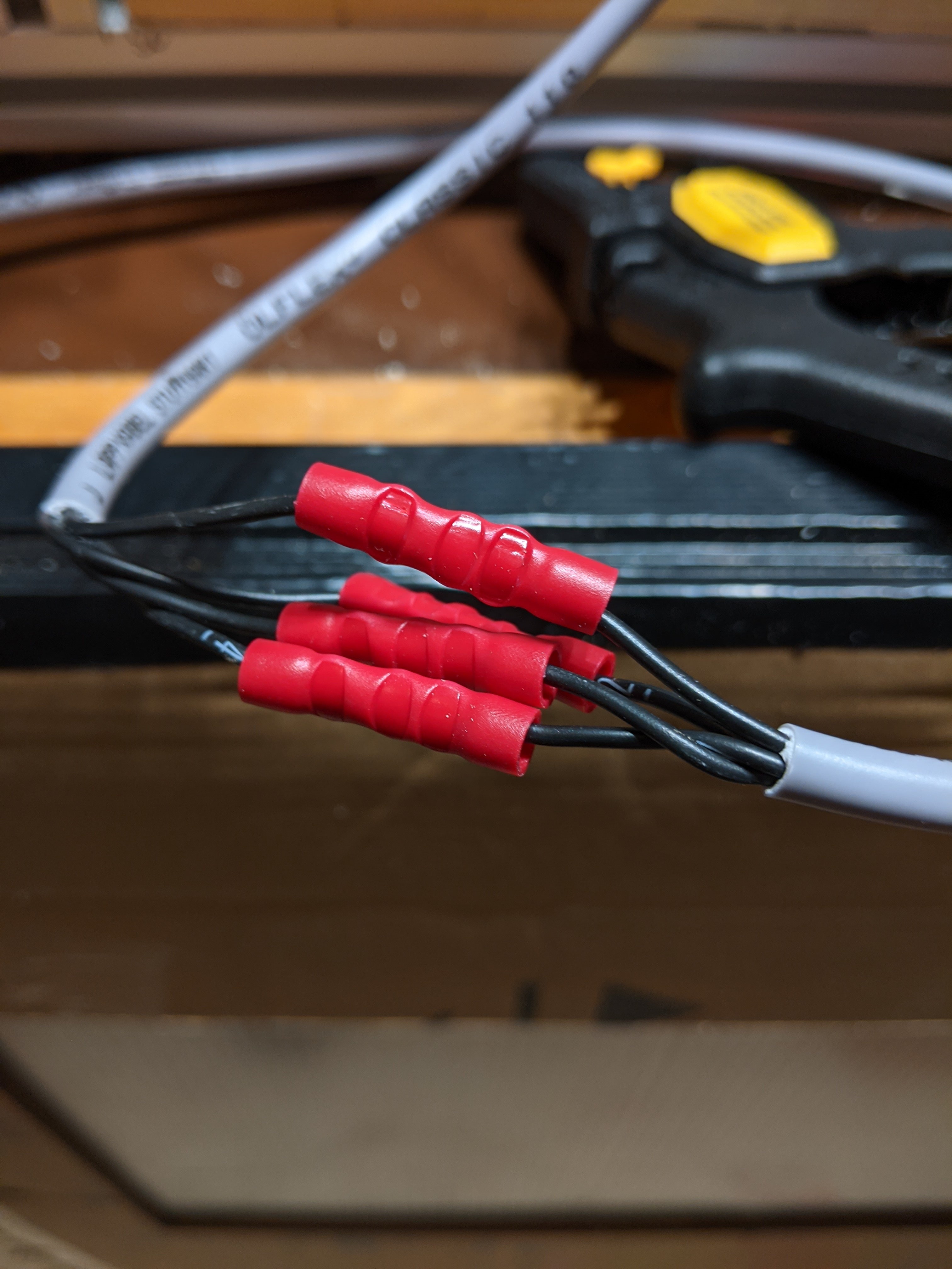
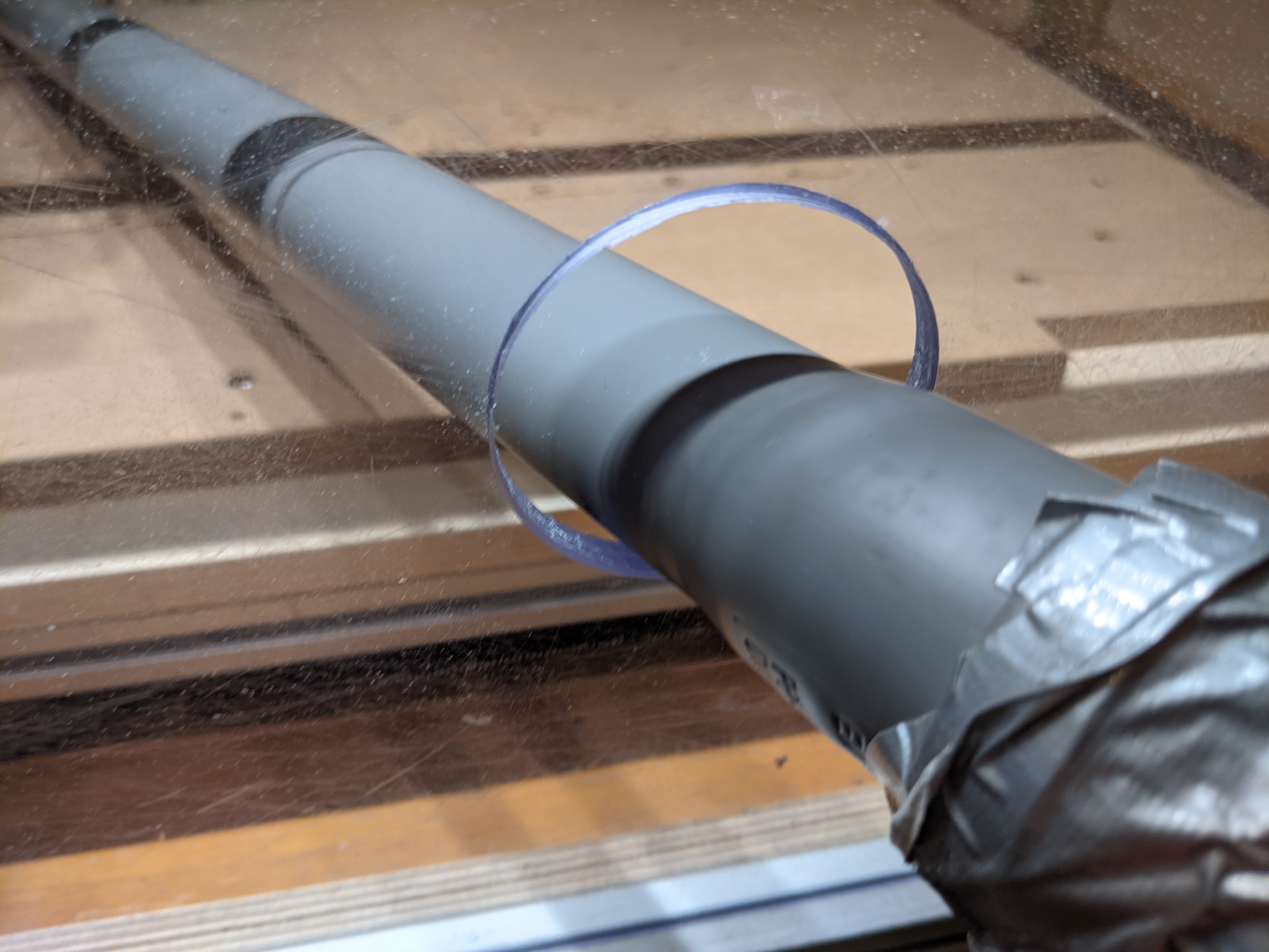
This time I extended the existing cables with the “crimp tubes” in the second image. Not 100% sure if this is the intended usage, but it seems to protect the two twisted ends quite well. Previously I soldered and isolated these connections with heat-shrink tubing.
Regarding the tape measure method: I saw the prices of the better ones in my local hardware store, and bought three cable chains oversea - 1 meter each. But this is something for another day.
The goal is to manual vacuum while watching the machine do its thing. Hopefully the dust buildup on the acrylic panel is manageable, the negative pressure keeps everything inside and the air flow removes enough heat from the enclosure.