Hi Jeff,
Thanks for the reply.
I’m using one of these to take a feed from the 48v PSU and convert down to 12v/10amp. Is that ok?
Or should I just power the SKR power and SKR steppers from the laptop style 12v/6amp PSU?
(Does the board power and stepper power just get bridged from the same supply?)
Technically, it should be fine. There were reports (not by me) that the spindle power supplies have a lot of noise. They claim 96% efficiency, so I would assume it is a buck converter and it will use about 2.5A (probably a bit more at max, but you won’t need all 10A either) from your 48V PSU. I don’t think you mentioned if the 48V PSU has enough current capacity for the spindle and the 12V supply.
I think I may end up using the 12V/6A power supply (as listed in the V1 store), and just send that to the board, bridging it to the stepper power on the board too.
It was just a bit concerning when I say the gauge of the wires in the SKR box, and then the gauge of the wires from the laptop style PSU. Probably just overthinking it!
I’ll do some testing with the trusty multimeter and calculator later and see whats best.
Would be nice to have it all together as one system though.
My next task is working out the best way to connect the spindle to the SKR board to control it’s power and speed.
I have a WS55-200 driver for the spindle, so I’m hoping I should just be able to send PWM from the SKR directly to the inputs on the driver. Trying to comprehend the manuals is…challenging to say the least
Wobble:
So, I simple disassembled the core and reassembled it. A little bit tighter than before on the bolts, but the bearings can still move freely with one finger and thumb. Only now, the whole thing doesn’t wobble anymore. It’s pretty solid. Phew.
X-Axis:
I don’t know if it’s just simply because of the length of the X-axis (870mm), but I can’t get good rigidity between X1 and X2. When you move one of them on their own, it moves on its own for about 10mm before the other starts to move too. However, when the core is moved, all axis move together in perfect synchronicity. They are all square and when I settle all the axis by moving the core into the rough middle, there is the exact same distance from the corner to each truck. So, I’m not sure whether to leave it as is, and hope the dual motor running dual end stop will help with this, or to try fiddling with it more.
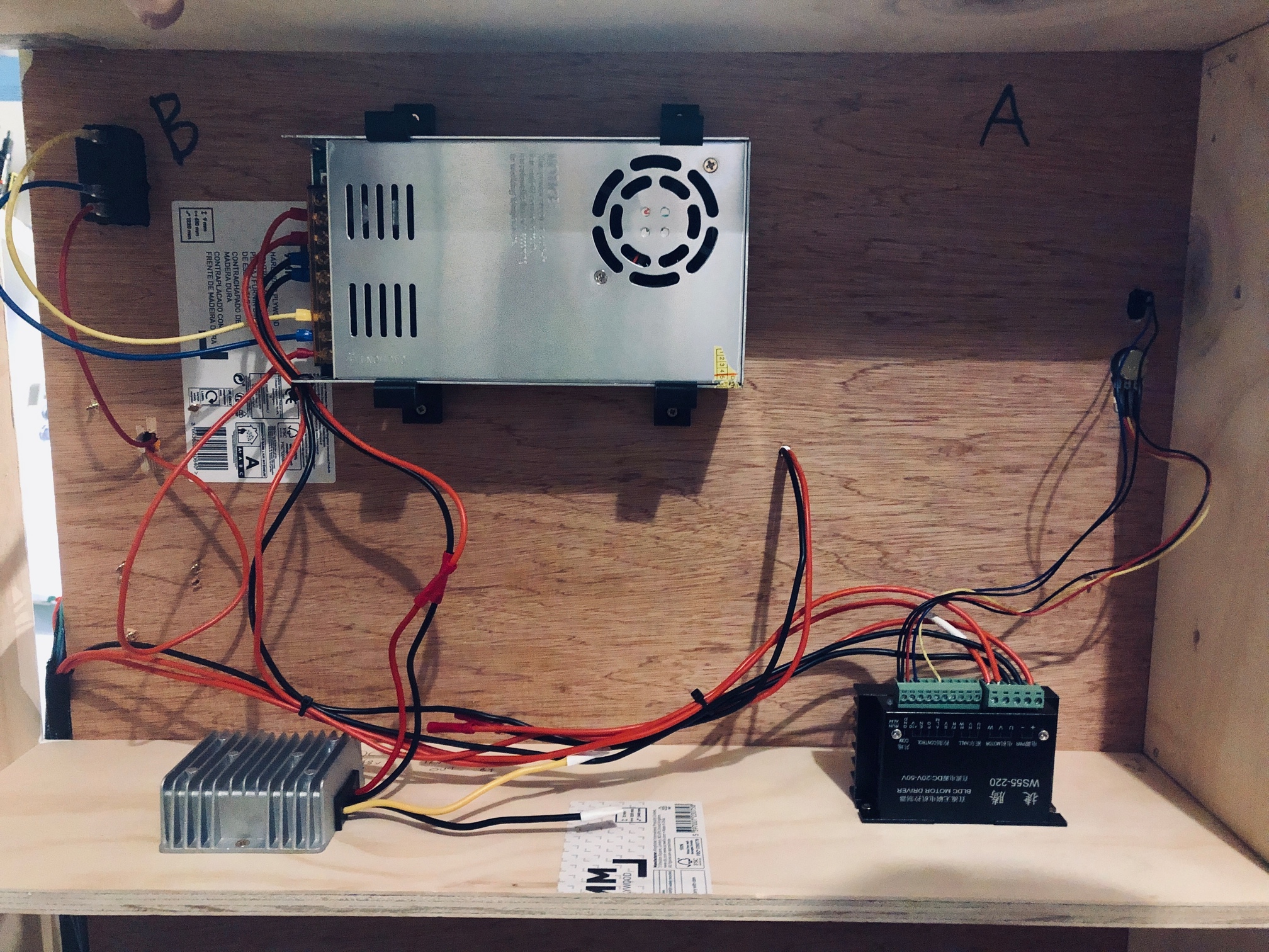
Power: (With some help from someone else with calculations)
I have a 48V 12.5A PSU for the spindle.
The spindle is 500W, so its max draw is going to be around 10.5A.
My steppers - all 5 will draw around 1A.
Assuming steppers running at 3/4 power with 2 phase coils:
Per motor - 2 × (2×0.75)^2 × 1.4 = 6.3W
5 motors = 32W
Inefficiency taken into account, allow 40W.
40W at 12V = ~1A
The SKR PRO V1.2 will be a few mA.
…So, technically I can power it all from the PSU (with my 48v -> 12v 10A converter).
Now I at least know I’m not going to be doing anything dangerous power wise, I will try this out and do some solid tests with a meter once everything is set up.
If I start seeing it’s too much to handle in some tests, well, then I have the 12V 6A laptop style PSU to fall back on.
Moving forward:
Finish last parts of wiring.
Extending spindle power cables
Soldering all stepper and end stop switch wiring to D-Sub plugs
Soldering internal D-Sub connections, ready for the main board
Flashing the main board and starting to connect up all the wiring.
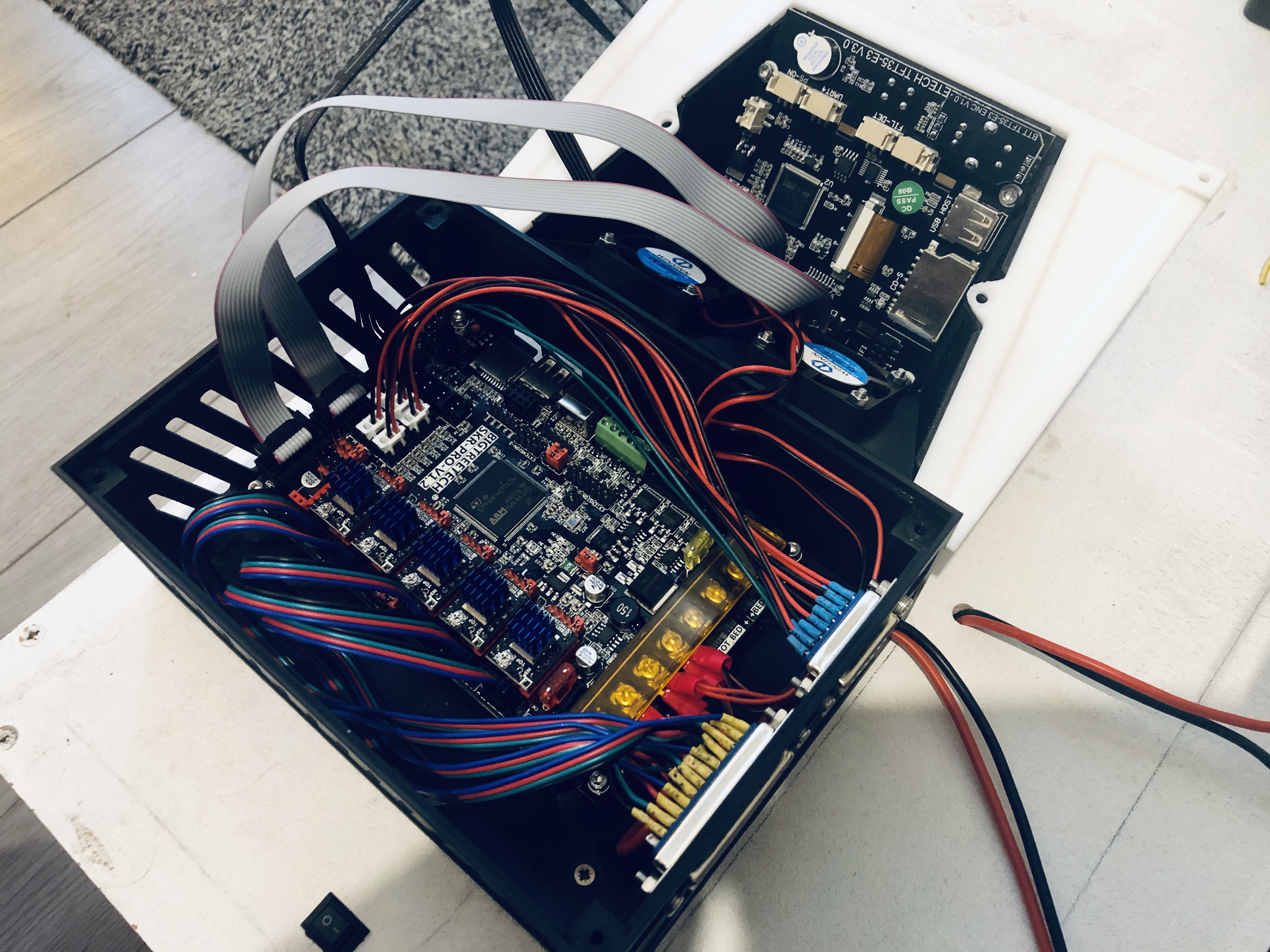
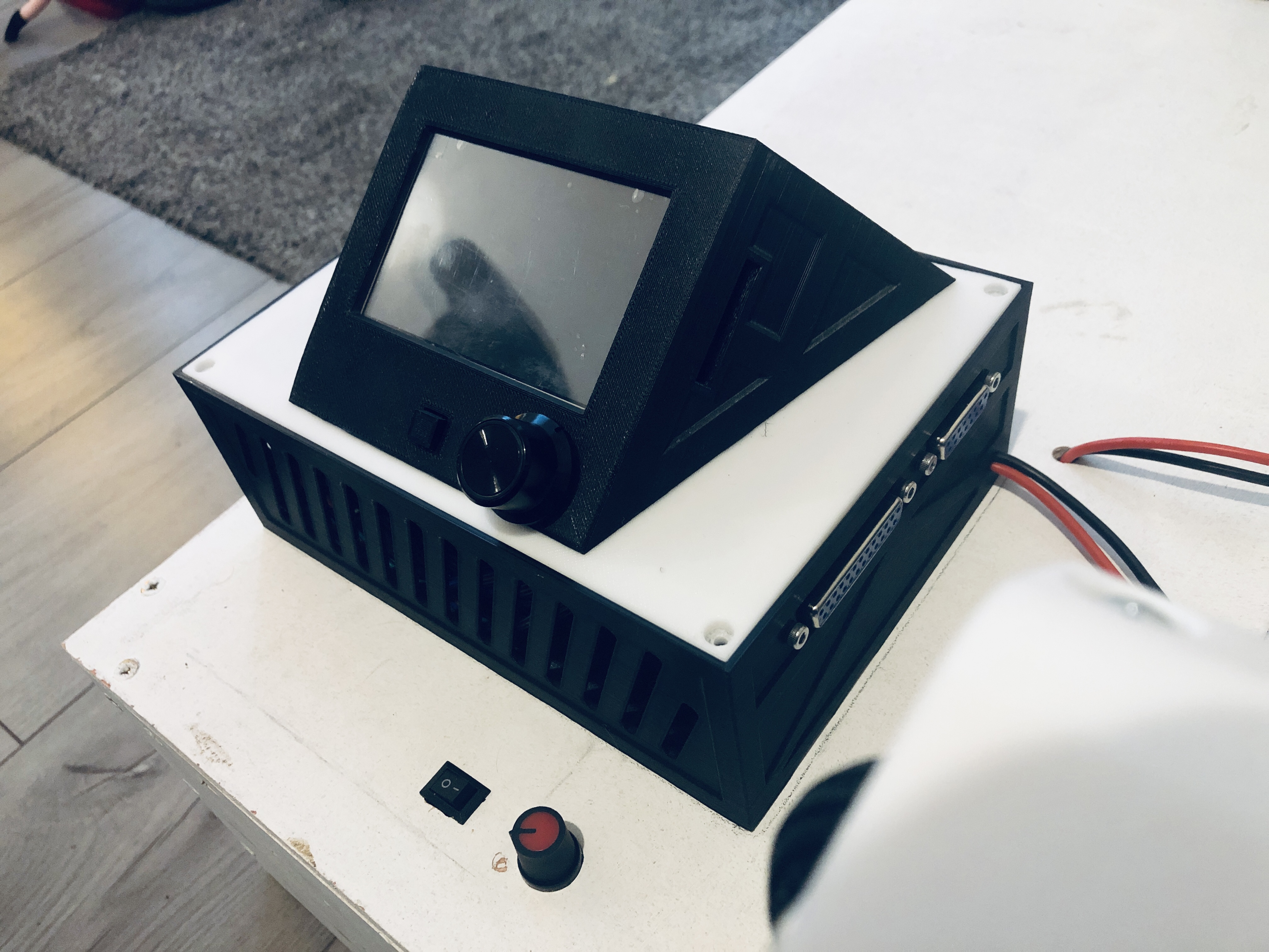
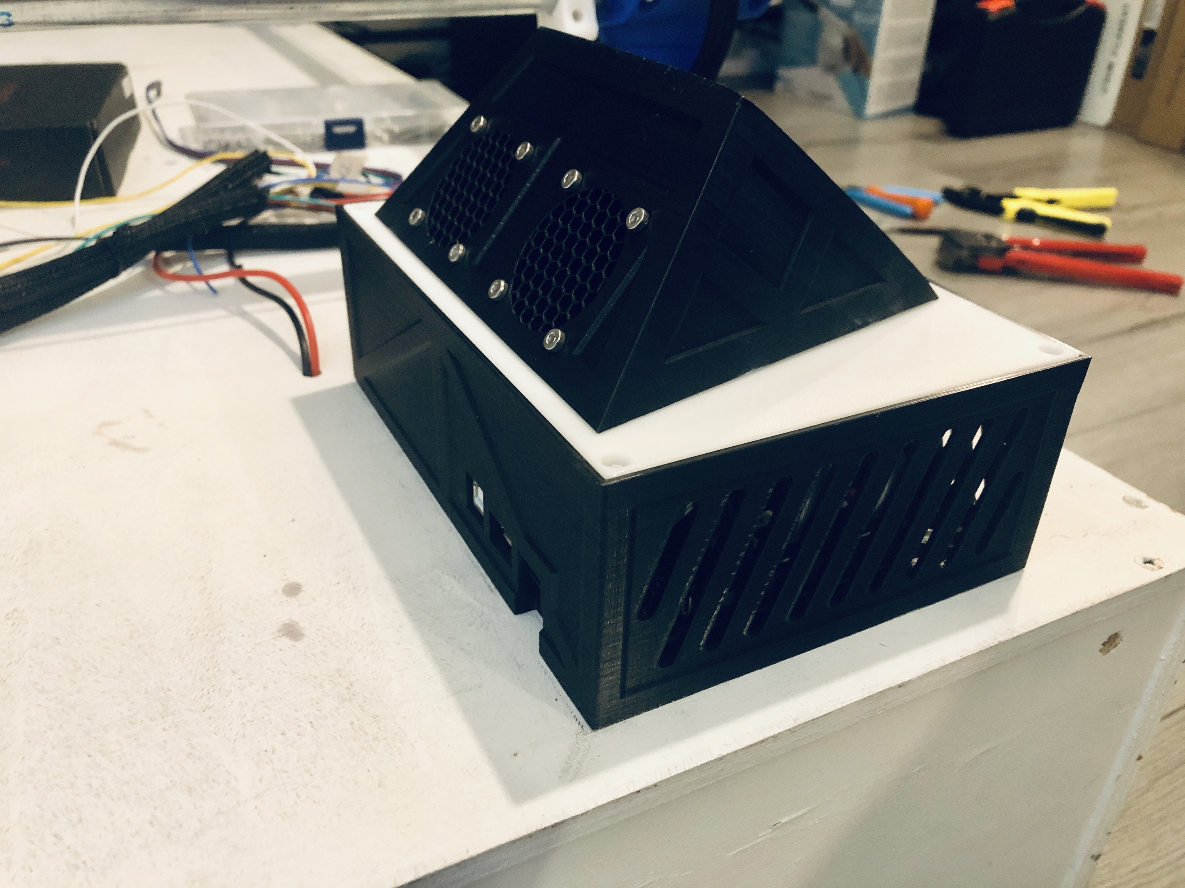
I have finished printing my case for the main board, and also some protective covers and mounts for the PSU. I'm going to wire things up on the bench, run some tests (as mentioned above) and test the power draw of all components. Then I'll know which power 'option' I will be taking.
Final position and connection of everything onto table top and connections
Tests and then...Crown!
I’ll post some pictures of progress later tonight hopefully!
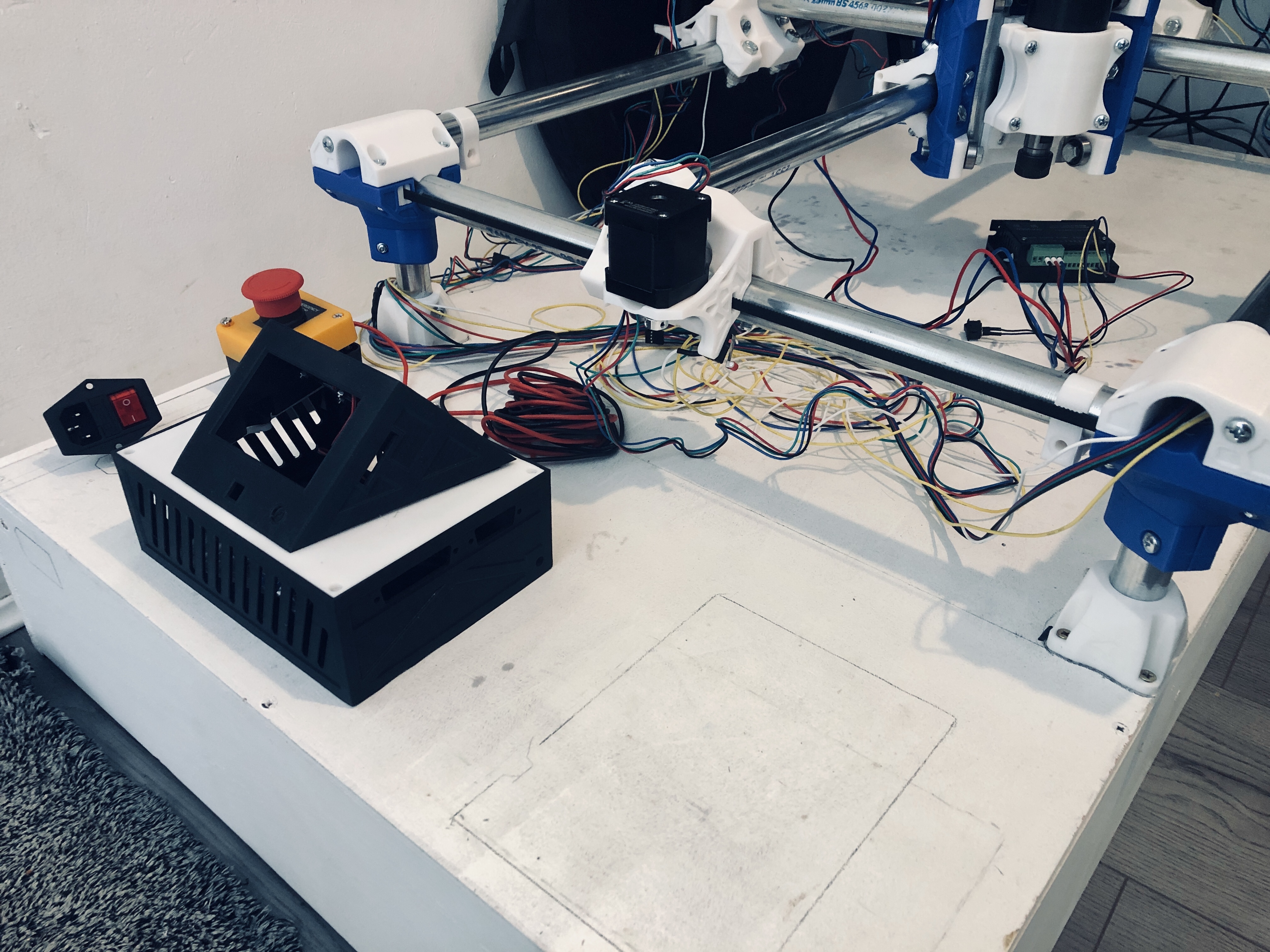
I decided that I had to mount the control box so the rear of it didn’t face the workspace. This was because the fans are on the back, and I was concerned about dust and particles from the workspace being ingested during jobs.
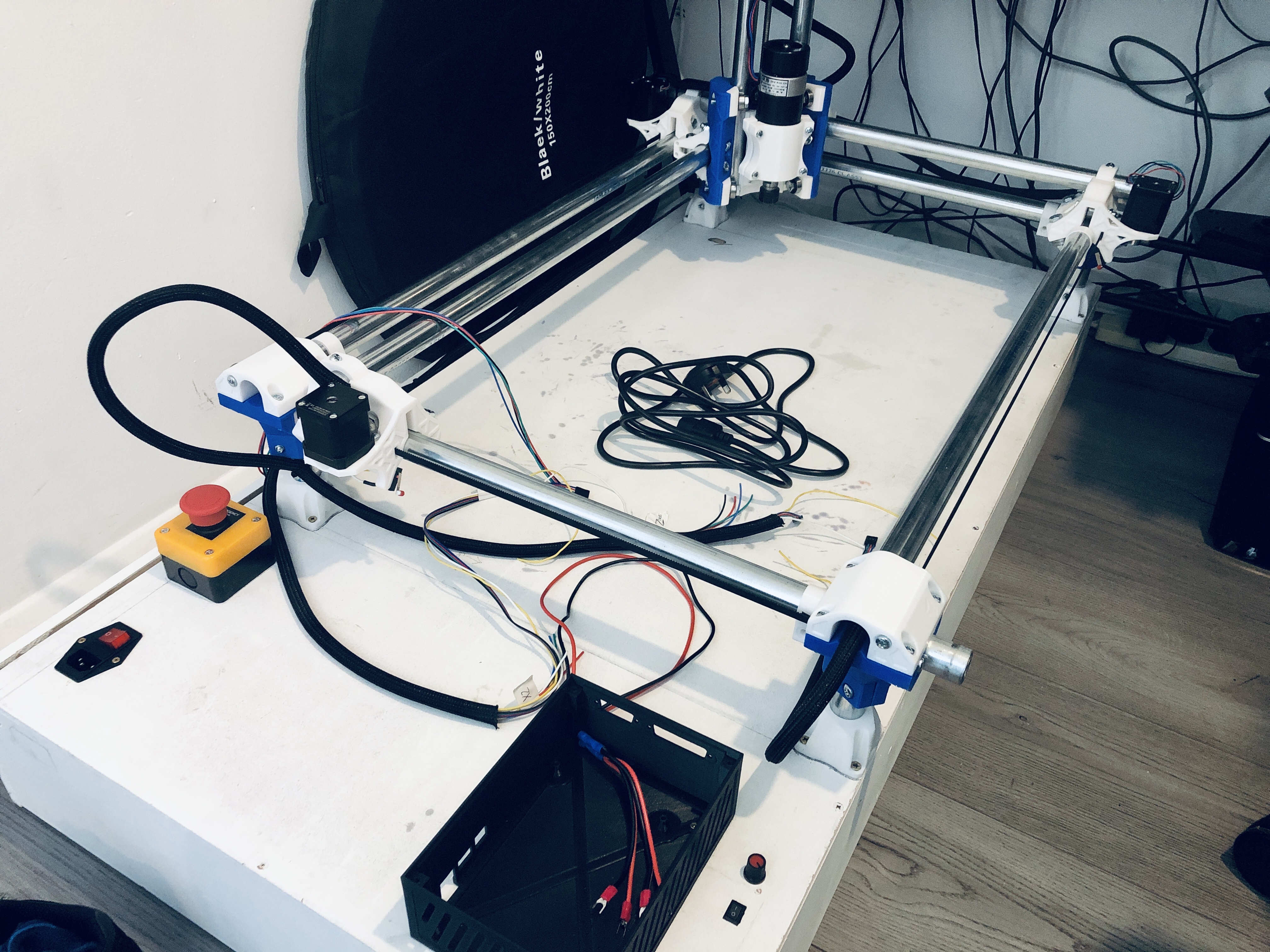
So, I settled on the final positioning of everything. I drilled and mounted the emergency stop, master power switch/input and the spindle power/speed controls. Then I wrapped all the cabling in split sleeving, and finally screwed down the control box to its final position.
With that done, I finally mounted all the power supply components on the underside.
Wiring still needs to be tidied, and I’ve still yet to connect up the 12V supply to the board, but everything is in place.
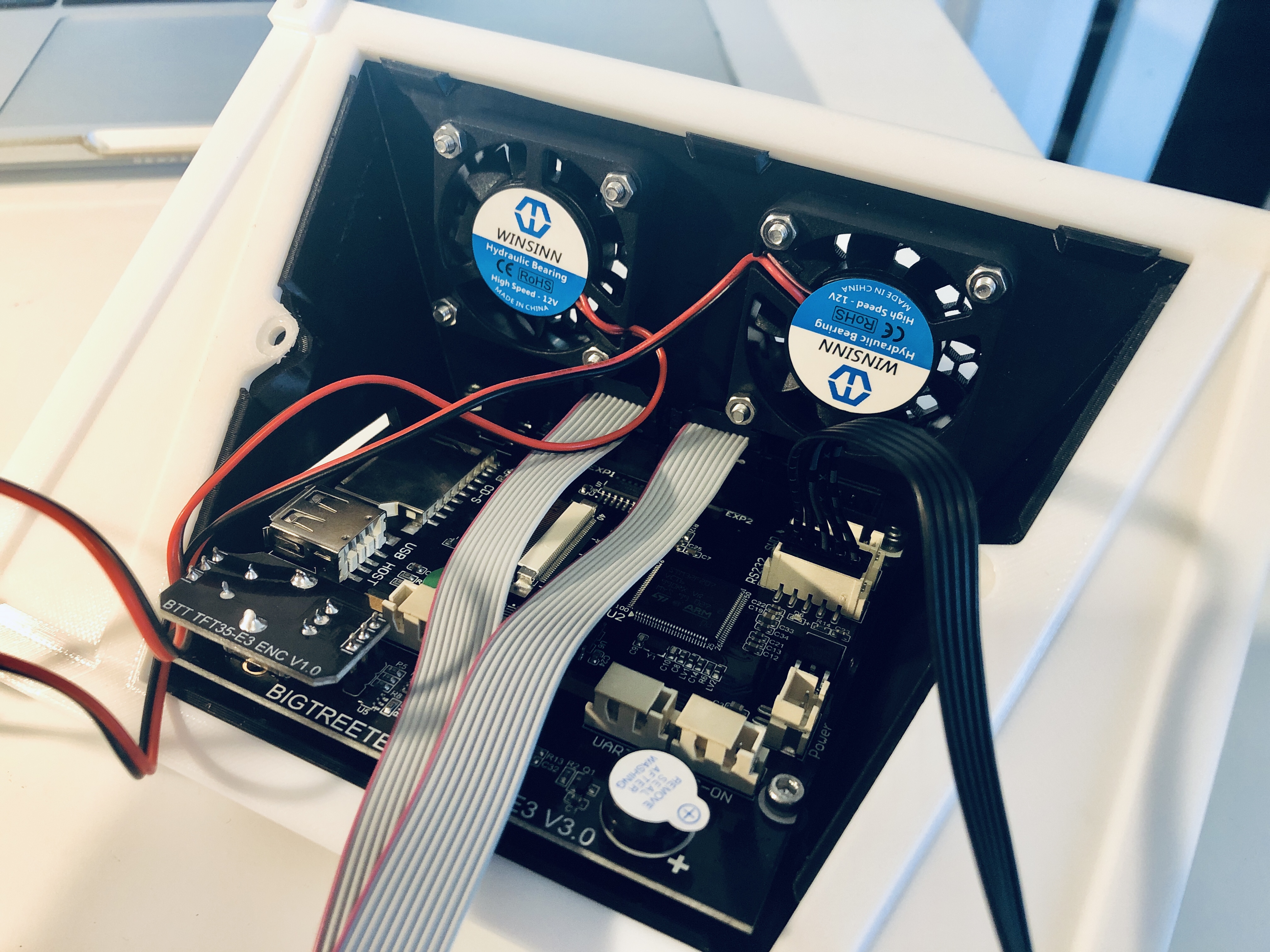
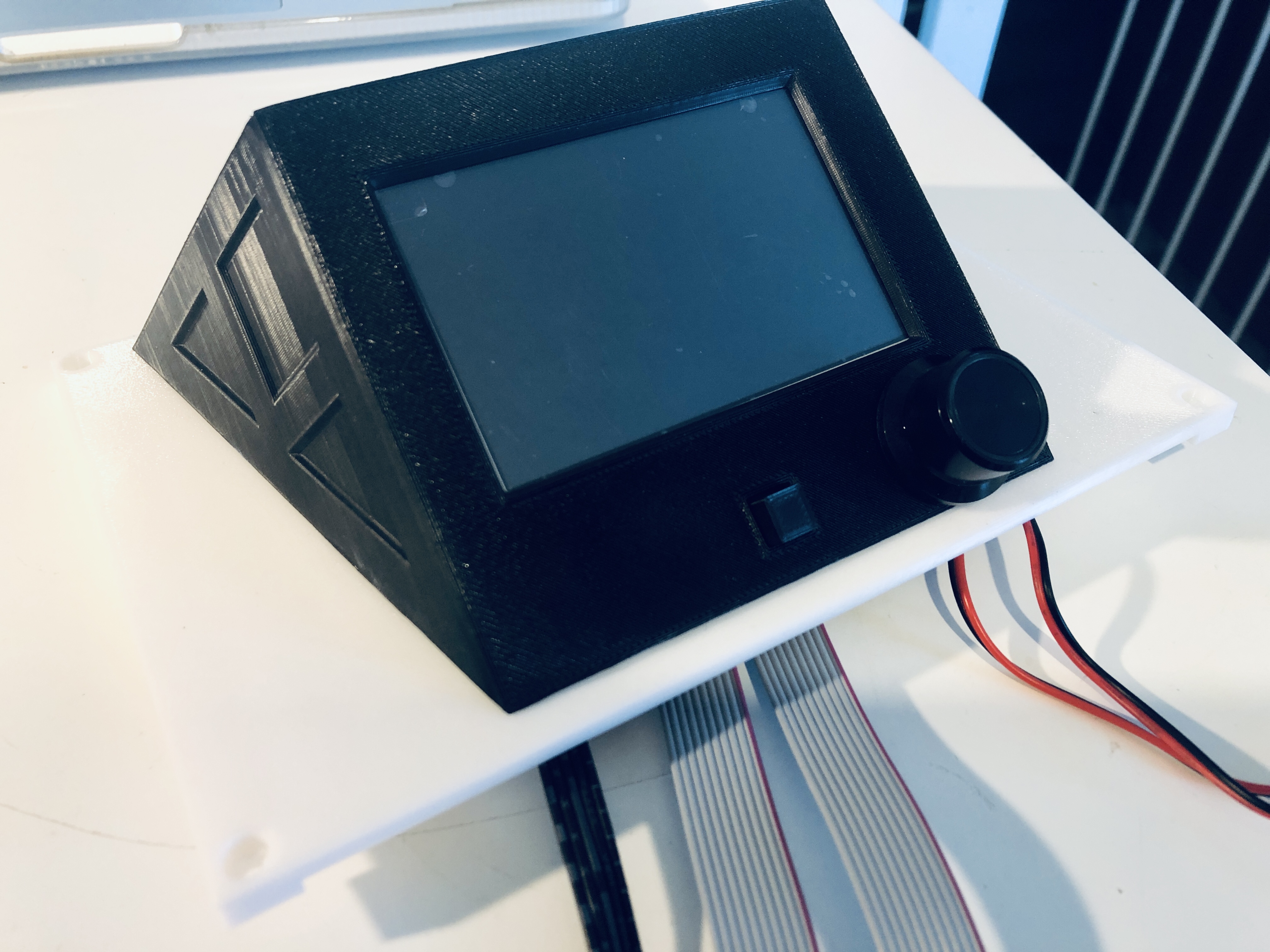
Made a start on the board and touch screen. Wanted to do something different, and start getting into the interface side of things.
Managed to get the board flashed, and updated the TFT with the newest build too. It took me a while to figure out the screen update, as every-time I plugged the card in and reset the screen, it would just go black. It was working perfectly fine with the build that was on there, Marlin and TFT modes were all good. It just didn’t want to update.
It was a brand new SD card that I bought just for this purpose, so I didn’t even consider it could be faulty. Eventually I finally decided I should probably try a different card “just incase”, and low and behold, it worked immediately.
Frustrating, but we got there in the end!
With that, I decided to start test fitting things into the case and start seeing it come together. Tested the fans (quieter than I expected), and decided to just hook them up to the main 12V supply going to the board (so they are always on).
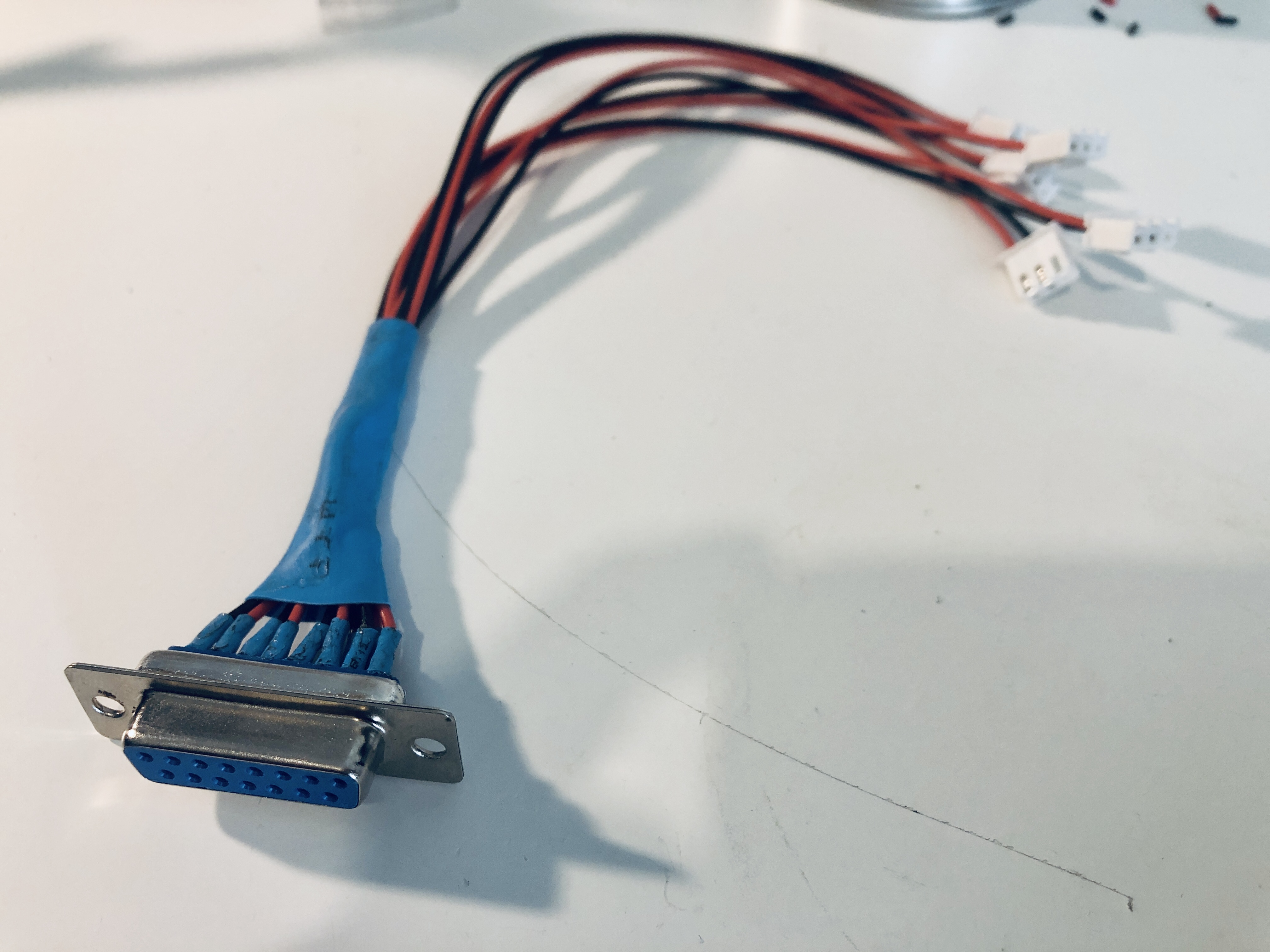
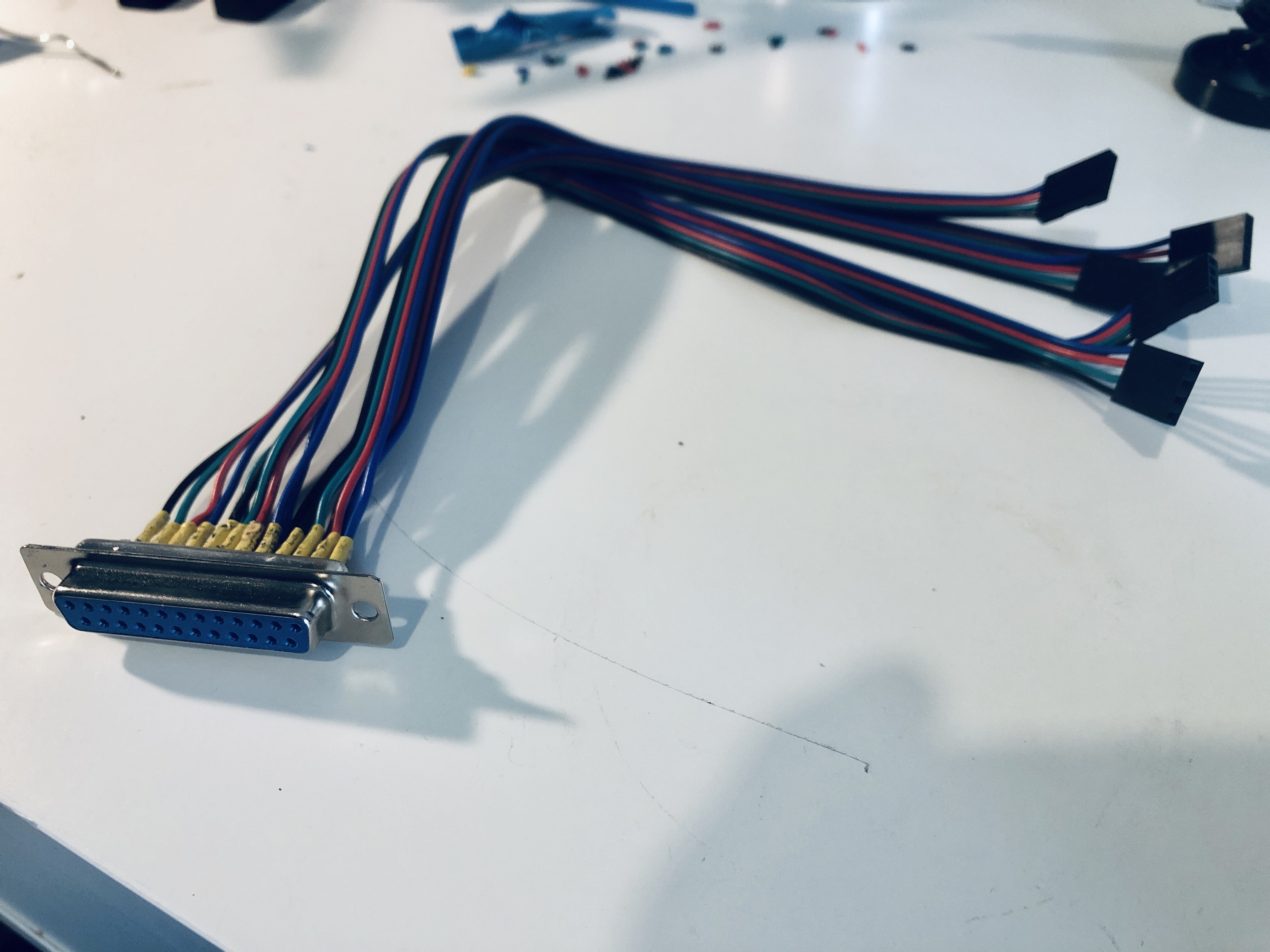
Now, I had the fun task of wiring everything to the D-Sub plugs.
I wanted to goto this effort as it really makes life easier to relocate the control box at a later date. I simply need to get some D-Sub cables to extend. Plus, it makes it easier to problem solve any issues with my wiring.
A little bit of advice, remember to label the wires before
heat shrinking them into a bundle haha!
I have wired a feed from the 12v power supply from the board out to the D-Sub. I’m thinking of adding some standard white 12V led strip lights around the frame to light up the work area. And if not, then I’ve got a wired 12v feed for anything else I may need ready to go.
I do have some questions around controlling the spindle through the board. I’ve seen people talking about it here on the forums, but nothing definitive seems to be there for the SKR Pro board. My other problem is that I also have a 10v feed on the spindle driver, and the SKR board has 5v PWM pins. If anyone knows of a straight forward guide/solution to adding spindle control to this board, I’d be really grateful to be given a link to it!
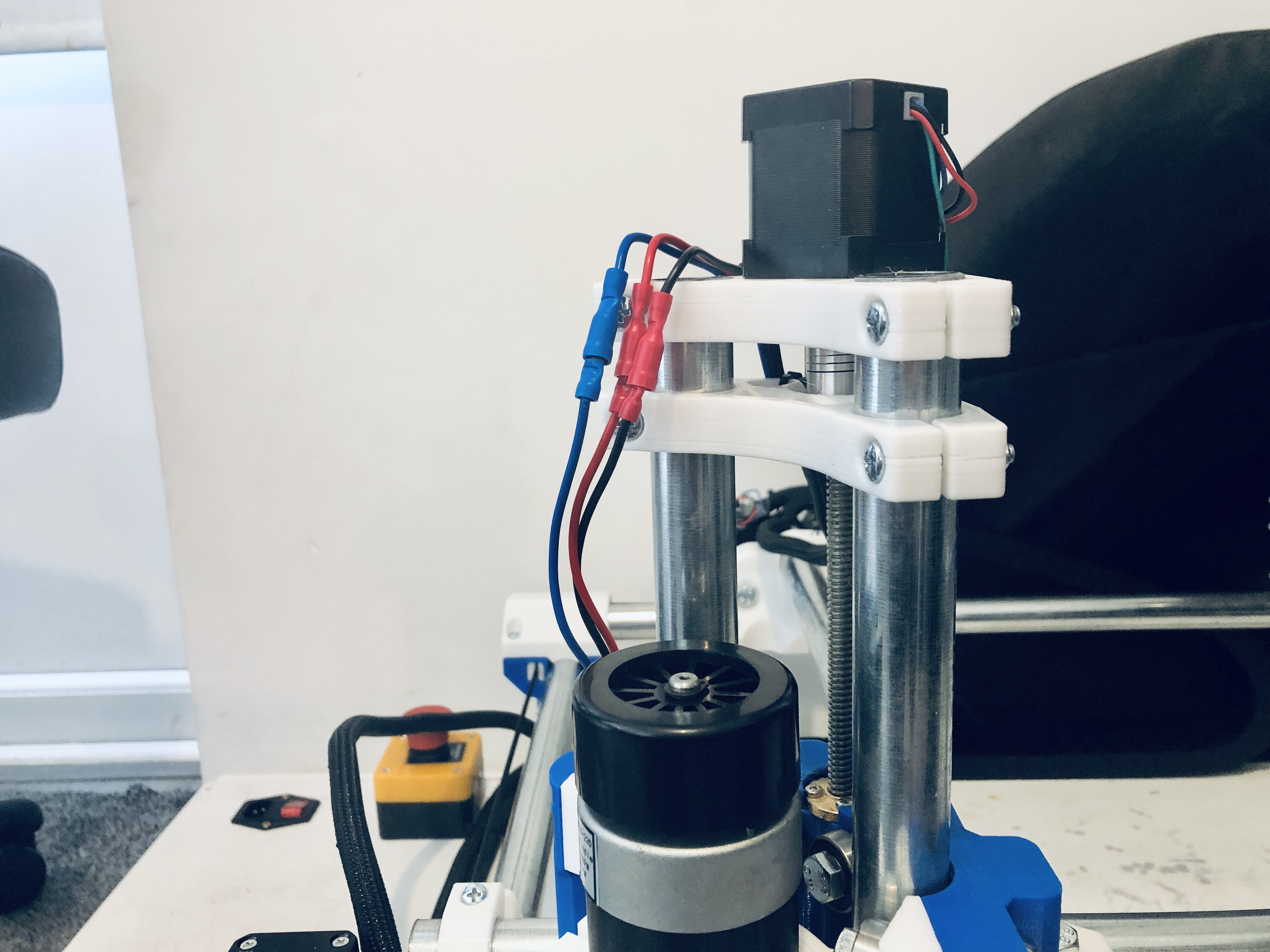
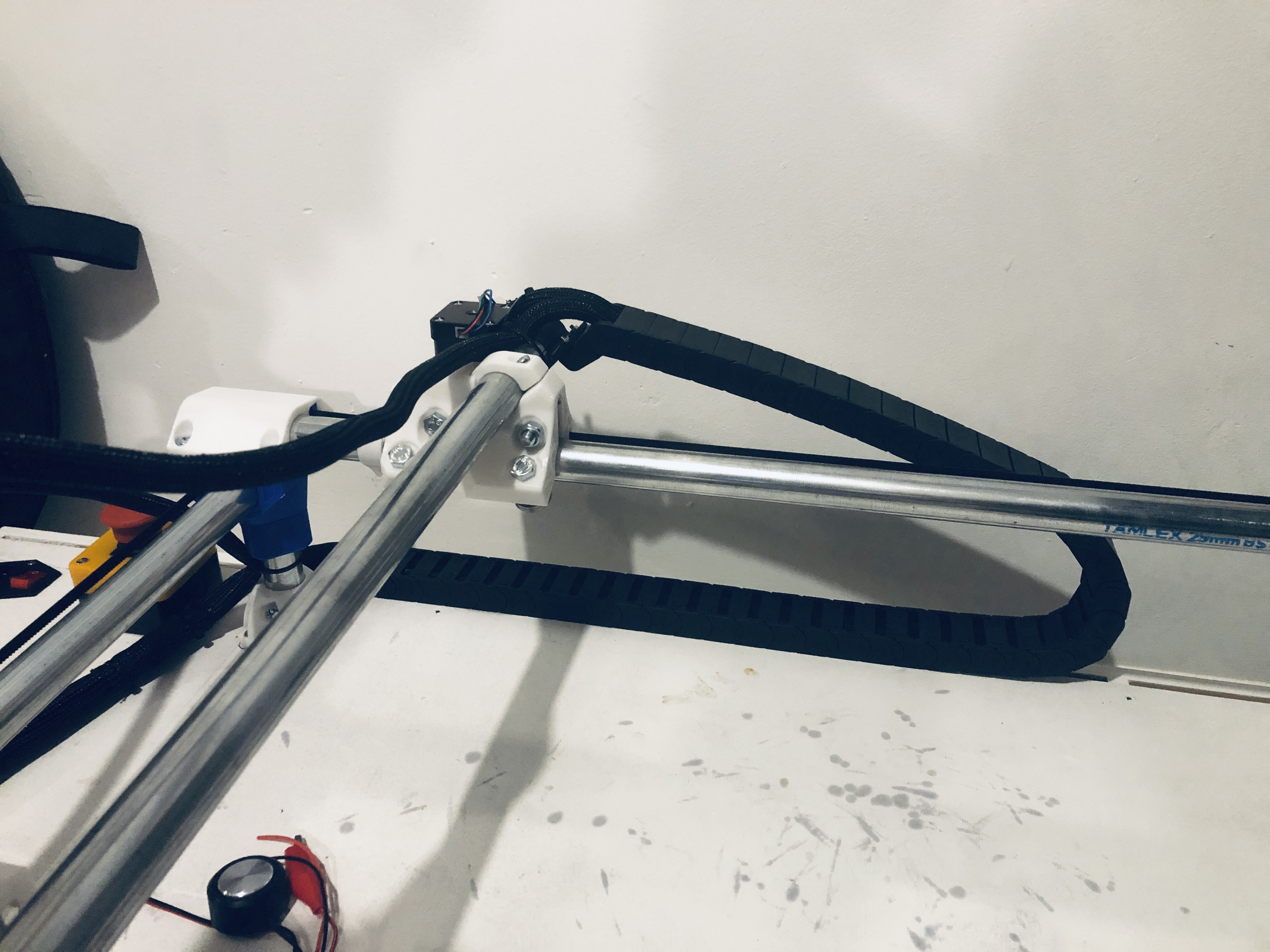
Lastly for today, I realised that I have wired in my spindle permanently, and didn’t really have a way of changing it out in the future. Or even just to remove it to add a pen/knife mount for example. So, used some bullet connectors to make a semi-permanent option for it. And, I also managed to install a drag chain for the two looms at the back. It now looks a lot neater, and is all finally starting to look like a finished machine!
I had to call it there on progress, as when I was changing the tip on my soldering iron, I managed to snap the collar that holds it all together. So, no more soldering iron. I have a spare, but it’s at the in-laws.
So, had to call it there for now.
Not much more to do. That crown is getting closer…
I made a real push on the remaining bits to do today. Spent some time tweaking, and trying to understand what the hell the instructions mean on the end-stop page.
Some visuals would be awesome there, because I’m still not 100% sure I’ve understood whether I measured the correct diagonals.
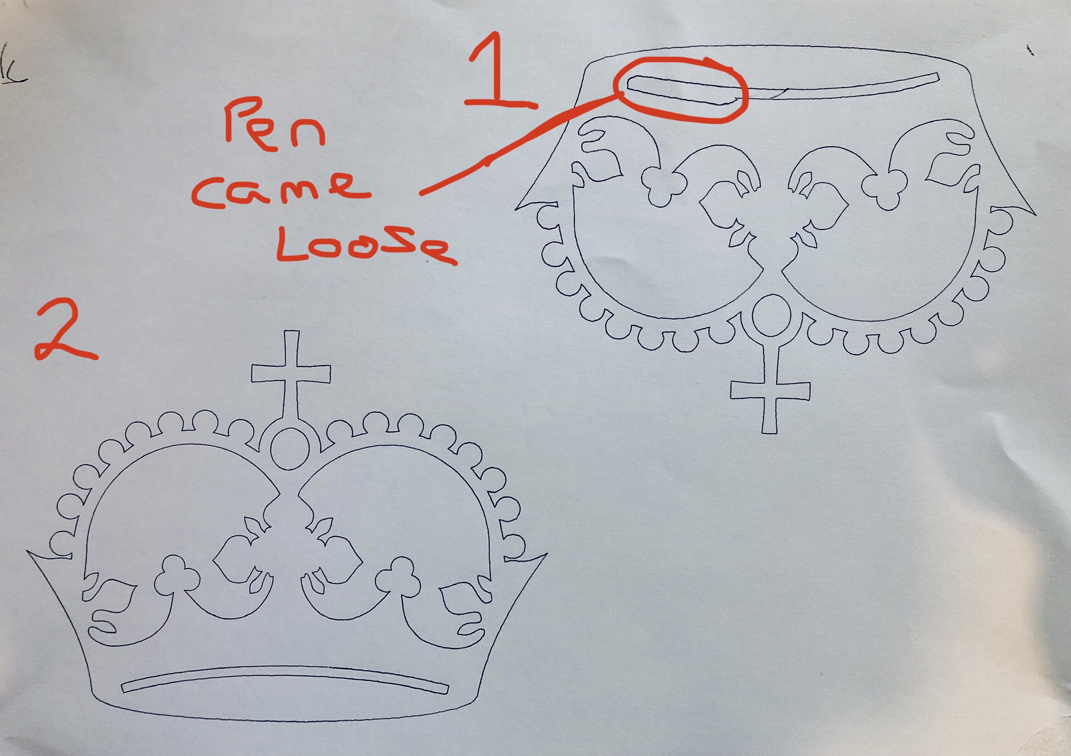
So, here it is in all it’s glory. I present, my first Crown…
(Well, technically first and second, as the pen came loose on the first one haha )
Thank you!
X is 57cm and Y is 29cm.
Was supposed to be 600mm x 300mm …but had to do some last minute adjusting to make it fit on the board. So, lost a couple of cms during the build!
How about cutting out some full depth parts to get the feel for your feeds and speeds.?
Start with some small things that you can see how fast you can run your machine and the relationships between speed and quality.
Coasters, letters, etc. look on Etsy for some easy projects. Don’t pick anything that take more than 15-30 minutes or takes a bunch of wood so you can have time to play with settings and not worry about making mistakes.
Put calipers on anything that can easily be measured and fine tune your alignment until your tolerances are good enough for you.
After about 2 hours of cut time check the bolts and tighten up the machine as something will have worked its way loose.
Looking good, props to using the D plugs, or whatever they are called. I have gone with aviation plugs. Got to solder them today.
My first cuts were drilling (boring) a spoil board to take screw inserts. Then some wooden clamps.
Then I took it to bits to make an enclosure, sawdust gets everywhere.
I got stainless steel pipe from Metals4u or metal4u in the UK, Bars all cut to length and delivery with a week.
Thank you! Yeah, the D-Sub’s were worth the effort I think. And I think future me will be grateful too!
Out of interest, what aviation plugs did you go for?
I have a spoil board installed now, but I haven’t gone for the hole drilling. For what I’ve been doing so far, I haven’t needed them so haven’t troubled myself with that effort…yet!
Oh, I do wish I’d had my pipe cut to size. I regret having to do all mine manually with a pipe cutter haha!
I went for 6 pin, 16mm dia. Four pins for the steppers and 2 for the endstops. I bought 12mm dia to start with but couldn’t see them to solder. I need new glasses.
 )
)

 haha!
haha!