Hello, I am French speaking and only speak very poor English. Excuse me !
Seeing the quality of the mechanical assembly explanations, I dared to embark on the construction of a CNC lowrider to use it, I hope to paint generative art canvases… A giant axidraw that could clean my brushes , select the paint from a palette, etc.
The problem is, I am incompetent in mechatronics!
I bought an arduino mega 2560 R3 + Kit Ramps 1.4 with Full graphics LCD 12864 + Power supply 24V 15A + 5 Stepper driver TB6600… + 5 nema 17 today I am very worried, because the Lowrider mechanics are finished, but I don’t have no idea how to connect the electronics!
I’m looking for help, but please help for Dummies! I can read an electrical diagram, but I really do not understand, for example, how to connect the motors, because I can find electrical drawings for 3 motors, but not for 5 motors… On the RAMP card I only see three motor locations?
In short, if anyone is willing to devote some of their time to guiding an ultra beginner, I would be HAPPY! Thank you in advance !
It is an interesting project you are building…and I’m sure your English is much better than my French.
Starting with the stepper drivers, the TB6600 is more than you need for the Nema 17 motors. So unless you are modifying the MPCNC with larger, NEMA 23 motors, going with a different driver will simplify your wiring and getting the firmware flashed.
The Ramps firmware maintained by V1 Engineering can be found here. The Ramps versions of this firmware are setup for the DRV8825 drivers, so going with DRV8825 drivers will be the simplest solution to getting your machine running. The recommendation on this forum is to set the vref voltage for these drivers to 0.7V. If the term ‘vref’ does not mean anything to you, you will find multiple videos on YouTube on how to set the vref voltage, plus there are also web pages on the subject.
There are two different wiring approaches, serial and dual endstop, and each has its own firmware. With serial wiring two motors share a driver, so a total of three drivers are used. A Y cable connects together the two motors for each axis. V1/Ryan sells these Y cables, but I don’t find them sold elsewhere, so you probably have to wire your own. You can find a wiring diagram for the serial Y cable, plus some other information on wiring the steppers in serial, on this page.
With dual endstop each stepper gets its own driver, so there are wires running from each motor to the control board. You don’t have to install endstops to use dual endstop wiring, but this wiring is reuqired if you want to do dual endstops now or in the future. And wiring your machine this will will save you from having to buy or make a Y cable.
I can find electrical drawings for 3 motors,
The E0 and E1, which stands for Extruder 0 and Extruder 1, are also stepper motor drivers. When wiring up for dual endstop, the second X motor uses the Extruder 0 driver and the second Y motor used the Extruder 1 driver.
In terms of actually running the wires, most people run the wires through the tubing. In addition, either a cable chain, sleeving or sleeving with the tape measure trick are used to route the wires along the side of the machine.
I’m not sure if this info will help you or confuse you. This forum is a friendly, helpful, and responsive place, so don’t hesitate to ask more questions.
Hello Robert… Thank you very much for bringing me valuable information.
Unfortunately with the ramps I received 5 x A4988 driver and it was not DRV8825 that was provided! Was it on a French-speaking forum that I was told that I had to buy the big drivers because my nema17 motors were too consuming in amps? (I didn’t understand anything) Model
17HS4401-S Type Hy-brids - Phase 2 - 1.8 ° pitch angle
Your information guides me one step forward, I know I have more problems than solutions, but with a user-friendly forum I feel less alone!
Then I’m especially afraid of breaking the electronics and even more afraid of having made all these purchases of equipment in vain!
In addition to the questions of electronic connections that scare me, the questions "how do we do? " are numerous.
You would be, I think, surprised, you who know so much that a beginner (66 years old) finds complicated!
For example I started this project, but I wonder if things as simple as: every time I have done 10 dots of paint, I have to go and dip the brush in the paint bucket is possible!
I will have to search a lot …
Precisely, my ultimate goal is to create INSPIRED generative art from paintings of Australian Aborigines.
Thanks for your empathy Robert!
The A4988 drivers will work just fine. The only issue is that you will need to modify the firmware to support these driver. It is not a big job to change the firmware, and many people on this forum can help you. On the other hand, locally DRV8825 drivers are inexpensive. I can get 5 of them for $10.50 USD, and it might be worth the cost to not have the work of modifying the firmware.
Then I’m especially afraid of breaking the electronics
The Ramps boards tend to be delicate and have a higher failure rate when first used. On the plus side, typically what fails is the Arduino Mega clone board, and locally they only cost $15 to replace. So you if something happens to your electronics, it is relatively inexpensive and easy to fix.
I would suggest getting your board up and working without the drivers installed. Then make sure the stepper drivers are connected to the control board before installing and adjusting the stepper drivers.
You could get the electronics and the steppers running before installing them on the MPCNC just to be comfortable that you are on the right path. Just be sure to never fire up the stepper drivers without the stepper motors installed. That can damage some stepper drivers.
the questions of electronic connections that scare me, the questions "how do we do? " are numerous.
I would suggest you use a dual endstop configuration where each stepper has its own connection to the board. After you start, I think you will find it not as complicated as it appears now.
For example I started this project, but I wonder if things as simple as: every time I have done 10 dots of paint, I have to go and dip the brush in the paint bucket is possible!
Very possible, but in addition to getting the electronics running you will have to figure out how to author that movement. The authoring tools are designed for milling with a router and cutting with a laser. You will have to “fool” them a bit to get the motions you want.
and even more afraid of having made all these purchases of equipment in vain! my ultimate goal is to create INSPIRED generative art from paintings of Australian Aborigines.
This is a very cool idea! Yours is not the first use of the MPCNC for painting I’ve read about on the forum. I have no doubt that you can get the MPCNC running, but you will probably have some additional engineering to do to make it work as you want. Things like avoiding paint drips, and getting the movements right for a stroke. An then there is the whole authoring end of things.
Also, never plug or unplug motors with the system powered on. Safest to always unplug the RAMPS from power (including via the USB plug) before making wiring changes.
I’ve had a couple boards where I had the driver installed but no motor attached and that didn’t cause an issue, but unplugging while powered on has cost be a couple of A4988’s.
There is another option, you could use an additional motor as an “extruder” and have paint “pumped” into a brush. I have seen lots of people use 3d printers for decorating food. I would imagine it’s not that different. Then you wouldn’t need to author the gcode to make it dip the brush. But you would also want to not use the v1 firmware.
@Atom Thank you for this idea, but then, I would also have to imagine a mechanism, a kind of barrel, which would allow me to change the syringes with the different colors! Anyway, I am still not reassured about my ability to program tool movements, I am looking for tutorials for beginners and often the problem is that we speak from expert to expert. I discovered that the CNC is really something difficult in terms of documentation, in particular because I am French-speaking and except for the translation software, I have really difficult to understand technical English … I often finds that obvious and simple things for a connoisseur are puzzles for the beginner!
I think authoring the movements would be difficult unless you (or someone that owes you a favor) knows how to code and could create a post script(a program that you run after the g code is made, that will edit the gcode to do somthing different) for you. If you did it yourself you would have to go through each program count the number of dots then add the the commands to tell it to dip the paint brush again. It would be long and tedious.
Not as difficult as you may think. If I was building it, I would use syringes that are filled with paint. The machine would paint everything for the first color than it would pause for a tool change (this is built into the firmware, so it’s easy to do) then I would pull out the seryinge with (let’s say) red paint run a cleaner through the tube to clean the tubing and brush. Then install a syringe that had yellow paint in it and tell the machine to continue. It would be very similar to doing a “filament change” on a 3d printer.
Also I have lived abroad in a country that I did not speak the language. So I am familiure with working through a language barrier. If you need somthing explained in less technical terms let me know (you can message me directly if you want) and I would be happy to help.
@robertbu Hello, before building the lowrider I had dreamed of a CNC system for art. I built the machine because I do quite well in traditional mechanics … But I have never succeeded in having the machine recognized on a COM port while my 3d printer is automatically recognized on a COM8 port. As on the French-speaking forums people laughed at my shortcomings … I imagined that the LOwrider CNC would be easier to connect electronically!
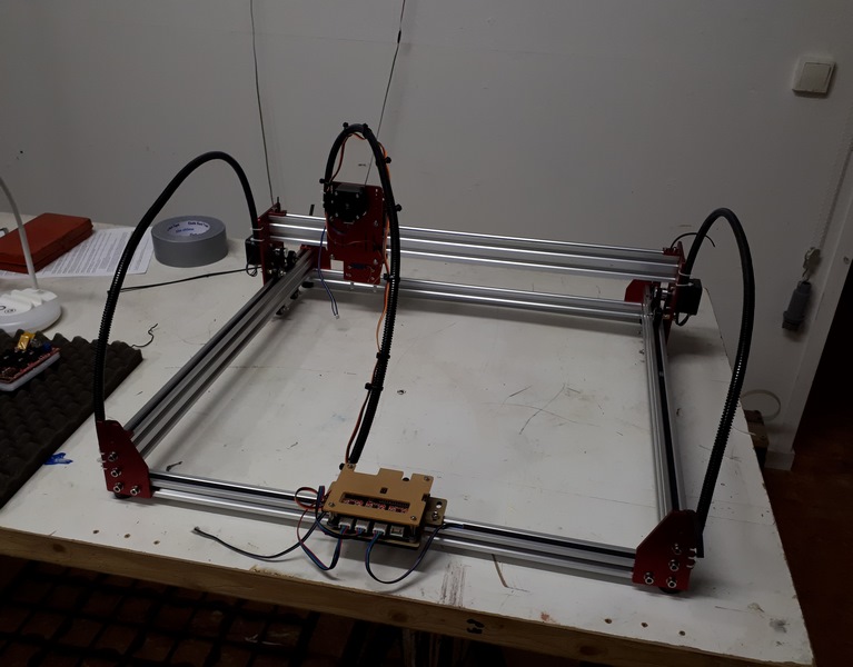
Thank you for all your advice, I am busy drawing a box for the electronics and then I will 3D print it … I am coming back to you to ask you if my TB6600s are still not less fragile than the A4988. I am worried about burning electronics …the photo shows the machine which has never moved … maybe I should make a work of it in the spirit of Marcel Duchamp and call it “The one who does not move!” 


@Atom Thank you it’s quite surprising the kindness that reigns on this forum, no mockery as I have known on French forums where I was told “give up” I explained myself poorly, I know how to read Gcode and modify it for my printer 3D, I program (not as an expert) in processing I know how to do loops and conditional for example … What I do not understand at all is … I make an analogy … when I use my 3d printer, it’s the slicer that creates me dozens of lines of Gcode … If I manage to get the Lowrider to work, will I have to write all the lines of the Gcode a bit as if in the case of the 3D printing I didn’t have the Slicer ??? I hope I made myself understood thanks to the translator
Based on their specs (I’ve never seen or used one), the TB600s are likely less fragile than the A4988. With that said, and given the settings that are used for the MPCNC/LowRider machines, it is exceeding rare to get an issue on the forum that turns out to be a failed stepper driver. Sometimes builders manage to damage a stepper driver when they are setting things up, but once installed, they just work…and this included the A4988 drivers.
When I’m building something that I’m unfamiliar with, I’ve found that the path of least frustration is to start with the simplest solution I can and then build outward to things more complex. Even if you plan to use the TB6600s long term, I suggest starting with a simpler driver solution.
If you use the DRV8825 drivers, you can have your electronics up and running in an hour (assuming no hardware issues). There is a pathway for setting up your hardware that does not require any compiling. The stepper drivers plug directly into Ramp board, and the stepper cables plug directly into the drivers. The only significant piece of work is setting the voltage of the drivers.
If you use the A4988 drivers, things are a bit more complicated. You will need to make firmware changes, so you will need to setup the tools to compile the software and you will need to change a few lines of code in one file. Electrical connections are just as easy as the DRV8825 drivers. Assuming things go well and you don’t have any hardware failures, you could have your electronics running in a few hours.
If you use the TB600s, the electrical connections become a lot more complicated. Here are a couple of wiring diagrams I found for wiring up the Ramps with TB660s. One, Two. There are a lot of ways you can make a wiring mistake that would cause things to not run, and unless you understand how all the wiring conceptually fit together, it could take you a lot of time to figure out the issues.
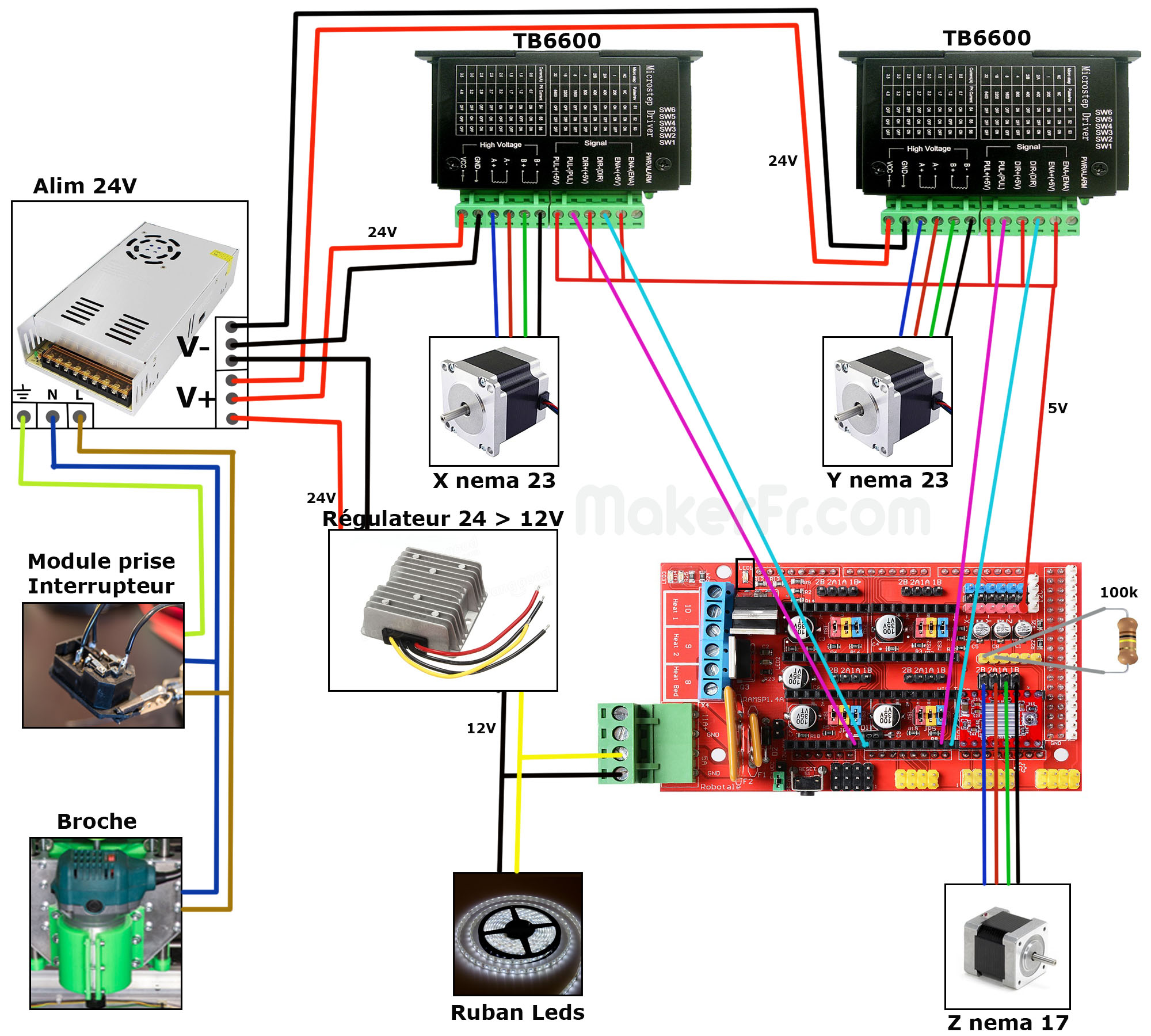
So I suggest you take either the easiest route (DRV8825s) or the slightly harder route (A4988) and get your machine up and running. Have the satisfaction of watching it move and drawing the crown. Then after you have used it a bit, you can decide if you want to go to the extra work of wiring up the TB660s.
P.S. After you have the LowRider running, I’ll bet you can go back and use a similar electronics solution to get your original machine running.
Why not trying to make an eggbot? That’s my plan 
On a more serious note - your topic makes me think of this guy that makes abstract art using concrete and other medias. I don’t know if he’s using a v1-inspired machine any more, but he did at one point - and I think you can find him here in the forum, but I don’t remember any relevant keywords. He might have some input? On instagram you find him as https://www.instagram.com/g.kindermann2019/
When using a CNC machine the “Slicer” portion is referred to as CAM. The CAM software takes a model and allow the definition of tool paths to use. CAM defines how the router moves. The problem for you is that CAM is designed for moving a router around to cut the wood or a laser around to burn wood. It is not designed to move a paint brush. To use CAM you will have to “fool” the software to get it to do what you want.
I use Fusion 360. It is professional CAD/CAM software package, but there is a limited version that includes some sophisticated CAM tool paths. It is complicated software, but you would only have to learn a very limited portion of it. There are simpler tools that may also work for you. When I looked at examples of Australian Aborigines. art, I found a lot of paint dabs. In fusion 360 CAM, you can drill holes. That drilling includes things like pecking motions that clear the hole of material. So you could author a line of holes drilled along a path with a particular motion and depth. Then when you use a brush instead of a router, the g-code will move to each place where you want to dab paint, and then move the brush up and down. You could even define some “drill holes” that result in the brush being reloaded with paint.
I don’t have an understanding of the art you want to achieve, so it is impossible how much of it you can achieve by “fooling” CAM software vs. doing custom software. There is also a middle ground, where you use CAM to author the original file, but then edit the file before running it. It is an interesting journey you are on.
@robertbu I’m going to order DRV8825 drivers … I looked at the two diagrams which seem understandable to me so I keep this possibility if it works with the DRV8825 drivers … You write "If you use the DRV8825 drivers, you can have your electronics up and running in an hour "but I believe that there are also jumpers to install and on your two diagrams there are not 5 motors it is the same with the diagram with the 1.4 ramps I did not find no longer with 5 motors! it actually disturbs me to tell me that for example on the “Z” axis if I understand correctly, the two motors must be perfectly and level and synchronous! The hardware is finished, I still have to make a table and then we will see … All this precious information guides me, it is very useful even if I must seem to you completely incompetent!
@turbinbjorn more of this … my dream…my dream machine (https://www.youtube.com/watch?v=HFfHfxrugeU)
Beautiful example!! So that machine works with a paint pump and no brush at all. That is great because it means you could use an open source system that already exists like this one: https://www.stoneflower3d.com/projects/clay-extruder-prototype/.
As for your work flow (the process of taking an image and turning it into the gcode that the lowrider will understand) that will be more complicated. I feel like your best bet would be to take your original image and turn it into a limited color dot matrix (you should be able to find a tool online to do that pretty easily). Then take that dot matrix into a somthing like Adobe Ilistrator and separate it into separate svgs based on color. Then use CAM to covert each .svg into gcode. Then author the gecode to replace the normal moves with extrusion moves with the extrusion speed being how much paint per second the device will layout.
Inskscape is an open source vector and raster illustration program for which a number of different CAM tools have been developed. Eggbot/Spherebots, CNC generation, machine embroidery, and even knitting machines can use artwork from Inkscape, run it through plug-in (many programmed in Python) and have it output through a variety of mechanisms. It may not be as big a step as you’re contemplating to get to a gcode output for a pigment spray tool.
Gcode is not very complicated, as I am sure you know. I can imagine a script that looks like this:
- lift the brush
- move to a wash bin
- lower the brush
- move the brush back and forth a few times to “scrub” the brush
- raise the brush
- go to a specific color
- down
- up
You’d end up over the paint bucket at a height above the work.
You could take that script and use it is in you CAM as a tool change script. The CAM should make sure to connect that to moving to the next part and lowering down to the work piece.
It certainly isn’t easy. But it is possible.
At some point, taking a piece of art, forcing it into CAM, using CAM to mark all the features and then managing the color changing scripts is more work than just writing your own program to write the gcode.
Wouldn’t you want to do all of one color before continuing to the next color? Or do they have to overlap?
@robertbu Hello Robert… the drivers will be delivered in 5 days! I am impatient ! Can you tell me (with simple words of course) what T0 is for a thermistor … what is it for and what is the value of T0 because I have to order some also THANKS