Off topic printer help

Started thinking really hard about pinter calibration after reading a post by @dkj4linux (at least I think it was). I think I’ve been doing it wrong all along, messing with the standard steps calibration I learned about from the untamed internet.
Here is the result of a little head scratching and 4 hours of printing/measuring, plus a couple more hours for the actual piece.

Aside from the slight warp in the corners there, this is perhaps the nicest thing that’s ever come off my machine. I didn’t even brush away and of the crud…straight from the bed.

That front hole is supposed to be 4.3mm for an M4 bolt, but it’s 4.3 side to side. Top to bottom is exactly 4, and after messing with my slicer i can see that it’s because of the 0.16 layers cutting off the hole. I printed another one for giggles at 0.08 and I got it up to 4.23.

Now I’m not sure if I should go through the model and tighten up any of the measurements, because the 4.3 seems like an awful lot!!!

Yeah, I probably won’t, but I could…

1 Like

Not sure what you may have read from me… but please DO NOT try to calibrate your 3dprinter steps/mm from a printed piece. If you have a decent/reputable printer, it’s almost surely loaded with firmware that has the appropriate step/mm settings already set for each axis.

3d printing a test piece involves an extruder, and about a million settings for the extrusion process… and even though the head/carriage may be properly positioned for each move, the extruder is squirting out strings, blobs, and bits of plastic in a manner that can easily result in wrong dimensions of the resulting piece. Much more often than not, it’ll likely to be something related to extruding the plastic than the steps/mm, that results in a over-/under-sized printed test piece.

I trust my 3d printer… it’s proven time and again to be trust-worthy. I don’t mess with it.

Regarding steps/mm setting… I also build a lot of DIY machines, with different drive methods, controller boards, and firmware. I can’t trust them to move correct distances at all, when first put together. So, as soon as I can power the machine and get an axis to move consistently and repeatably (no loose grub screws, etc!) to a commanded move… I actually measure it, with a good ruler, a rubber band, and a skewer. Strap the skewer to the carriage with the rubber band and lay the ruler underneath and in line with the axis you’re trying to measure. Align the skewer point with a major division on the ruler and command the 10mm move… and see how far it actually moves. If you can safely make a bigger move – say 50mm – then command a 50mm move and then measure it… the larger the better. Nothing printed or routed… just eyeballing a measurement.

Then it’s a simple matter of adjusting the current steps/mm setting according to the following:

(commanded move / actual move ) * current steps/mm setting

That’s it regarding steps/mm setting. After that, any physical printed/milled/routed piece’s dimensional errors will NOT be due to steps/mm setting… look at the extruder settings and/or CAM instead.

– David

1 Like

I tried to find the post, but gave up. The forum sure is busy these days!

At any rate, you said something along those lines (if indeed it was you). Something about a machine being off by almost 10 percent on step/mm was a major problem, and that perhaps a percent at most might be expected.

The “standard” advice I’ve gotten (and unfortunately followed until early last week) was something like…
1)measure your filament through the extruder over 100mm, calculate the steps and update it.
2)print a single-wall cube with no top and measure the wall, adjust the flow rate until it matches the nozzle
3) print a cube and calculate the xy steps/mm.

I can see a few reasons why that’s not a great way to do it, now, but I never stopped to THINK about it until you mentioned a machine being in good repair. The first problem is that it’s really hard to measure EXACTLY how much filament goes through that extruder, especially to the precision that the stepper can execute. The second is that there is ALWAYS some measurement error, especially by a schmuck like me. After that, like you said…plastic is unpredictable and will blob, expand, shrink, etc.

All the parts on my printer are commercial, and all the important characteristics are well-defined…angle/step, teeth/pulley, etc. If something isn’t moving the right amount, it likely needs a tuneup. So, I reset my software, broke out the dial indicator and did some measuring. Ended up tightening the belts a little more than I thought I should, but I got so close to the measurements I expected I felt comfortable that I just had some measuring errors and left the calculated numbers in it.

After that, the blobby/oozy part was all that I had left. That’s where I started scratching my head. I’m still not sure about the nozzle diameter influence, but I reasoned that the slicer must care more about the width of a line than the actual nozzle diameter. In Cura, there isn’t even a nozzle input anymore. So I measured a bit of plastic from the nozzle and used that instead. Then if the printer isn’t laying down the right dimensions, it’s GOT to be because it’s squirting out too much or too little plastic.

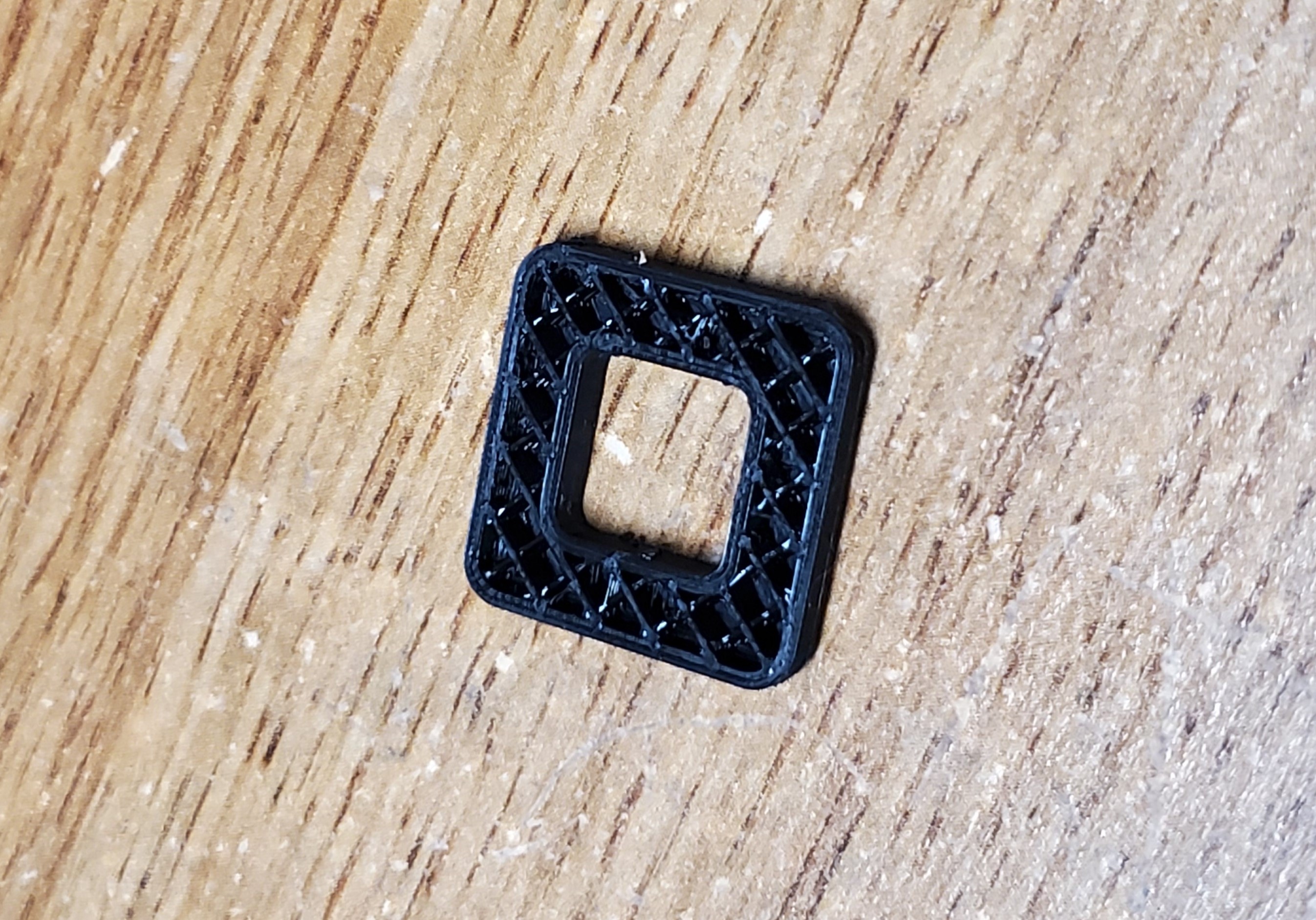
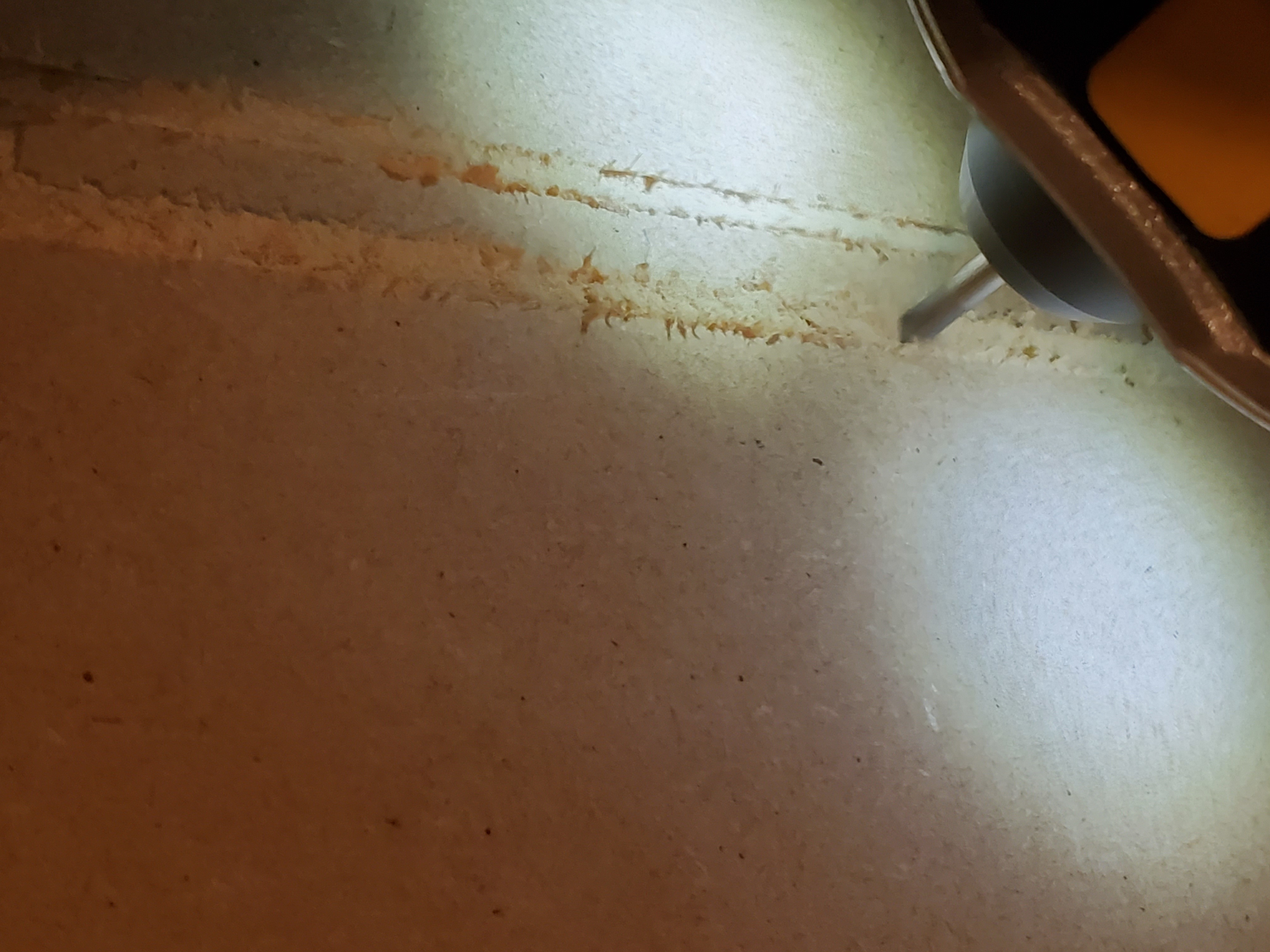
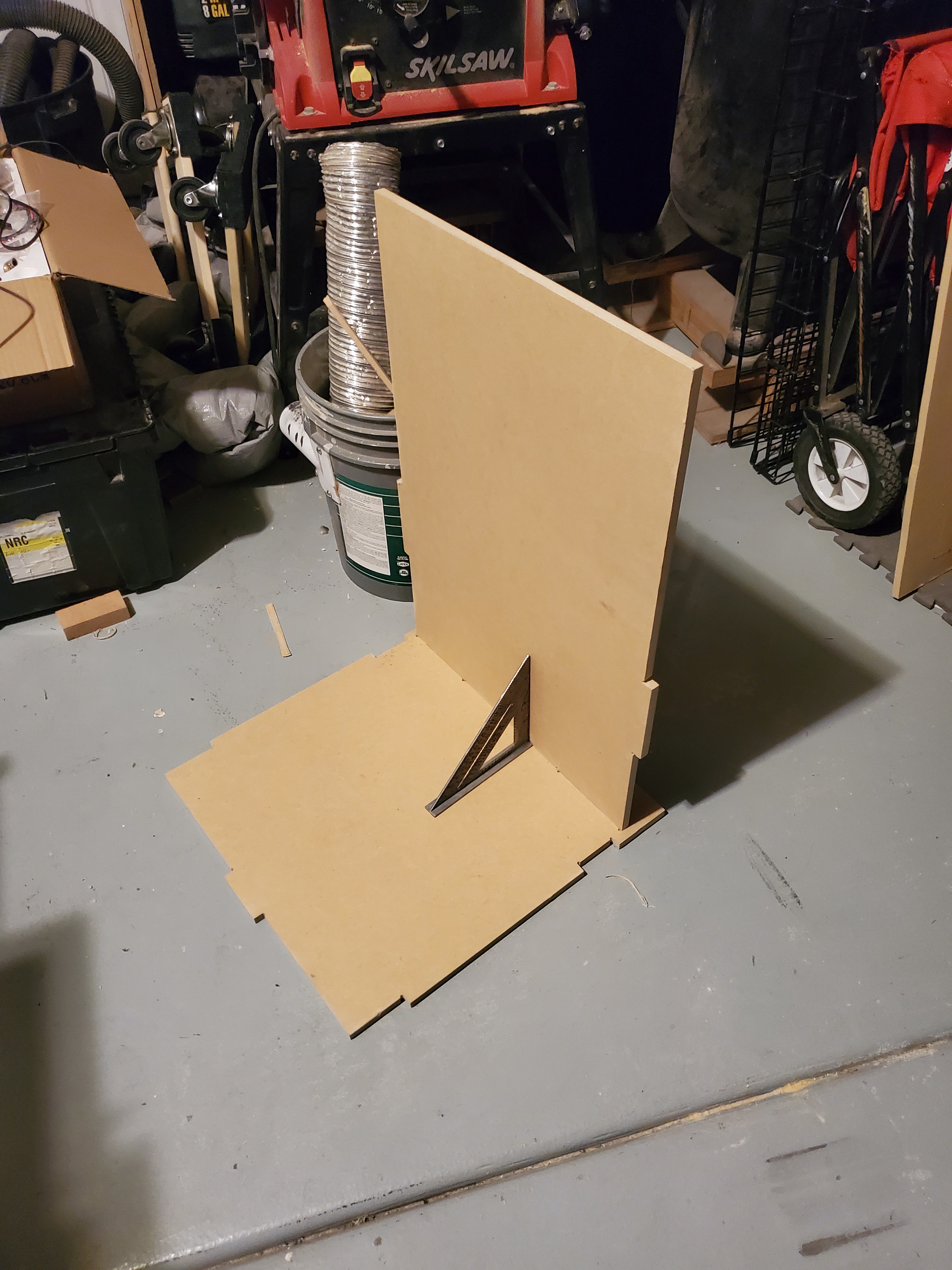
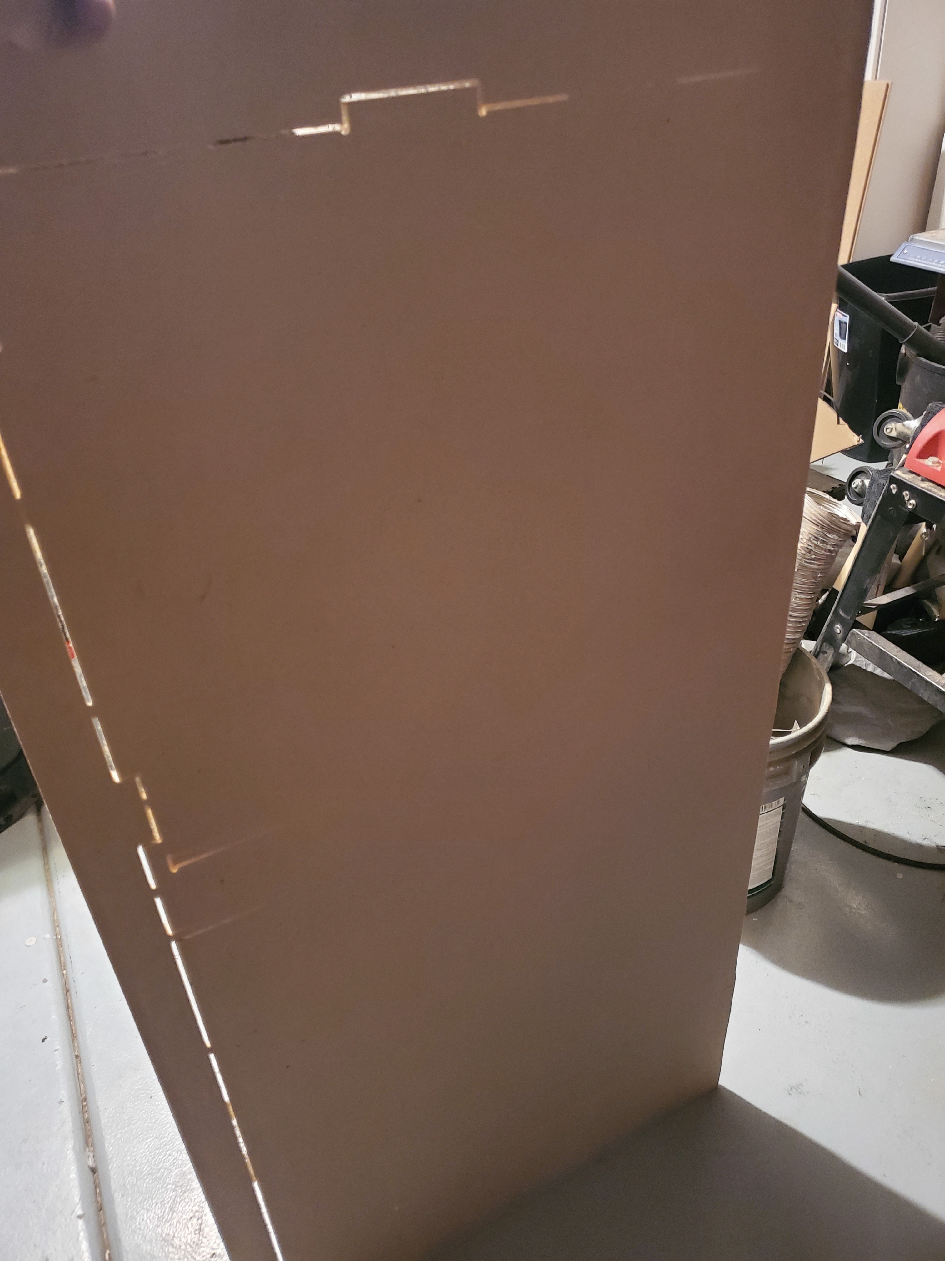
I made a quick shape (picture below) thinking that overextrusion would make the outer measurement too big, and the inner too small…by the same amount, and vice versa for under extrusion. Lucky me, that’s exactly how it turned out. I was going to use a circle, but remembered the whole deal with polygons and didn’t want the possible error. I was just going to plug and pray with the flow rate, but since my algebra needed a workout I drew a picture, made a variable, and boom half the error + the extrusion width all divided by the extrusion width is the percent of over extrusion. The reciprocal is probably closer to the correct flow rate. Plugged it in, bang-stupid close to actual dimensions.

Anywho, here is a picture of the shape I used. The inside should measure 10, the outside 20. If they aren’t off by the same amount, probably the steps aren’t right. If they are, any difference is in the extrusion. The corners are rounded because @vicious1 pointed out to me a little over a month ago that square corners ALWAYS blob (re the primo calibration test), the bottom is chamfered because elephant foot, and I printed without a top because speed/material.

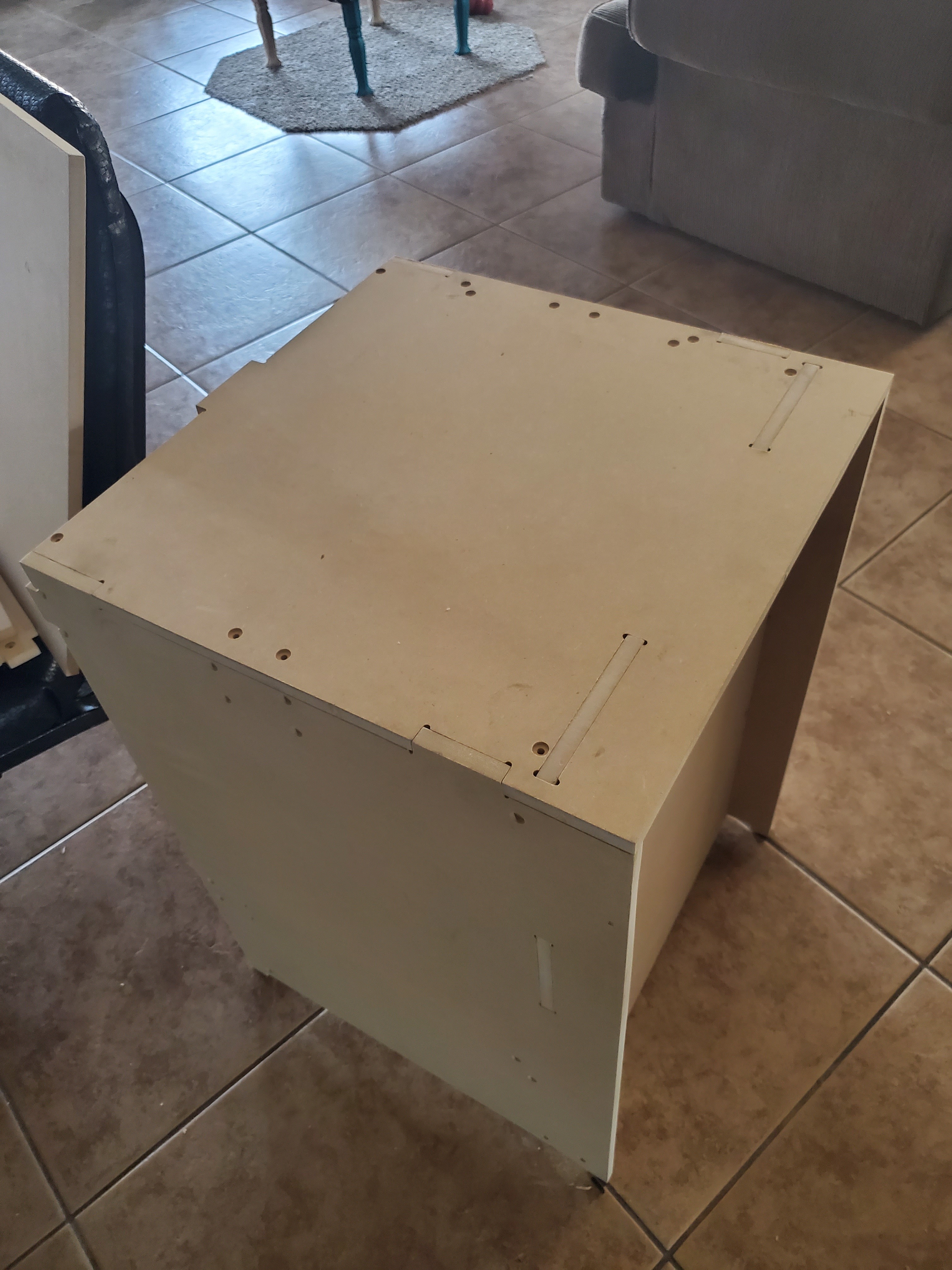
Of course, as is the way, I found this on thingiverse over the weekend. The inside shape and outside shape are the same measurement, so it might be easier the think about, and the outsides of the arms are 20mm apart, so it does all the same stuff mine does, PLUS if you print two, you can try to fit them together for a test without measuring. Bonus, somebody made a calculator for it. Like, 4 years ago. Before I even thought about getting a printer and listening to bad advice about setting it up.

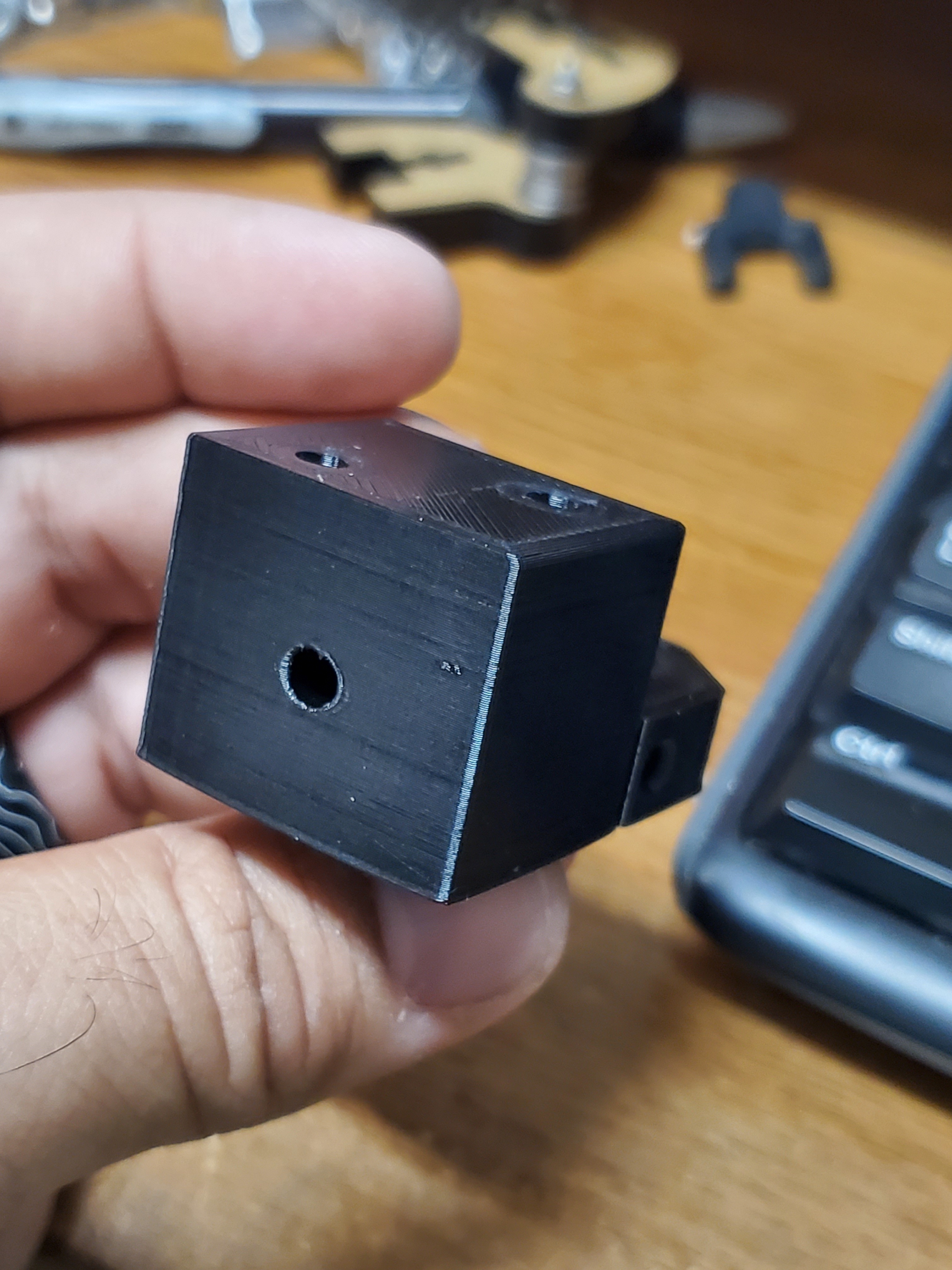
Anyway, that was the journey, and I can’t argue with the result. I’m the guy that brings something to measure pipe at the store because I can’t eyeball a 1.25 pipe from a 1.5 (had to fix a sink earlier tonight, lol). I mean, put them side by side and I know which one is bigger, but hand me one and ask which it is…better be printed somewhere. And I’m measuring a 4.3mm hole that’s exactly what I modeled within the error on my digital calipers…I’m a happy dude.

2 Likes

I apologize for any confusion. I was thinking more of the XYZ steps/mm than the extruder steps/mm. I’m glad you’ve figured it out… and are a “happy dude”. I’m happy for you! :smiley:

1 Like

No need to apologize. Awful lot of people doing things exactly like I used to, which s the whole point for me. Thank you for kicking off that thought in my head.

1 Like

As far as 3D Printing goes, it’s been my experience that X, Y, and Z motion are pretty easy to “get right” as long as there isn’t a big source of mechanical trouble (loose grub screws, anyone?). The biggest source of variance for me has been with the plastic extrusion. I think this is due to the (forgive the term) plasticity of the feedstock. Lot’s of stuff impacts the final extrusion product, and many of them interact with one another:

  • stepper motor steps per mm (coarse feed adjustment)
  • extrusion multiplier - name varies by slicer (fine feed adjustment)
  • retraction settings
  • linear advance/coasting
  • stepper motor amperage (can lead to pulse/moire patterns)
  • tightness of “pinch” to drive the filament
  • diameter of nozzle
  • temperature
  • desired speed of extrusion (can the hot end melt it fast enough)
  • specific material, even different colors of same material can react differently
  • height of nozzle above bed or previous layers
  • room for hot plastic to spread

And, if you try to tune these in a bad sequence, you feel like you’re on a merry-go-round where stuff you thought you’d fixed got bad again.

I’ve found Teaching Tech 3D Printing Calibration Guide useful as a process to work through. He provides specific tests, downloadable gcode (similar to the crown test @vicious1 has made available), and instruction on interpreting the results. He does warn you when things interact and you may need to revisit a topic (e.g. temperature tuning and retraction and linear advance).

2 Likes

Yeah, so, my bolt depot order showed up, extra pulleys showed up, belt showed up, heat set inserts showed up. I have 4 parts printed.
And Autodesk said no more step files. Autodesk said a lot of things, and I’m not sure if any of them other than no rapids and no tool changes will affect me. But I’m also not sure if I’ll use 360 forever. So, I started cleaning out my files to make it easier to export them now, just in case i switch.
And my computer crashed. Looks kinda the mb, got an RMA from Asus, but now I gotta work on my laptop to expirt stls for the printer (they were on the main machine). So that sucks.
Upside, the nuts snap right into place on the parts I finished. Yay for small wins.

Still waiting on the motherboard, but at least Asus had it now and claims it is being repaired, so that’s good.
Got the rest of the parts printed and started cutting some panels tonight.


Kind of a bit bigger than I thought they’d be.

Also, tried to give myself a little extra room on the zero because of my clamps and almost ran out on the other side!


I had to double check features I’d already cut a pass on to make sure I didn’t actually skip steps… All good!

Tabs fit and hold the board up right.

Now I just have to drill some of the holes through and cut the rest. My machine isn’t quite trammed and left 50-60 thousandths on the bottom, not cut quite through. Top left of this picture is just still packed with sawdust.

I have no idea how this little bitty printer ended up with such a large enclosure. I’m starting to worry I somehow scale something accidentally.
But really, the reason I’m here is because it slotted together just like I’d hoped. Even if I have to scrap it, this is a win for me!

5 Likes

Naa, keep it, most folks migrate to bigger printer eventually anyway.

1 Like

Wow those are some clean cuts. That almost looks like something from IKEA. Nice work. I am excited to see how it turns out. This tinkering is a lot of fun.

1 Like

Got some work in, turns out it’s the right size, just kinda big relative to the build plate. If I did it again, I’d put all the motors on the outside, and that would help a lot. I need some more skills first. The hotend carriage is also rather large and takes up more room than it needs to, but I wanted to use as much of the anet kit as I could for this one.

Thanks, I really am pleased with this. Came off a super sized primo, too.
Turns out one of my printed parts is warped and the xy is noticeably un-square, so I’m printing another and calling it a night. More pictures tomorrow.
New motherboard showed up, too, so hopefully I can get my pc back together. Instead of repairing the old motherboard, asus sent a picture of a crack in the board. Checked the picture I took before I sent it off, and it’s there too. Don’t know if I broke it on the install and it kinda worked for a while or while I was troubleshooting, but either way I broke it so they couldn’t fix it. Replacement asus board would be 2 more weeks, so I got a gigabyte instead. Hope this goes smoothly.

1 Like

Well, this is promising!

Pretty sure all the mechanical bits and bobs are in place. Forgot I want the lid to swing up, so it’s cut with the same friction fit as everything else. Hopefully I can shorten it without screwing it up.
I spent way too much time messing with wires tonight basically because I don’t want to do it. The anet kit means all the wire ends are bare, and I’ve never wired a printer (only mpcncs), and I’ve never wired a heat bed, and I’ve never done corexy, and this archim board was pricey.
I’m certain at the end I’m say “that was all?” just like everything else.

3 Likes

The archim builds were broken for a while and they were fixed (by Ryan’s prs) in 2.0.7.1. I don’t know what older version they were working in. I think it might have just been working in bugfux momentarily, and didn’t make it into a real release. But I’m not sure.

We have one that should work for the mpcnc in MarlinBuilder releases. I would at least grab that to have a reference. But it will be pretty wrong for a printer.

1 Like

Oh crap, I didn’t know that. Maybe it’s better to plug the anet board in. Upside, if I toast it I’ll be upset, but not enough to need a drink.
Thanks for the heads up.

2 Likes

Plugged in the anet board. Might have been better to run all the wires to the front and put the control board/display at the top in front, or even the bottom, but I wanted to hide all that mess and keep the lid as large and clean as I could.

I say might have been better because the Dupont plugs don’t feel very secure in the anet board. I still have them, but boogered up one of the endstop plugs trying to see how the wires fit. I’m trying to avoid soldering, but if I keep this board I’ll probably want to put the anet plugs back on. Might add some Duponts to the cut ends of those, but either way it’s starting to get silly.

And now I’ll need to find a project for that archim.

As for the printer, it all moves properly as long as the plugs are in. Well, as properly as you’d expect considering the firmware is Cartesian lol. I had a video, but it wasn’t interesting.

Hopefully I’ll find a decent box for the board in the morning and have it printed by the afternoon, and spend time after work setting up the firmware. Might not be until Wednesday, because wifey needs me to set up some signs on the teeny tiny.

1 Like

I am excited to see it come together. For those DuPont connectors. Try putting some electric tape around the connector before you plug it in. That will make it wider/thicker so it might hold in place better.

For one of the Timber bot builds I want to do I will be using a board that I kinda broke in my Ender 3. It was an SKR e3 mini. Good board. But I touched that printer and had some static shock burn out the X stepper driver. Sigh. So I will use it as a laser engraver and repurpose the E Driver as a replacement X.

It’s an inexpensive board that works really… well when it doesn’t have to defend itself from an office chair that charges you with 1.21 Gigawatts every time you stand up.

Thanks, that’s a good tip and I have PLENTY of electrical tape. I’ll be sure to take a decent video once it’s reading gcode.

Also a good idea on the laser. I think I have enough room on this one to run a dual extruder so I might play with that to make better use of the archim later.

I do have a diode I was planning on running on the primo (worked great on the lowrider, hanging off the vac duct) but I’m short on space. Maybe a zenxy standing up on the wall with the laser instead of a magnet? That could be cool.

The electrical tape worked surprisingly well.
Couldn’t get the marlin 2.0 bug fix to compile in arduino ide, finally gave up.
Found a walk through for platformio, not bad.
Couldn’t get the full graphic controller to work on the anet board, gave up. Apparently the power and ground are swapped so there needs to be an adapter…can’t swap them back with the pins file. I’ll build an adapter when I understand the pins better and restock my Dupont junk. With the board behind the machine, I’ll want access to the SD slot on the controller, I think.
Of course, the anet lcd only gave me white boxes when I plugged it in and reflashed. I read some things that said it’s either the mainboard toasted or the lcd quit. Took fifteen minutes to realize I’d edited a copy of the config mistakenly. Fixed that up, the display worked…and none of the buttons seemed to be recognized. Not kidding, I just about quit right there. Started looking for that archim because configuring that was looking pretty straightforward!
Anyhoo, started looking for an older version of marlin, and downloaded the release version (2.0.7 or something, I think). Boom, problem solved.
Them I just had to sort out the motion. Not as straightforward as Cartesian, but I got it! Now I just have to measure the home offset and wrap it up.

2 Likes