I’m sure I can spend some some tomorrow trying to find a good resource, but I spent SOOOOO much time today trying to figure out how to build Menu (which I didn’t solve) that I’m just tired of searching lol.
I’m happy that it works well enough. Wife epoxies cups, but those cup spinners are 30+ EACH. I’ve got a design of me own that works for 15 using similar stuff (and works WAY BETTER), and with this cheapo getup I can probably get it down to 10.
So the goal was to control them via timer because why not?
Not sure what problem you are asking for help with. A menu seems overkill unless you just want the learning experience. I’d just hookup a potentiometer to an analog pin to control the speed. Max current at 5V is around 150ma, so you can just barely power one stepper directly off your Arduino nano, but not two. If remember correctly you’ll get a max RPM of around 12 at 5V for these little steppers. You can probably double that by jacking the voltage to 9V. I wouldn’t go beyond 9V.
Oh, it all works. I just need to box it all up. I posted a while back about wanting an arduino project, so that’s what happened here, lol. I didn’t think you could run a stepper from a potentiometer, because they need digital signals, no? Do you take the analog and convert it to a step speed?
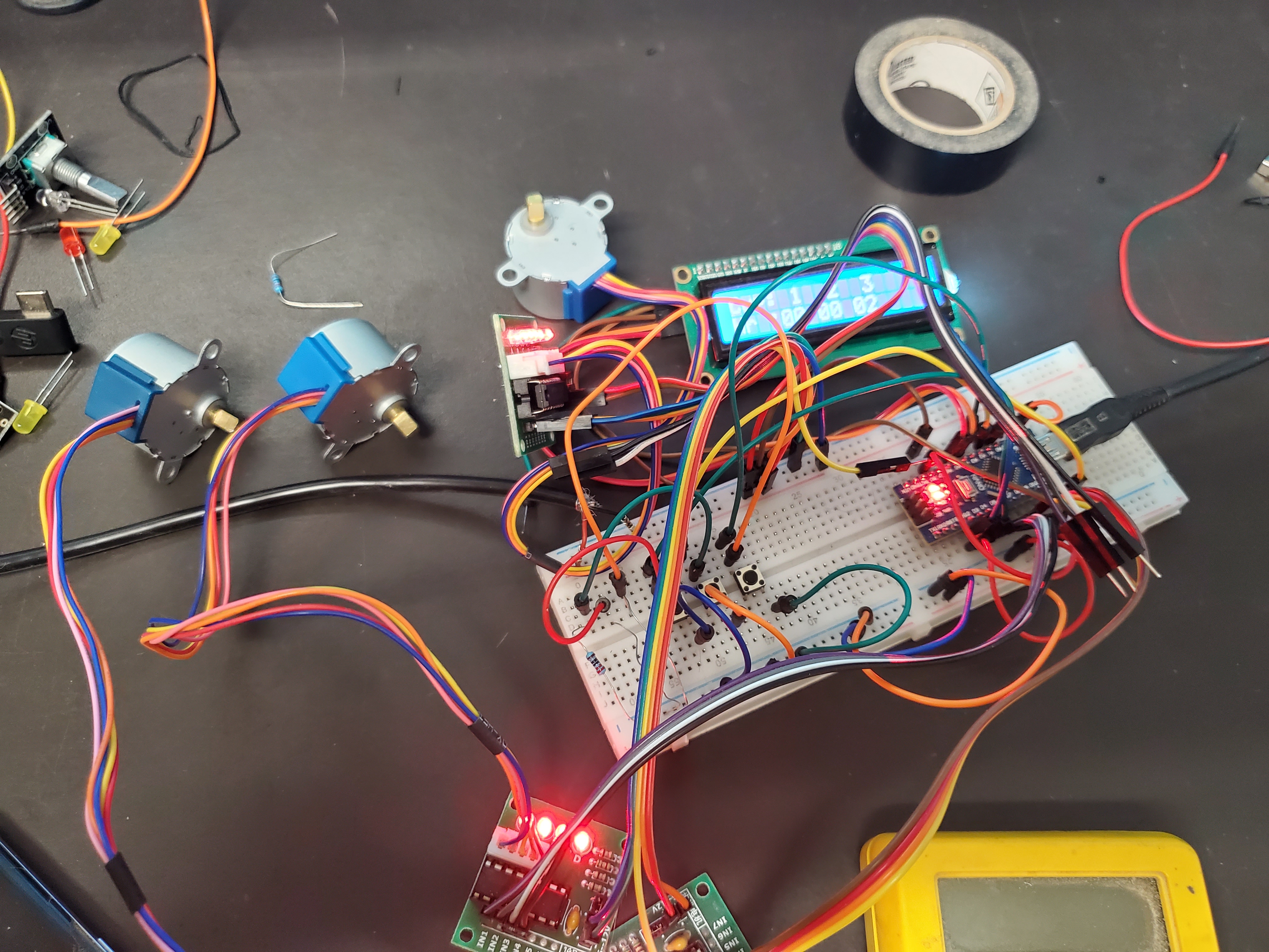
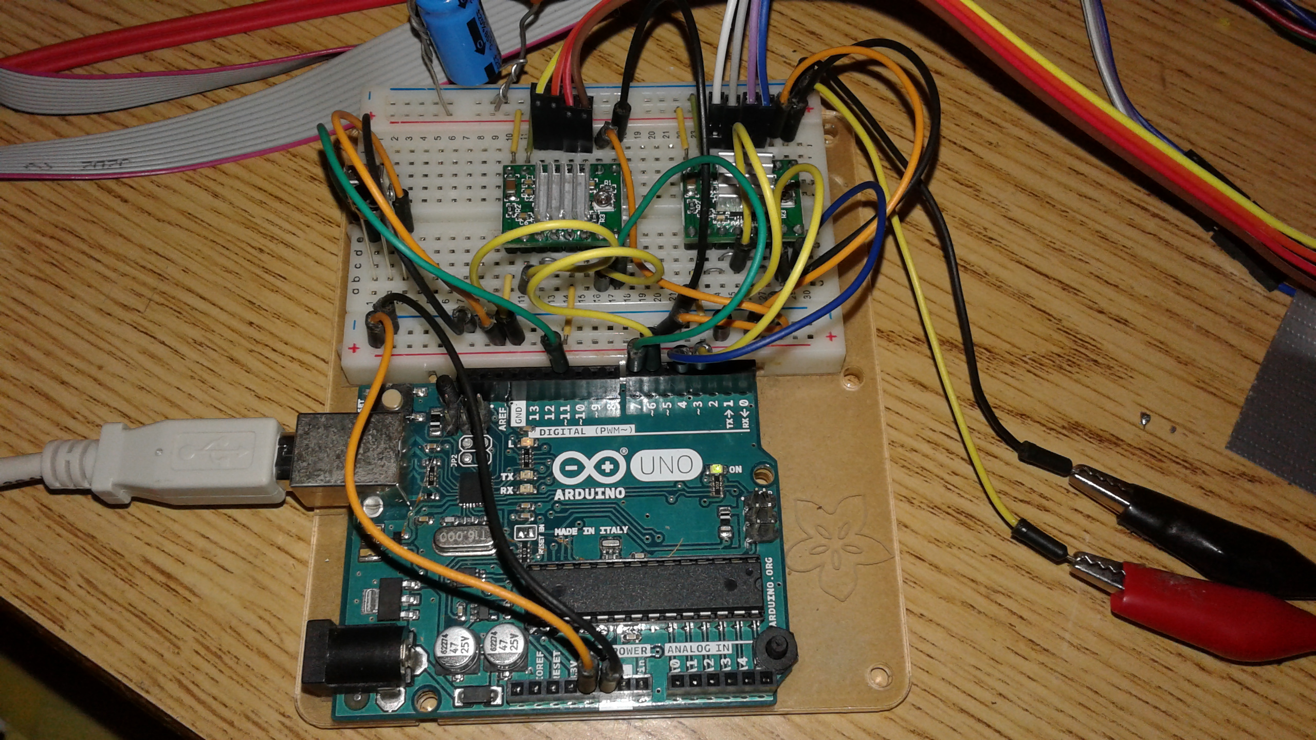
The arduino is controlling 3 drivers which are turning the steppers. The buttons add time (or turn off the steppers). The power is coming from an old phone charger.
I just done want to throw all of this in a heap inside the box. Need to tidy it up a bit. Or do I?
I didn’t think you could run a stepper from a potentiometer, because they need digital signals
You read the value from the potentiometer using an analog pin. It will return a value in the 0 to 1024 range (usually it is more like 20 to 1010). You map that value to something you can use to control the speed. If you are driving your stepper directly (not using a library), then you will will be using a delay between steps to control the stepper speed. An easy way to map these values is the map() function you will find in the Arduino reference.
I can tell you how I’d approach tidying things up, but it is just my personal choices.
First, I like to use an expansion board for my Arduino Nano for projects when I have space and when they are under development. If I screw up and blow the voltage regulator or burn out a pin, I can just unplug the Nano and drop a new one in. And it makes it easy to salvage all the parts if things don’t work out. And it saves some soldering and makes it easy to changes things around. I’m not suggesting this specific link for a purchase, just point out what one looks like if you don’t know. See Here..
As for the buttons, I’m partial to membrane buttons rather than tactile buttons when they make sense. They come in a number of different configurations. There is no fussy mounting. You can just glue the membrane down on a surface. Another visual reference link. There is at least one library (probably several) for reading membrane buttons since they are typically matrix wired.
I’m not sure what the resistors are doing on the breadboard. If they are pull-up or pull-down for the switches, then you can eliminate them and use the INPUT_PULLUP to have your input access the internal pull-up resistors in the Arduino.
As for a case, I typically 3D print mine. You can find models for all the components you have in this picture out on GrabCAD. I bring them into Fusion 360 and design a case around the components.
Oh, and I’ve learned through hard lessons to provide strain relief for the wires. Typically that means using low temp hot glue to glue wires down.
I’d agree, if it were me, I’d skip the menu, skip the timer, and add a potentiometer to an analog input to control the speed.
Also if you don’t mind them all running at the same speed you can drive all those ULN2003 from the same signal pins, meaning you can have an unlimited number of spindles from a single controller.
Experiment breadboard like that is great for prototyping, but not so great to put into a box. I know that there are good tools out there to turn that into a nice PCB, but I usually end up hand drawing a schematic, then using some CAD tools to turn that into something that I can etch (Or, I guess now mill) into copper. I use Eagle, but there are some reasonable free tools. I used to print onto transparency and used photo-resist boards. Cover them with a laser-printed transparency, expose to UV light for 15 minutes, then dunk into a developer, and etch. The fun part was always the drill press to get through holes afterwards. There are a bunch of arduinos in the car, and even more on the desk. I bought a bunch of Mega 2560 boards when I started 3D printing, because I fried one, and got a deal on (I think) 15 of them. Then I got a bunch of Unos, and some Leonardos when I was doing my MAME project… You get the idea.
Anyway, breadboard for a finished project is a recipe for disaster. All you need is for one of those jumper wires to fall out and get plugged back in wrong, and you’ll be better off starting over from scratch. Put pin headers onto copper and solder it up. Since you’re here, I trust that after that, making a case for it is something that you can deal with better than the people I talk to on the Arduino forums.
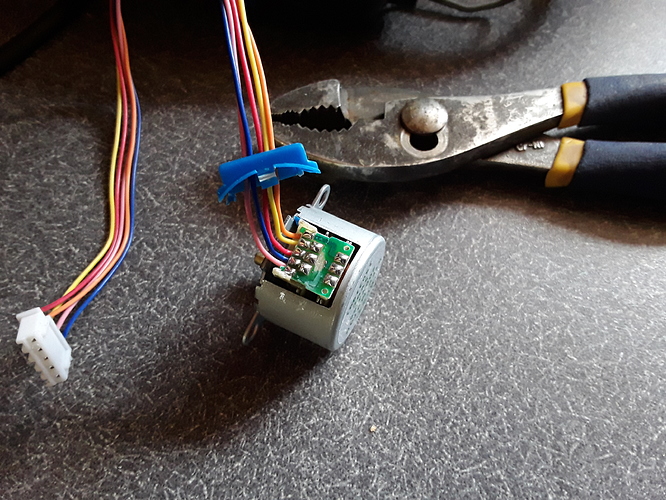
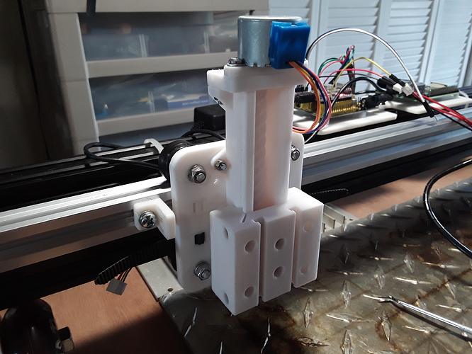
WHEN you get ready for a bit more torque and want to set up something more akin to the basic CNC we all know and love, there is a simple unipolar to bipolar “hack” you can do with those little motors and they IMHO become imminently more useful. You then ditch the little ULN driver boards and use our beloved stepstick drivers, A4988 or DRV8825. I’ve used these little motors to build several light-weight printed Z-axes for my laser machines.
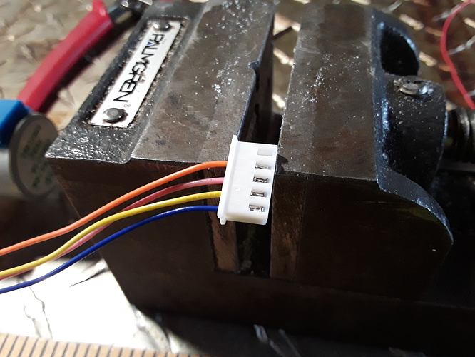
The hack is simply cutting one trace under the blue plastic cover, snipping and removing the unnecessary 5th wire, and rearranging the pins in the connector to match the stepstick driver outputs…
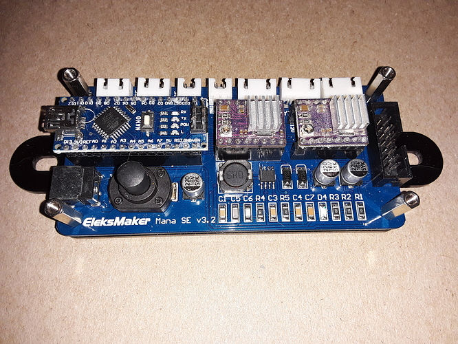
The electronics then becomes similar to this inexpensive CNC board… a Nano (loaded with Grbl or custom) and 2 or 3 A4988 or DRV8825 drivers to match the number of “axes”…
or this 2-axis breadboard version, which used an Uno with a couple of DRV8825…
I may actually have gotten something like that in one of the kits
Exactly. I’ll learn about the internal resistors.
Don’t think i would have thought about that, thanks.
I already know what speed they need to turn, so there’s that. The timer was a request from the wife when I started taking about replacing the rotisserie steppers she was using with something like this. I was trying to find ways to make it better, and that was just something she wanted.
All at the same speed is fine, all at the same time is not. Her first requirement was that if I were going to build a multi Turner that they NOT be all on or all off. My first plan was to use the bigger motor she had and just run a belt to all the pulleys, boom done. But if we have a motor for each cup, I have a plug for each cup. Looking back at this project, it would have been easier to just wire all the switches to one plug, in parallel or something, however it is in a house. But then she wouldn’t have the timer. And the motors would cost more (offset the arduino stuff, more or less).
I guess one set of control pound per driver is easy enough to solve by controlling the power instead, right? Run a relay to that side with some of the saved pins? It would simplify the sketch a little, and then she could have TEN going. Have to upgrade the power supply, lol.
Bottom line, this has turned out to be some great learning and a fun time, but probably not the most efficient use of either the time or the money. But I always knew it would go that way.
Sure seemed that way, so I came for help!
Sure can, as soon as I know what I’m putting in it!
And @dkj4linux…holy crap! I’ve noticed how torquey these little guys are and I read about all their applications, but that is NEXT LEVEL. Really really cool, man. I’ve got some extra Drv8825 drivers laying around, and I might crack one open just because they are so cheap.
Breadboards are notorious for flaky electrical connections, so I agree that using them in a finished project is a bad idea.
Personally, I usually use perf board, or strip board to turn a breadboarded project into something permanent.
This being a CNC forum, it should be noted that your CNC could be used to cut traces…turning a bare copper clad board into a custom circuit board. I haven’t done this yet myself, but I’m sure I will eventually.
Some old school approaches to more robust (than breadboard) circuits are “Dead Bug” and “Manhattan” style construction.
I like dead bug style for small projects with just a few components. A bit of heat shrink over the “legs” so they don’t short on each other, and a larger diameter bit of heat shrink over the whole shebang can make a crude, but tidy package…