Portable Primo ~24in x 36in (PNW) / 3030 Aluminum Extrusion Adaptor

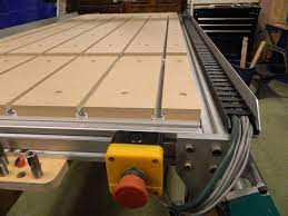
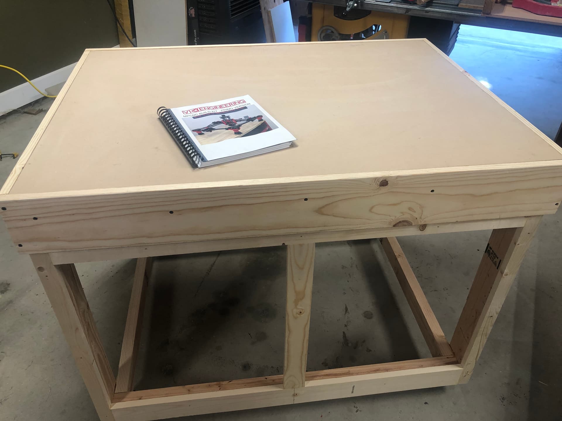
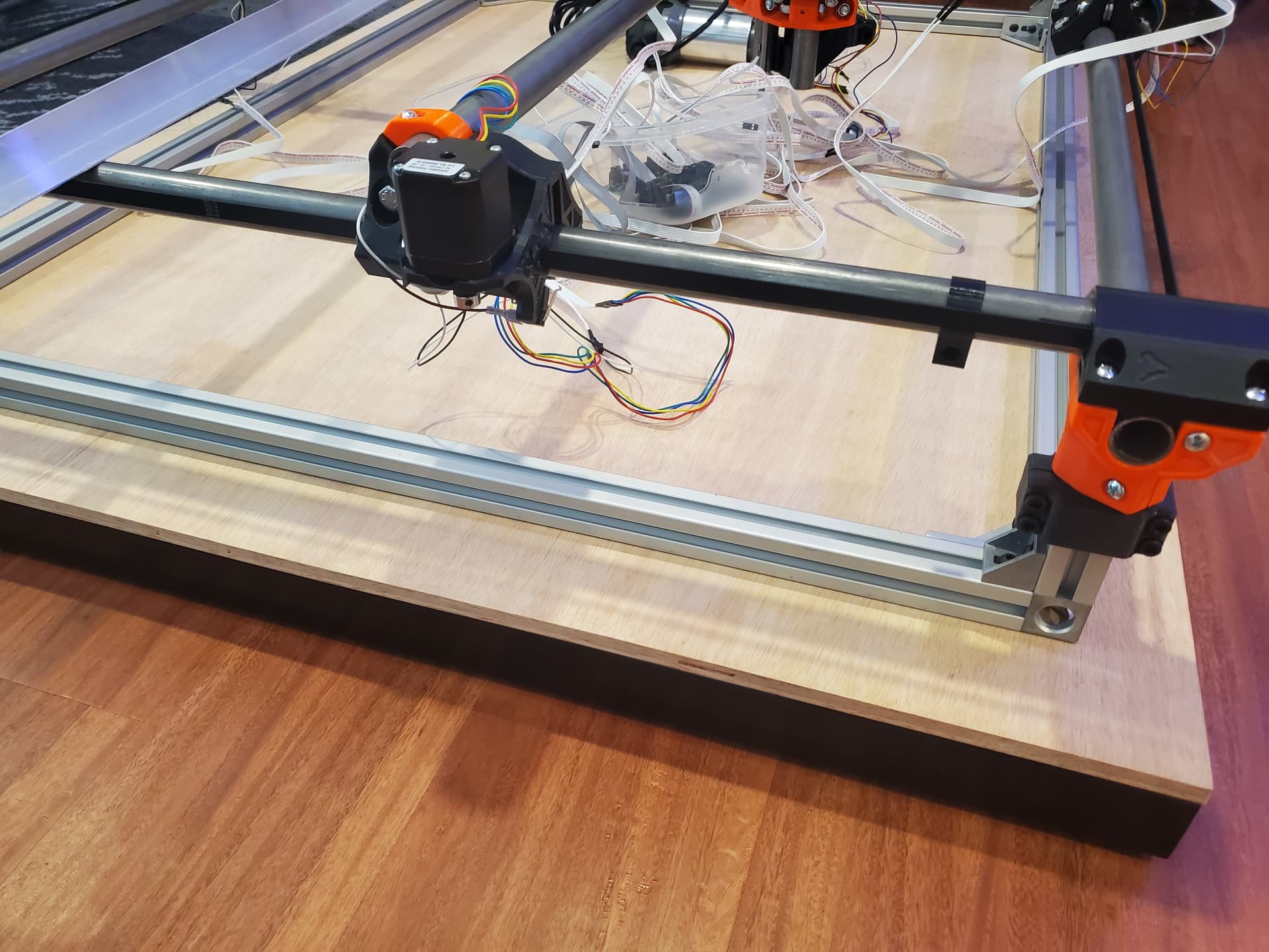
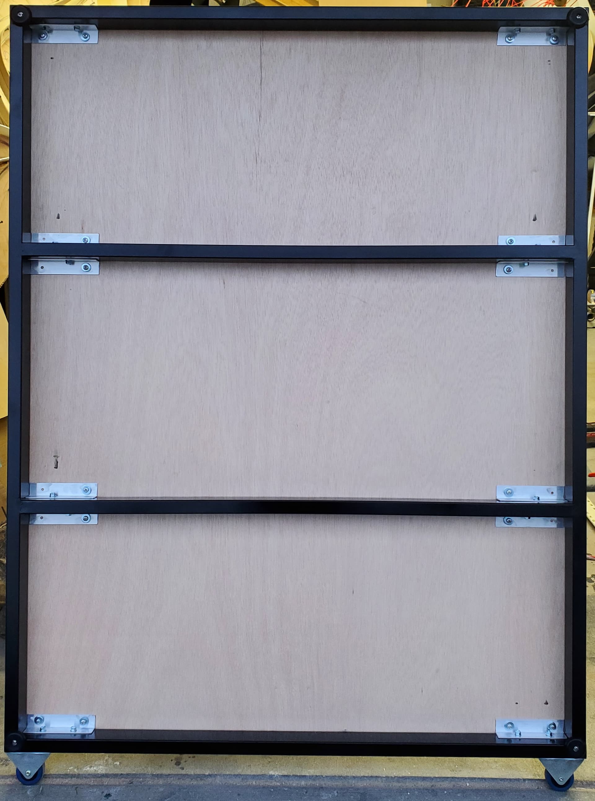
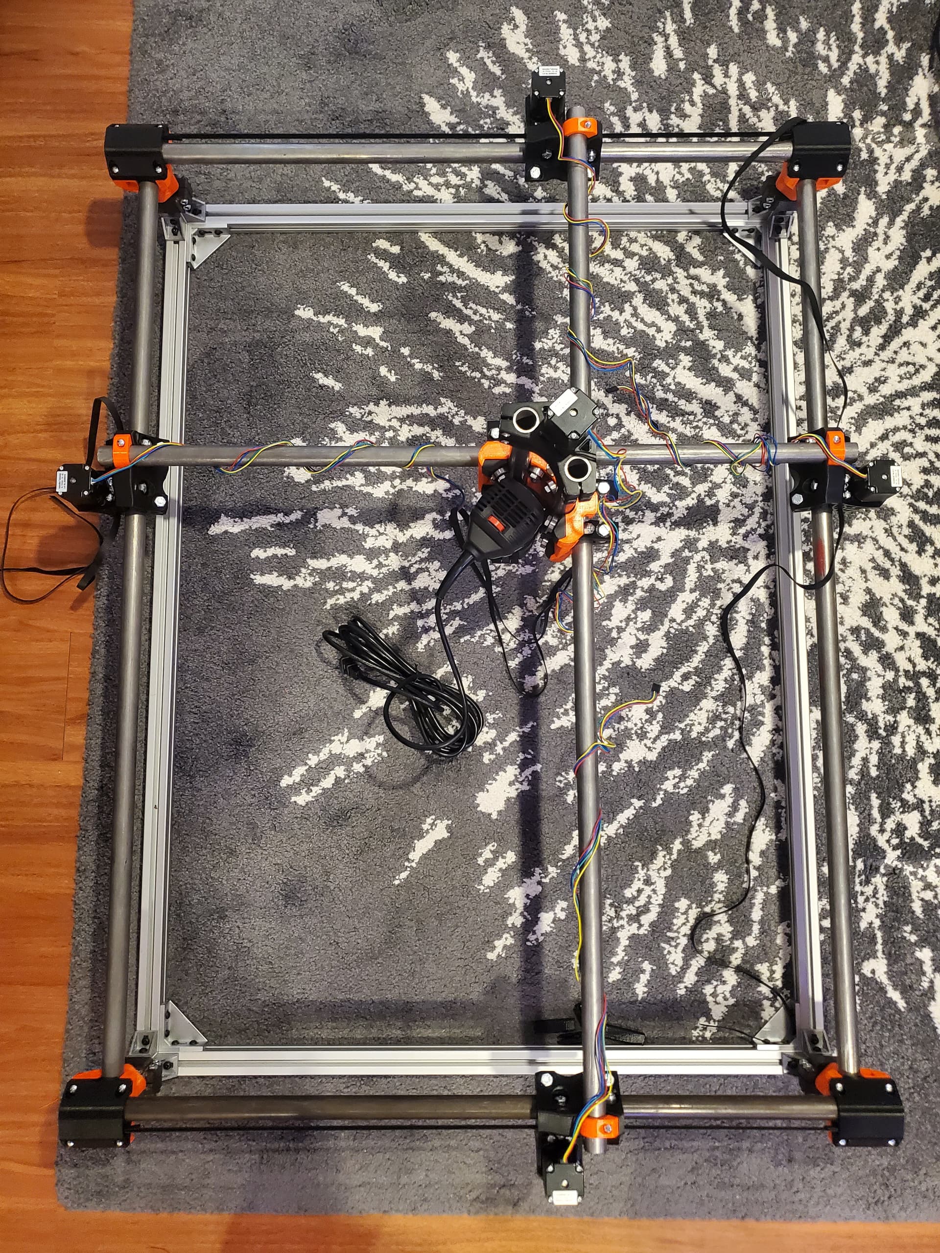
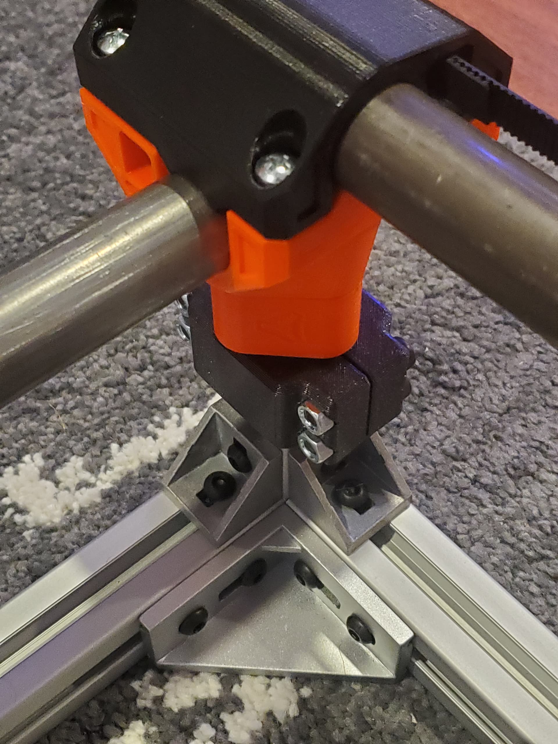
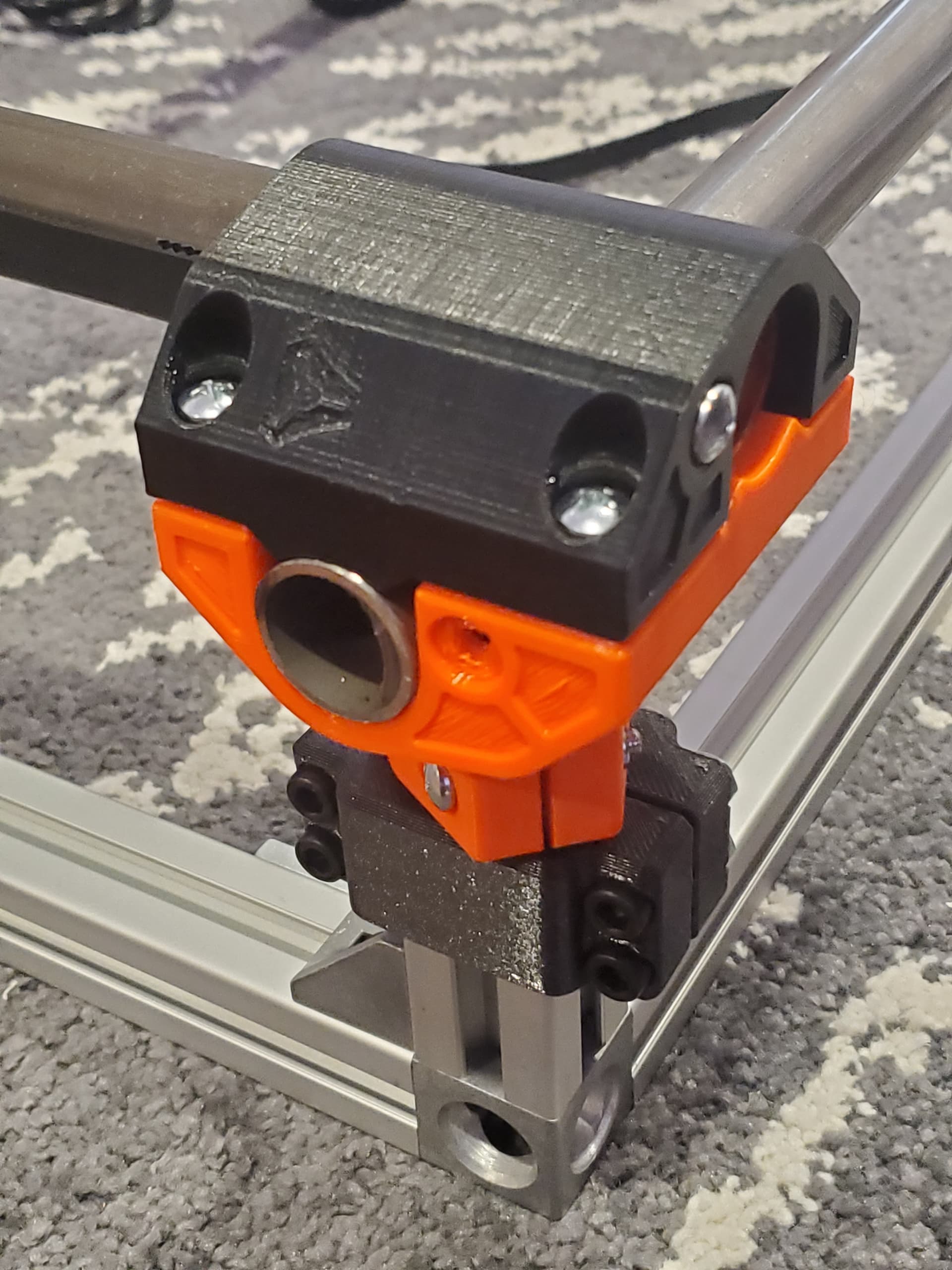
Finally got around to start building my Primo this week, after almost a year of no progress. I live in an apartment but will be operating my Primo elsewhere so I knew I had to make it as portable as possible so it can be transported back and forth between locations. For this reason I decided to build a base frame out of 3030 aluminum extrusions like some others have done. Benefits are increased rigidity for transport as well as ease of assembly because there is no need to accurately cut the 4 legs to the same exact length or screw down the feet in the exact right spot.

All my parts are printed in PETG, I spent a little extra on filament because I wanted the Primo to match my Prusa and of course my core print failed at 85% :laughing:

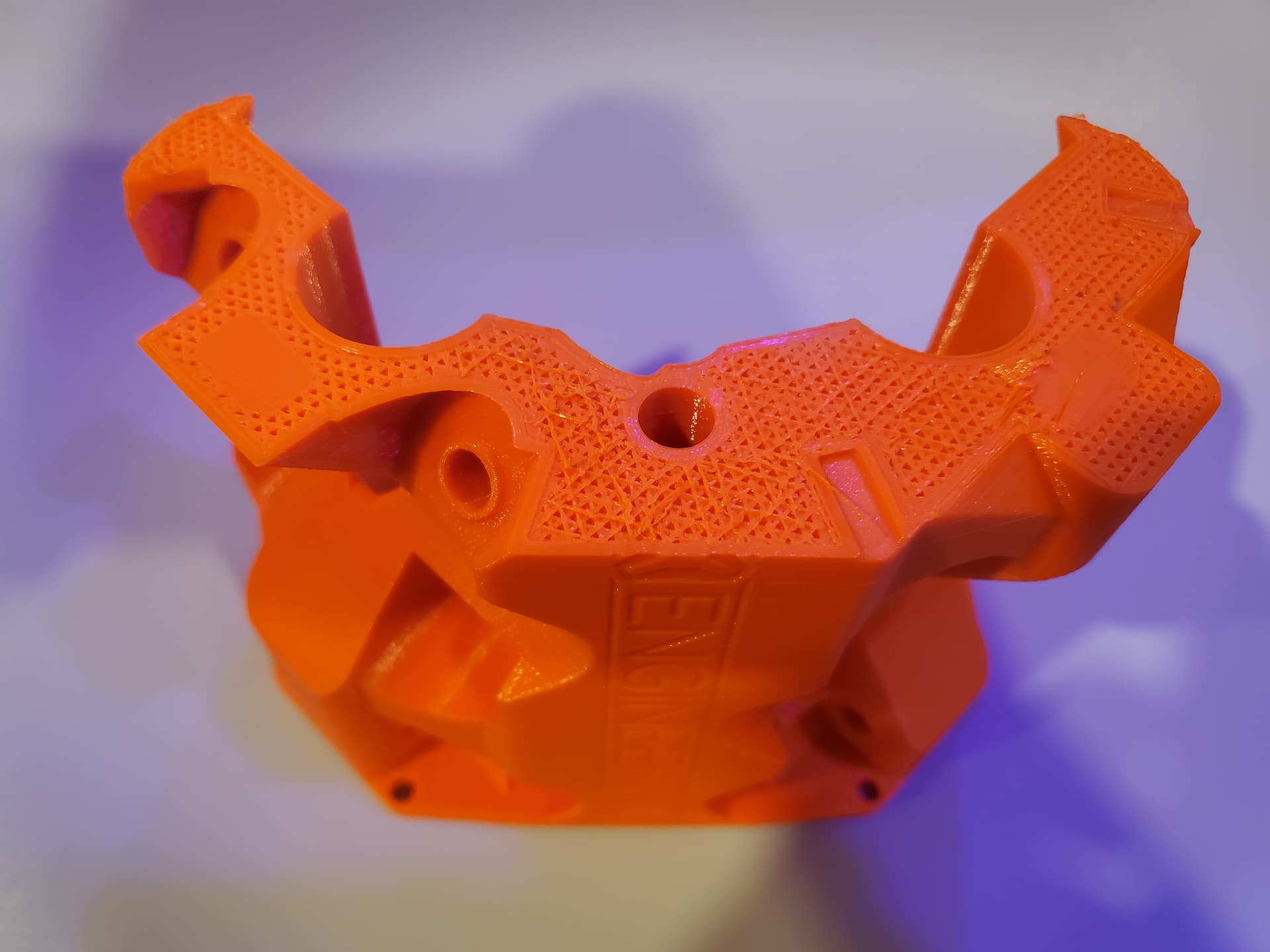
The reason for the failure is that the orange PM brand (Prusaā€™s old supplier) filament was wound too well around itā€™s spool and would unwind itself slowly until the loose filament got caught on my skate bearing spool holder. When I was new to printing I thought the skate bearing spool holder was a good idea but in practice a basic spool holder is best, the small amount of friction is necessary to keep it from unraveling. I ended up having to buy a spool of orange Prusament to reprint and it was also wound too well. Learn from my mistake and keep it simple!

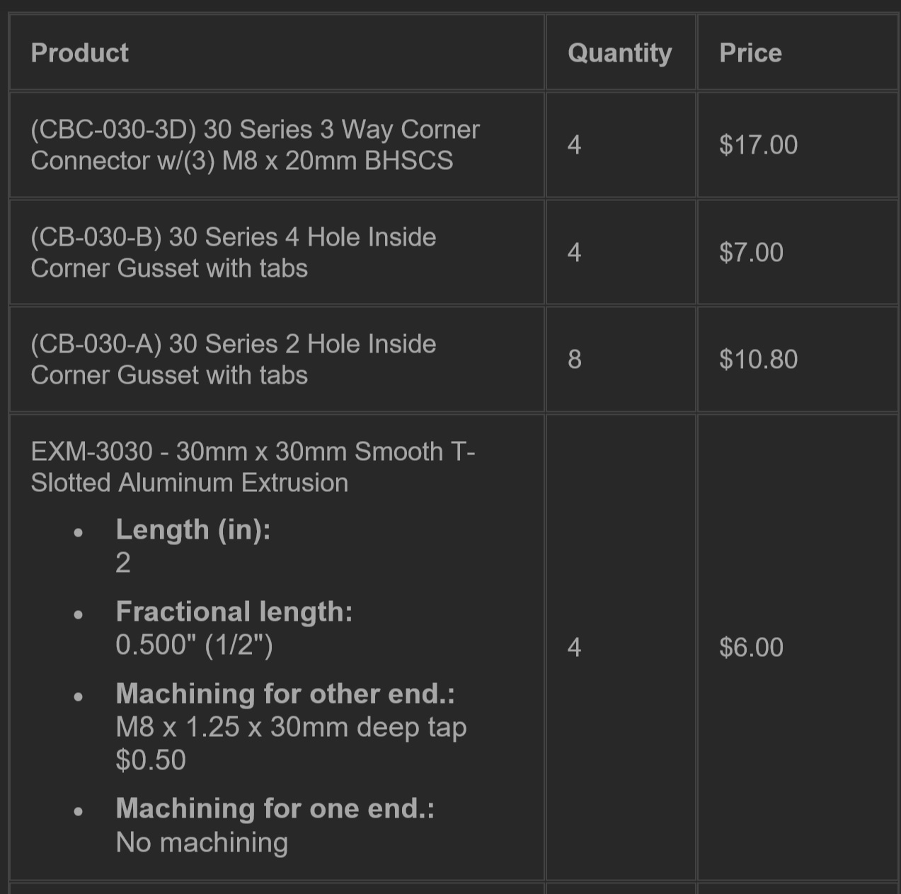
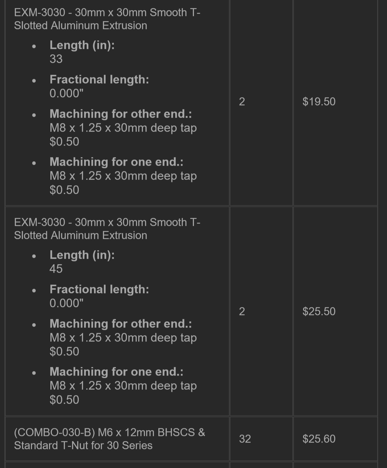
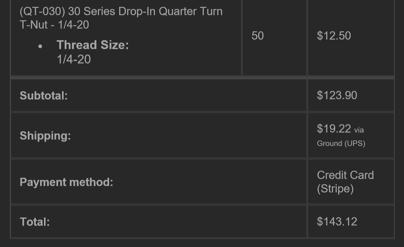
Sourcing the extrusions at a reasonable price is the main reason my build was delayed, besides laziness, of course :sweat_smile:. I scoured the net and after much wasted time building out carts on various sites I learned out about tnutz.com on a Sprinter van conversion forum. Sourcing the cut-to-spec extrusions and fasteners/hardware from them was wayyyyyyyy cheaper than the more well known alternatives like 8020.net and much faster, no waiting on a four week lead time. Here is the invoice of what I ordered from tnutz for $143.12 total:

See my previous post for where I sourced my DOM tubing at the best possible price: Where to buy D.O.M tubing? / PETG parts

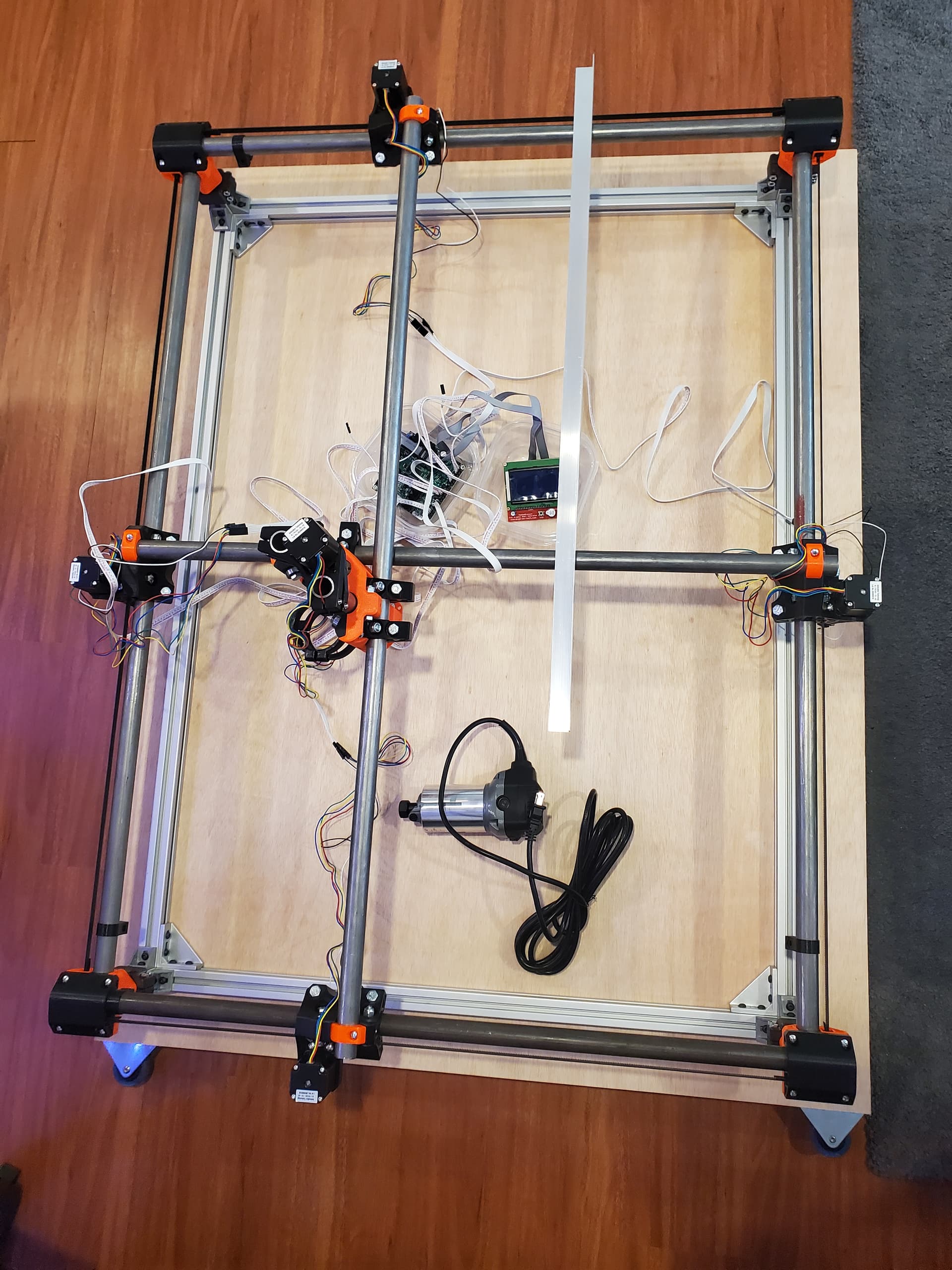
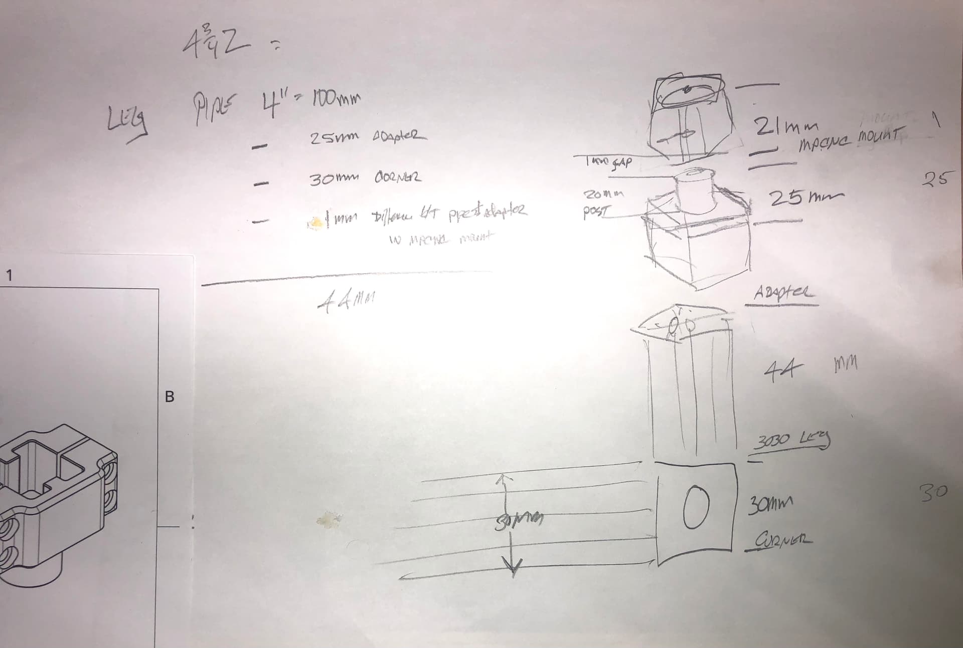
Figuring out what lengths of extrusion to order was a bit confusing for me, I ended up ordering based on the table dimensions on the calculator, the outer dimensions of the feet. The result of this is that my build area is now slightly larger than 24in x 36in because the stock Primo feet are wider than the 30mm extrusion. The outer measurement of my extrusion base is 35.4in x 47.4in.

Even reviewing my notes now Iā€™m not exactly sure how I arrived at these dimensions, luckily when I ordered the DOM tubing I ordered extra length on each cut. Not only were the cuts not very accurate or clean, but I was able to have enough extra length to make up for the new slightly larger dimensions. Only the x rails ended up being a few mm short. Additionally, it should be noted that tnutz only allows you to order cuts in specific fractional increments, another reason I ordered my extrusions up to a round inch (add 60mm for two 30mm corner connectors), 8020.net allows cuts down to the mm.

I think I speak for everyone, mixing Imperial and Metric in projects is so infuriating! :angry:

I whipped up a simple jig for drilling the holes in the z-tubes (25.4in), itā€™s not actually very good for keeping the drill bit in place, but it is a quick and easy way to mark the holes on the tubes. I tried drilling my holes with a 5/16th (8mm) 135 deg drill bit without a center punch and they ended up a little wonky but I had no issues with assembly.

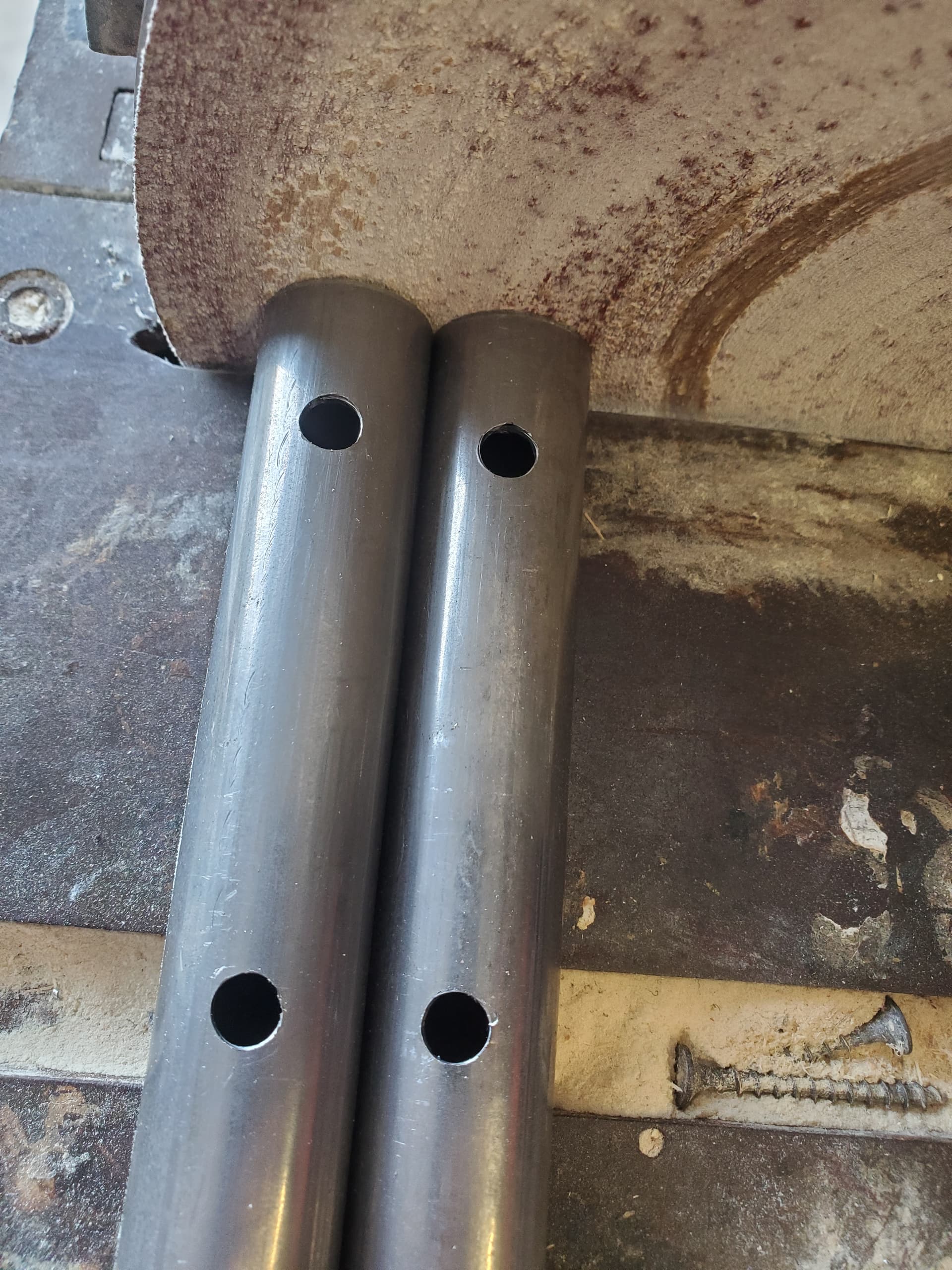
The only cuts I had to make were on these tubes, I used a tubing cutter which leaves a raised inner lip in the profile of the cutting wheel so I carefully removed that on the sanding disk before using the jig. You can download the stl here: PrusaPrinters

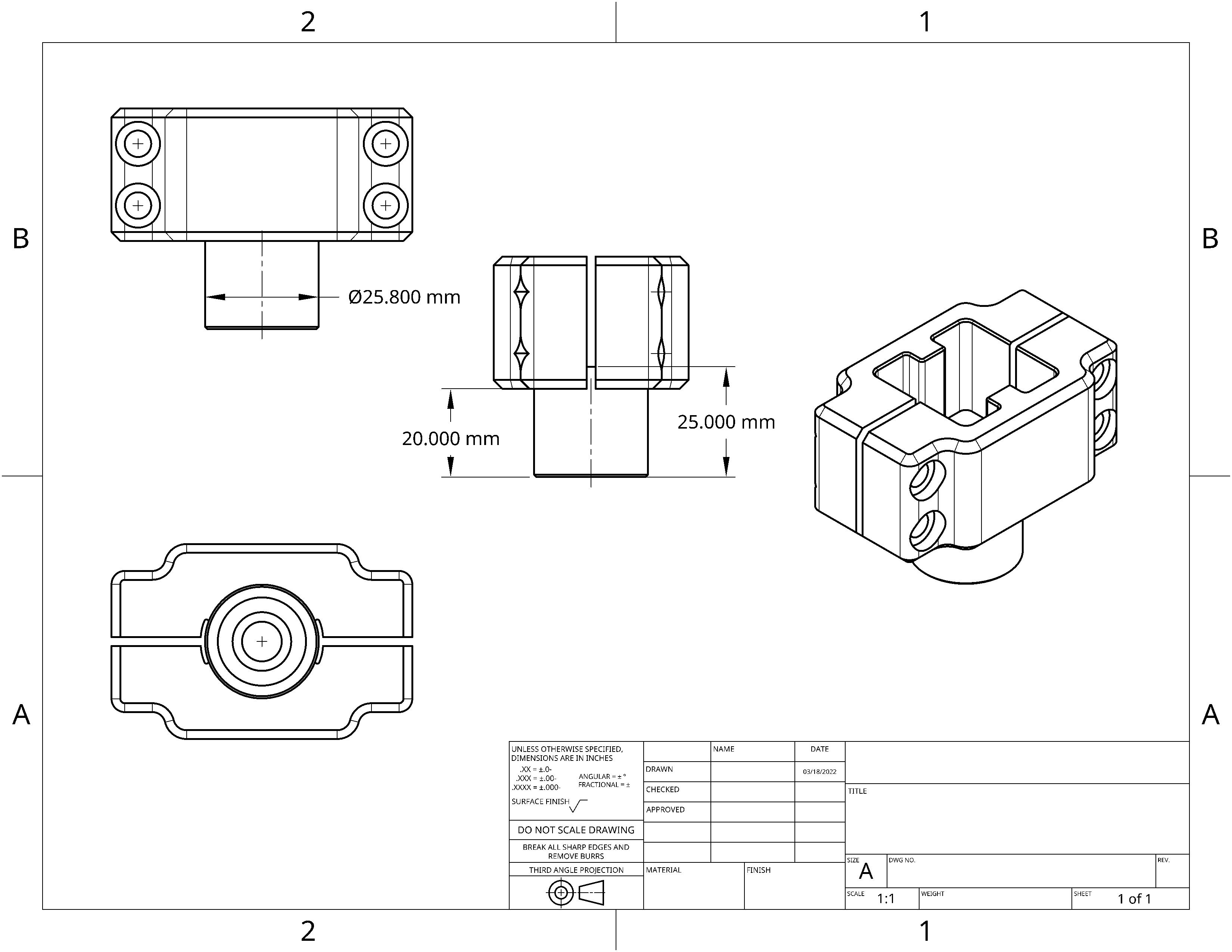
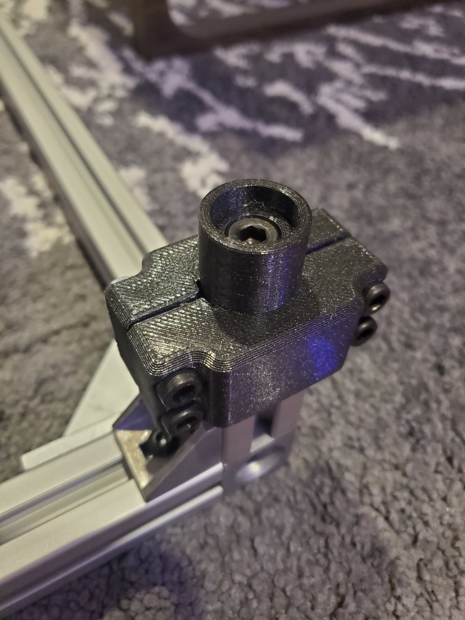
Adaptor for 3030 Aluminum Extrusion


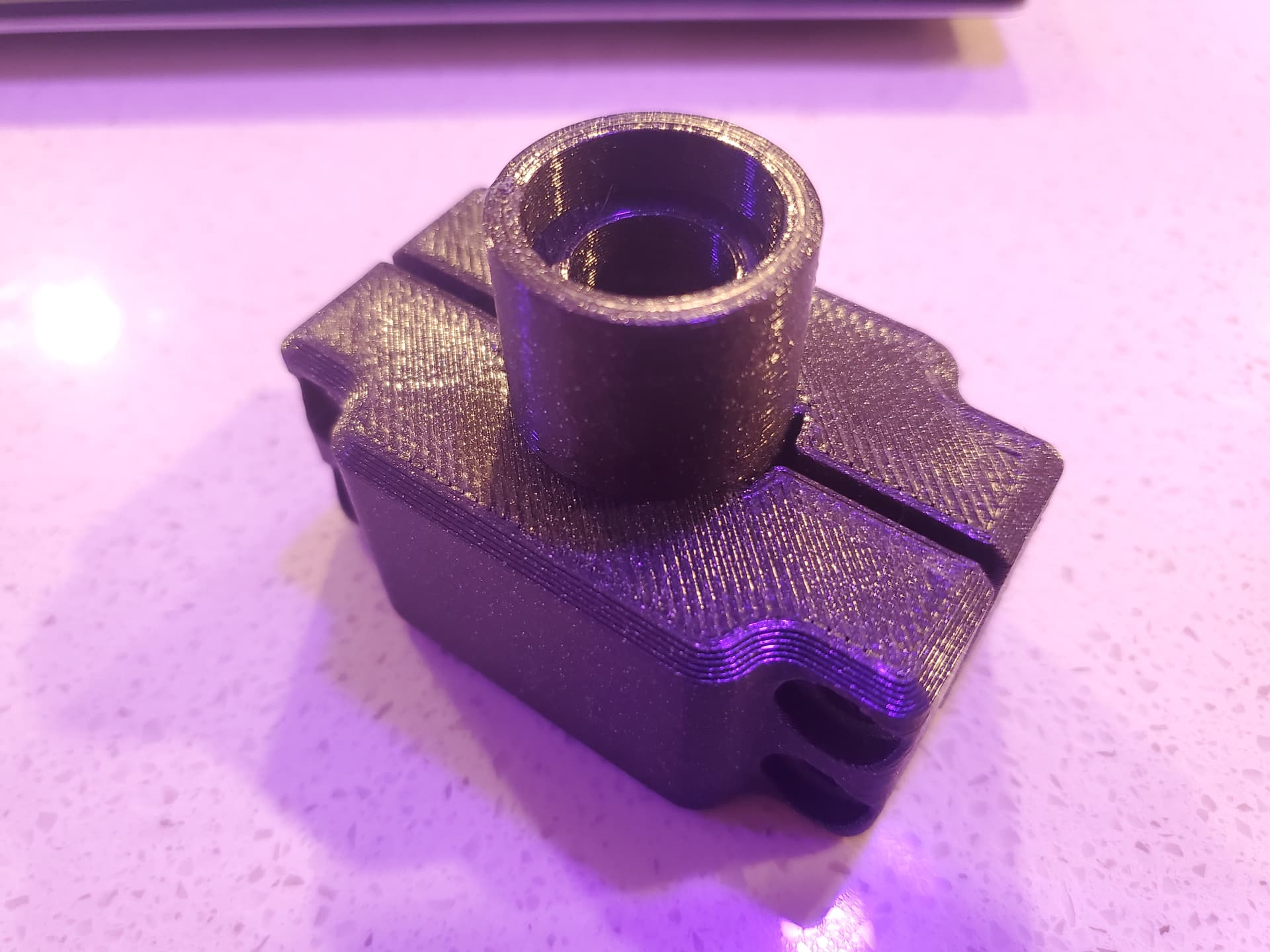
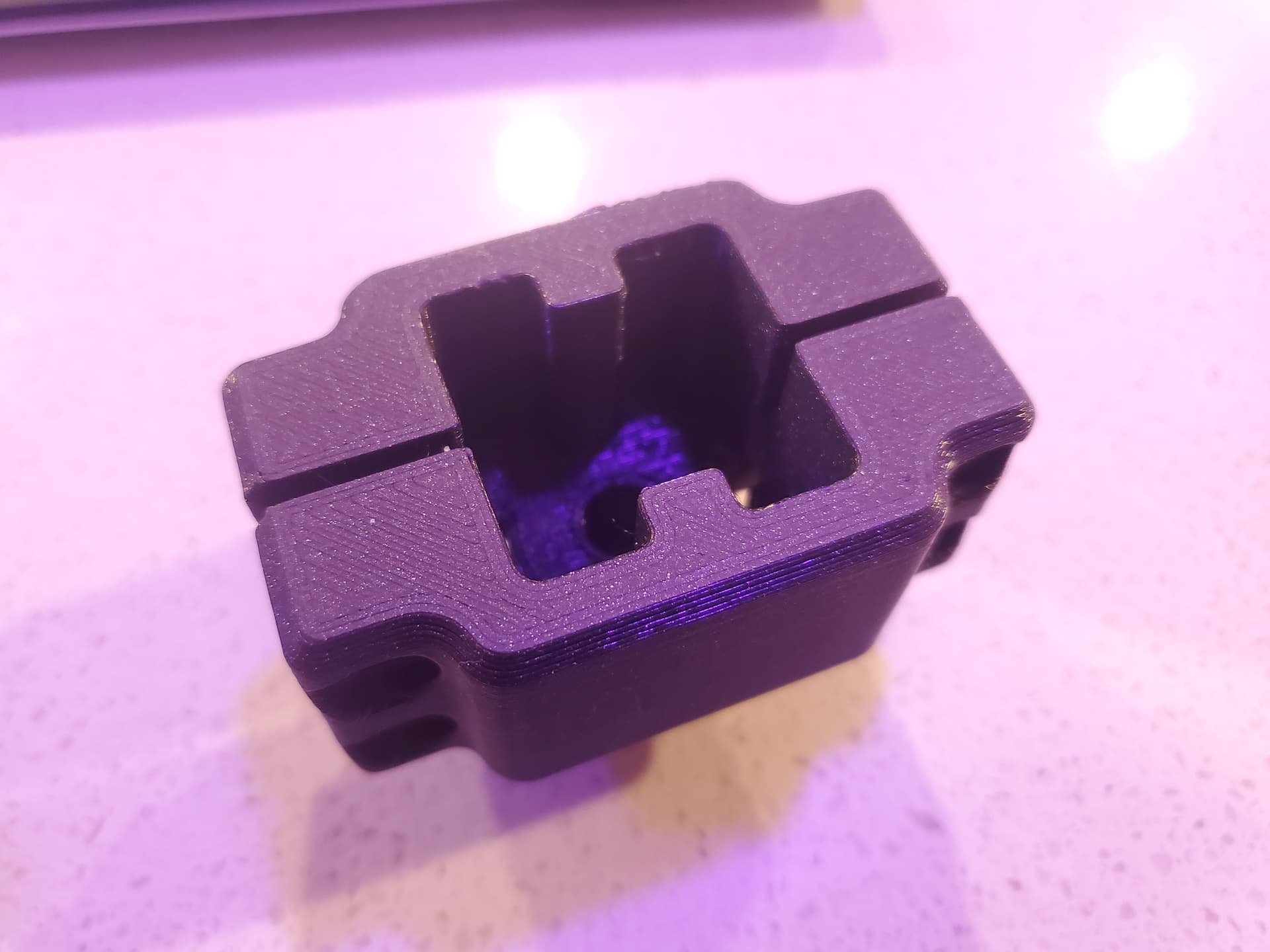
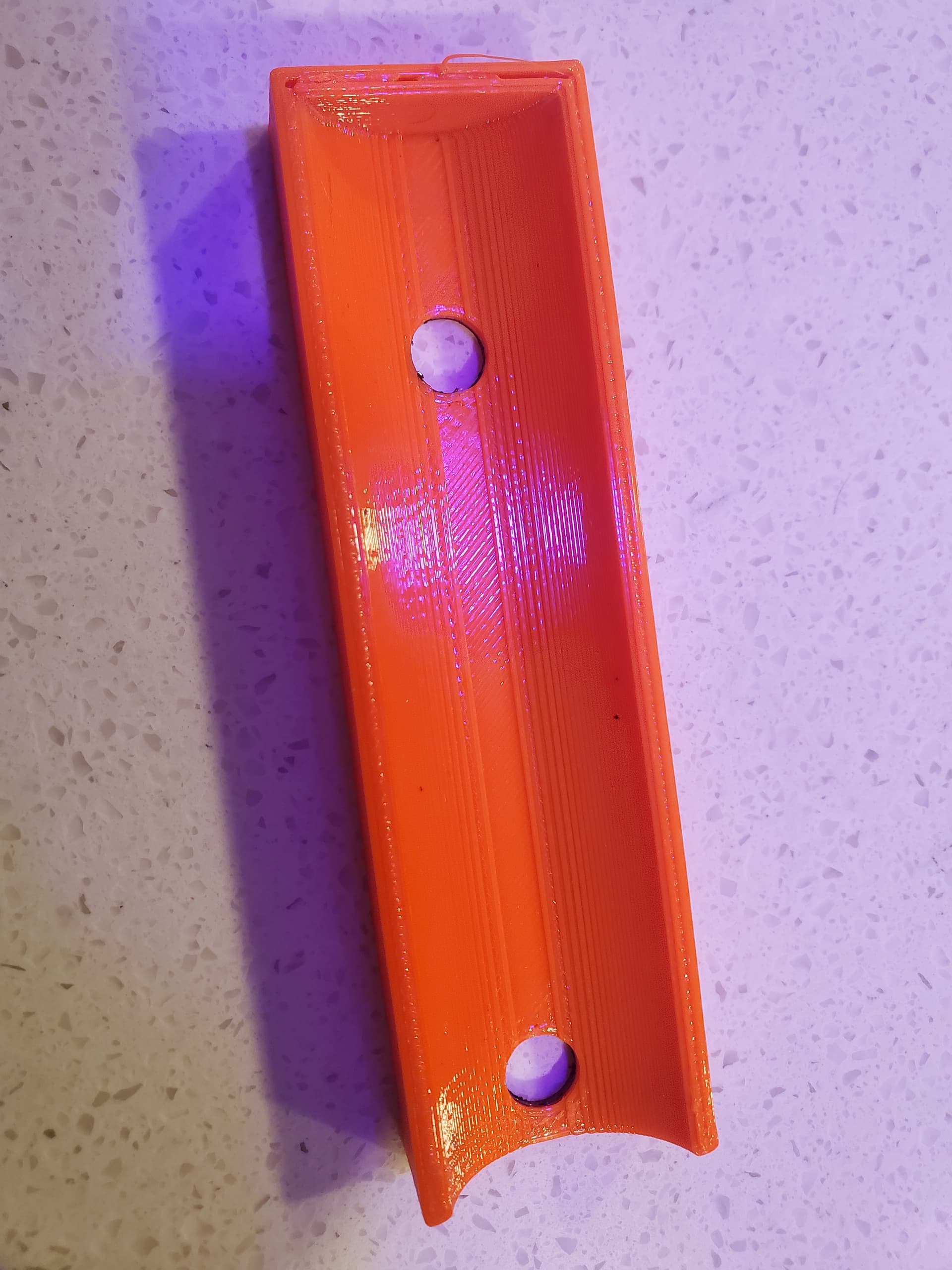
There were a few adaptors floating around on the forum already but none of them were skookum enough for me :laughing:. I designed this adaptor for the 3030 legs so that the connection would be as strong as possible and I could assemble the rest of the Primo as normal. The part is designed to slide on the extrusion with no slop and uses four 6mm hex bolts to clamp down hard on the profile. Hard enough to make Ryan cringe! The hole on top takes an 8mm hex bolt and threads into the tapped extrusion, I think you could get away without this bolt if you had to, the clamping force from the other bolts is so strong I couldnā€™t pull it off with all my strength. You can download the stl here: PrusaPrinters

Next, I need to get the wiring figured out, Iā€™m a little bit lost, there are no detailed instructions I could find on how to wire it up. I have a RAMBo v1.4 board and all the wiring that came with the Primo kit. I donā€™t remember ordering the endstop switches, but they are in the kit. I think I need to add the endstops to my build because I never got my gantries squared to within that 1mm threshold, but close. The endstops would help the steppers compensate for this? The whole squaring process was a bit confusing and frustrating, I may have to disassemble and redo that later.

I still need to read up more on the wiring but if anyone can point me in the right direction it would be appreciated!

6 Likes

Back when you ordered your rig, serial/series wiring was the default, and you cannot do dual endstops with serial/series wiring.

I donā€™t remember ordering the endstop switches, but they are in the kit.

The switches and their wires came with your Rambo board. They are not something V1 selected as part of your kit, so it is still likely you have a serial/series kit. If you decide to go dual endstops, and you need to order wires, I am impressed with Ryanā€™s wiring kit for dual endstops, but you can order stepper wires off amazon. You need 5 cables. Ryanā€™s wires are 6-pin, but the ones on amazon are 4-pin, so if you order from Amazon or the like, you will also need some extension cables or some extra wire and solder for the endstops.

The wiring itself is pretty simple. For serial/series, you just have two ā€˜Yā€™ harness wires for the X and Y axes. Each arm of the ā€˜Yā€™ plugs into a stepper and the leg plugs into the appropriately labeled plug on the control board. All the issues concern how to run the wires given they will be moving. Cable chains, sleeves, and sleeves using the tape measure trick are popular. Also consider where you run the wires with respect to how you will be using your machine.


Please keeps us updated on how the aluminum extrusions work out.

2 Likes

Thanks for the info! I ordered the wiring kit to add the end stops to my build. Cant go wrong for $15

I am going to go with drag chains laying on aluminum angle. I saw that in many builds they are putting the wires in sleeves inside of the drag chain for extra protection?

I was considering buying more extrusion to cross the empty space in the 3030 frame and mounting a sheet of 3/4 plywood to that. This would reduce my z by the thickness of the plywood and the 3030. As it is right now I have about 5 inches of vertical build area with the z fully raised. I would be left with about 3 inches vertical. This would be better for reducing deflection while milling I would assume.

The other day I attempted to weld a table top frame (no legs) out of rectangular steel tubing that would take a sheet of plywood as itā€™s surface but it ended up very distorted, I donā€™t have a flat surface to fixture to for welding something this big. I am going to try again this weekend, I donā€™t want the distorted surface to telegraph into the machine. I need something to mount wheels to and to allow me to store the Primo on its side. I had planned to mount these directly to the 3030 but I think transporting it this way would be too rough on the machine. It would be nice to have the waste board be flush with the top of the 3030 because I plan to cut oversized materials.

I saw that in many builds they are putting the wires in sleeves inside of the drag chain for extra protection?

I donā€™t think this commonā€¦or necessary. I did use some sleeving on the exposed wires leading up to and exiting the cable chains.

I was considering buying more extrusion to cross the empty space in the 3030 frame and mounting a sheet of 3/4 plywood to that.

Iā€™ve never constructed anything from aluminum extrusions. At one time, I mused about building a portable MPCNC, and I thought about extrusions for that build. In my design, I had many crossing extrusions, and I had slots in the spoil board that matched these crossing extrusions. These slots combined with nuts in the tracks would be used as a clamping system.

1 Like

What Iā€™ve seen some folks do is run aluminum t-track in one direction, then fill in the spaces between the channels with spoil board material, like 3/4" MDF. This makes it easy to clamp in the track, the MDF has enough height that it can be resurfaced a couple of times before the track is flush, and new slices of MDF can be added whenever things get to thin.
Like this -
image
Or this -
image

1 Like

Awesome ideaā€¦ and the timing couldnā€™t have been better. I was trying to decide how to build this because I wanted my torsion box table to be used to set the MPCNC on as well as my Laser Cutter. being able to have the CNC a benchtop tool is great.

I have downloaded the adapters. I too use Tnutz for most of my extruded needs. I am building the Primo as well.

I was also thinking of using more 3030 for cross members for more support to then attach a spoil board to the 3030 frame so it can be moved as one complete unit, would it be advisable to maybe add the thickness of the spoil board to the length of the 3030 legs?

4 Likes

I think I answered my own question by looking at your order list from Tnutzā€¦ the legs were ordered at the stock height of 2.5" as the calculator specs out for 3.25" Z. Its amazing what happens when one reads LOL Still a great adaptation for those of us that want to ā€˜move aroundā€™

I ordered the dual endstop wiring kit, kind of seems like a no brainer for $15 since it will help compensate for any out of squareness on the the xy. Iā€™m a little scared of plugging them in backwards on the RAMBo and frying it.

There are a few builds on the forum where they do just that, but I think the t-track or nut inserts are probably just as useful? Much more inexpensive anyway. My Primo in Multi-Colour, Multi-Material on a Alu-Frame 30x30 B-Type Nut 8

The 3030 frame definitely makes the machine more mobile but the torsional rigidity isnā€™t amazing. It would probably be fine to transport this way if you are somewhat careful, at least in your case if you only have to move it to another room. Itā€™s stiff, but I can lift one corner about half an inch before all the flex happens and the other corners lift. I wonder if it would be noticeably stiffer with PLA parts?

Even this portable table top I welded has a little bit of flex if lifted from one corner. Itā€™s made of 1 inch by 2 inch 1/16th wall rectangular tubing with a 1/2 inch plywood top. Iā€™m going to bolt the Primo to it a least at the for corners. I tried to save money by not using 3/4 inch plywood but ended up having to buy a lot of washers at Home Depot to keep the screws from poking through the top.

I ordered some wire sheathing, it was $10 for a 15 foot roll and I think I am going to try and 3d print the drag chains to save money. The cost of my build is North of $1k at this point.

Here is the cost of my Primo so far, about $1100:

Primo kit: $378
Touch plate, endstop wiring, endmills: $54
Plywood: ~$65
DOM Tubing: $118.65
T-nutz 3030 extrusion, fasteners, connectors: $143.12
Filament and fasteners for 3030 to MPCNC adaptor parts: ~$30
Filament for Primo parts (including extra roll due to fail): ~$80
8 foot aluminum 1" x 1" angle: ~$12
Carbide 3d Makita clone with collets: ~$85
Harbor Freight wheels: ~$5
Various fasteners: ~$20
Wire sheathing: ~$10
Steel for base: Already had, probably $50 - 100

I was kind of just guessing when I ordered 2.5", I think with my adaptor that adds up to 3.7" legs or 4.85" if you account for the height of the 3030 frame. I really need to build up the waste board closer to the z axis, I might just do that by stacking plywood or 3d printing spacers. I think I saw a post where Ryan said he likes to use that pink insulation as a spacer for the waste board.

Iā€™m planning making a lightweight and easy to disassemble enclosure out of coroplast walls attached to EMT conduit and 3d printed connectors. Maybe I can adhere some sort of foam to the coroplast to try and absorb some noise.

You may be able to get an ā€œorigamiā€ enclosure just with the coroplast and strategic folding, without need for EMT. Check out Oru Kayak for inspiration.

Pressed paper egg crates are good at breaking up and absorbing some sound - low rent way to manage echoes in a ā€œliveā€ room. This foam also does a good job, but feels pricey to me, and I donā€™t know if it would lose it absorption as the pores fill with sawdust.

Iā€™ll recalculate the height of the 3030 legs taking into account for the perimeter frame. My mobile workbench will look something like this once the t-track is installed.

So Iā€™ll be able to clamp the frame onto the torsion-box based bench top. The spoil board will also have t-tracks and will also clamp onto the bench top inside the 3030 frame. My Z setup was for 4-3/4ā€ so the pipe legs needed to be 4ā€ā€¦ so i guess Iā€™ll order the 4ā€ 3030 legs less the height of your adapter less the thickness of the spoil boardā€¦ that should get me to where I need. Spoil board will be 3/4ā€ thick so the t-tracks sit well below the surface hoping they do not get hit by the router bit. Itā€™s costly with all the T-track but i will be using this Mobil cabinet workbench top for other applications in addition to holding the CNC router.

In a feeble attempt to draw what I am sayingā€¦ LOL

1 Like

I was thinking of doing some sort of folding design, not sure if I could engineer something like that to be presentable though. I almost ordered some of that foam, the bad ratings always turn me off. Not just sawdust but aluminum slivers! I wonder if the coroplast alone will result in any tangible reduction in noiseā€¦or will they make it worse by vibrating like a speaker cone?

Hereā€™s a drawing showing the 25mm that the adaptor will add to whatever you size the legs. I donā€™t remember how deep the ā€œCorner Topā€ part is but this only slides in 20mm, itā€™s close but I think I left some vertical space so that could add another few millimeters to the length if that makes sense. I made sure to use a sharp razor blade to remove that little ā€œnubā€ left over from when the printer finishes printing just in case.

I also had to buy 4 shorter M5 bolts for the corner tops so they wouldnā€™t be long enough to hit the top of the M8 bolt in the adaptor.

I oversized the ā€œtubeā€ part to 25.8mm to make it tighter, Iā€™m sure the actual printed dimensions will vary from printer to printer.

Wont your spoil board be 10mm below the top surface of the 3030 frame if you clamp it to the bench top? Do you want that extra height? I am looking at my spoilboard at least being level with the 3030 frame or higher so I can fit oversized plywood.

According to the calculator, my DOM legs needed to be 4ā€ for 4.75ā€ Z. I will make my spoil board >= 30mm so its flush or nearest mm proud of the height of the 3030 so we can slip longer pieces if necessary. 4ā€ is 100mm, less the adapter of 25mm so Im thinking I need to order 75mm legs giving me a total of 100mm from the top of the 3030 frame to top of Z work area. did I miss anything? LOL

The only thing missing is that we donā€™t know the true depth of the Primo corner part. I measured it with calipers when designing the part but I canā€™t remember now. So the adaptor sticks in that part 20mm but maybe its 25mm deep? Wouldnā€™t that effect the calculator numbers?

Loaded the dual endstop firmware and plotted my first crowns!


5 Likes

If you use a bit of a flex mount for that pen it will absorb the minor deviations in your table and those will be perfect crowns.

Ok, here is what I came up withā€¦

The 3030 corner is 30mm,
Your adapter is 25mm in length with 20mm inserting into the MPCNC top of leg mount, which is 21mm deep. So, at 100mm for 4ā€ pipe leg requirement, subtracting the 1mm, 25mm, 30mm from the 100mm, leaves 3030 extruded leg of 44mm. I will likely just order a single piece and cut myself with jig to insure that if they are not exactly 44mm, they will be exactly the same regardless.

Iā€™m sure there are those who know more, but how significant is the exact accuracy of the height of the leg? Will 1mm really make a difference in anything meaningful? I wouldnā€™t think so but hey, i know little about this CNC stuff.

I just realized my mistake (or one of them lol). I need NOT deduct the 30mm of the corner bracket since my spoil board will sit just above flush to the 3030 parameter frame. DOH! almost ordered too short of legs. After recalculating, I am confident that one need only subtract 26mm from whatever the V1 calculator specs out for leg length if the spoil board will sit at or just above 30mm parameter frame.

Hey, Iā€™m in Vancouver, WA. Assuming your post means Pacific North West? could you tell me your approximate build cost?

I almost made that mistake too. Your diagram looks right to me, I think the leg height isnā€™t critical down to the mm. I assume the min leg length is due to the height of the stock Primo 3D printed foot and two corner pieces. I think you could go as short as the inside height of the 3030 adaptor if you wanted, I could be wrong. Unless you need the extra room for something thick no need to have 4" legs, but it doesnā€™t matter anyway. You can put a temporary spoil board below the 3030 if you needed to mill something thicker.

If you didnā€™t already order the extrusions today I would recommend letting Tnutz do the cutting and tapping. Their cuts were perfect. If you look at my invoice I actually didnā€™t pay for both ends of the short leg pieces to be tapped for 8mm but they did anyway and Iā€™m glad they did because I ended up adding the 8mm bolt to the adaptor. Just order to the nearest fractional inch to your intended leg length when you order from them since they donā€™t cut to mm, I donā€™t think the leg length is that critical.

Yes, Pacific North West. My build is going to end up around $1200. If you scroll up a bit I have a breakdown of the costs. I just purchased some drag chain (~$50), more aluminum angle and some fasteners (~$20) and I have some more custom wire management stuff to print which will probably cost another $10 in filament.

I would say that the cost of my build is easily inflated by $300 just because of that extra foot on the y-axis, 24" x 36" vs 24" x 24"

I donā€™t think $600 is a realistic budget for most builds unless you build it really small and basic and screw it to a scrap of plywood you already had. Not that I am complaining or saying it canā€™t be done.

Thank you for your response!

1 Like

Hi - just stumbled upon this post as I was looking at Tnutz (Iā€™ve used them before) to find out if they specify a precision/tolerance. The web form for ordering allows only fractional, and only down to 0.125". However, from their FAQ:

[Can I order metric profile lengths?]

Yes, please buy the closest equivalent and in the buyer notes let us know the length in millimeters.

In addition, I just emailed support, and the guy said (he emailed me back in 5 minutes on a Saturday) that their saw can be set in increments of 0.004". Thatā€™s ~0.10mm.

Their website kinda sucks, but their quality, support and price are great.

1 Like