Hi all, first time MPCNC builder, first time poster here. I cannot get my gantry squared during step “7-Squaring”. I would appreciate any suggestions and help.
Background: So far everything in the build has gone very smoothly. Corners on the feet measured less than a millimeter on the diagonal, and almost indiscernible difference on the x and y lengths (which you must also measure otherwise you could get a trapezoid). The trucks went on well, they move slowly when tilted 45 degrees, and they squared very nicely following the instructions (I had to correct about 3mm). The core when together well with minor(?) exceptions. When I first put in the rails, one of them had a small wiggle between one set of bearings (no nuts on the outside bolt). I was very cautious not to over-tighten and the wiggle went away after slightly tightening the nuts between the clamp and core body. The only other (noticeable) exception was the rails slide more easily than the trucks, but they still have reasonable(?) resistance.
The Problem: While trying to square the gantry with the core attached to the rails, I get no movement when tightening or loosening the adjustment bolts.
Root Cause Analysis: I re-read the instructions and previous steps many times, and I don’t find any discrepancies in my methods or build. I went to the forums and found a couple similar posts. The closest problems were resolved by disassembling back to previous steps and redoing the process. I removed the core, verified my corners, loosened and re-squared the rails, everything up to this point matches. I put the core back on and see an immediate deviation of 5mm. The trucks closest to the origin (0,0) are too close to the origin, while the trucks on rails opposite the origin deviate away from the origin. In both dimensions this means I need to tighten the inner bolts. I started with all four bolts loose. VERY loose. Not even seated to the plastic with a visible gap. I tightened only the inner bolts starting at as 16th turn each, then moving the core in figure eights, and measure. No difference. Eventually the bolts become quite tight, and the tension on the gantry rails is so tight the core only moves haltingly. At this point I stop because it feels like any more and the clamps will be compromised. Still no deviation in the square measurements. I loosen the tension bolts and start over with the same result. Then I think maybe the tightness of bolts between the core and clamps may be wrong, so I try the above procedure again with them both quite a bit tighter and quite a bit lo0ser with the same results, actually the measurements are now permanently worse. I also tried loosening and tightening the gantry pipe clamps with no difference. Then I try resetting everything and adjusting the truck bolts instead of the gantry bolts. It seems to make a very small difference, but the trucks ride worse on the rails as a result, almost as if they are fighting against the core if that makes any sense.
Current State: I reset everything back to the original instructions, attached a pencil and drew a rectangle (parrallelagram). The sides are very nearly equal (around 0.5 millimeter, but the diagonals are off by a quarter inch. The difference between rails is about 5mm for both x and y.
Potentially useful information:
- I measure with calipers from the edge of the top corner to the edge of the truck.
- My core is printed in PETG (Accidentally bought it based on reviews for structural integrity, thinking I was getting PLA, so decided to just try it, and it’s stronger than my PLA parts.)
- Clamps are printed in PLA
- My PLA and PETG calibration prints are around 0.05mm per 50mm average, w/ variance around the same on the measurements.
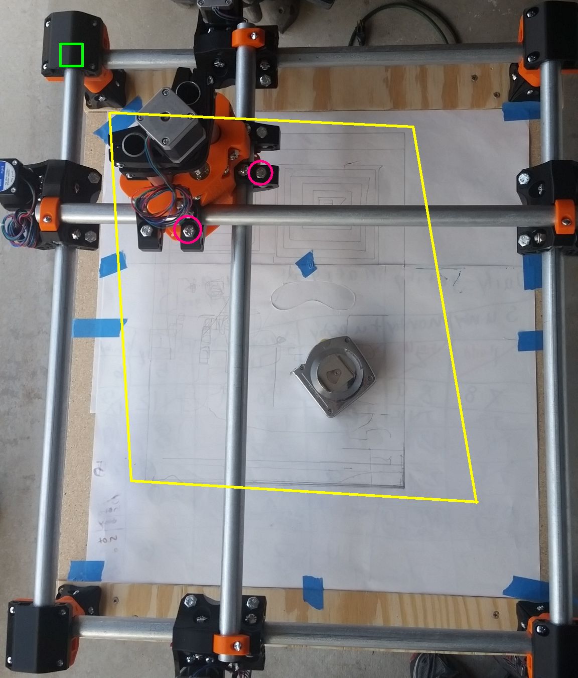
- In the photo, the yellow box exaggerate the deformation of my workspace. The green box shows the origin. The pink circles show the bolts I am tightening to try and square the gantry. The non-circled bolts on the core clamps I have tried loosening also. Please ignore all the extra scribbling. The extra lines in the area kitty-corner/diagonal/oblique to the origin are mostly due to variation caused by drawing the box without realizing the belts were causing issues.
- If possible I would like to avoid reprinting the core. I’m more apt to waste time modifying firmware and add calibration fudge factors.
- If possible I’d like to avoid speculation on what’s wrong.
Help is greatly appreciated.
 I am officially out of ideas. I am sorry.