Problem with Finger Joint Cuts

Hi, I’m having a problem with my Primo (610 x 460 x 81). I have a build thread (here) so I won’t go into all the details that are already in that thread.

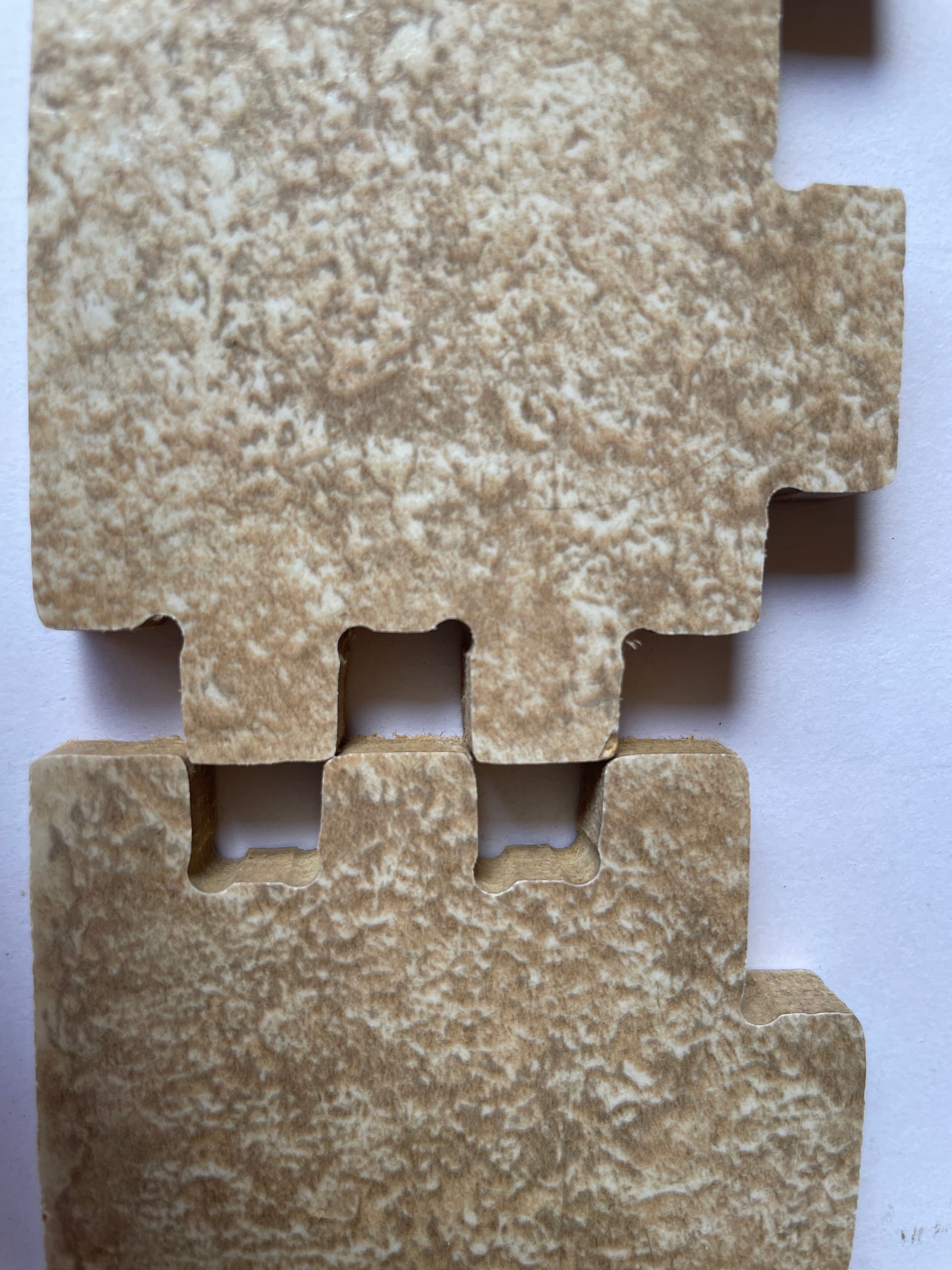
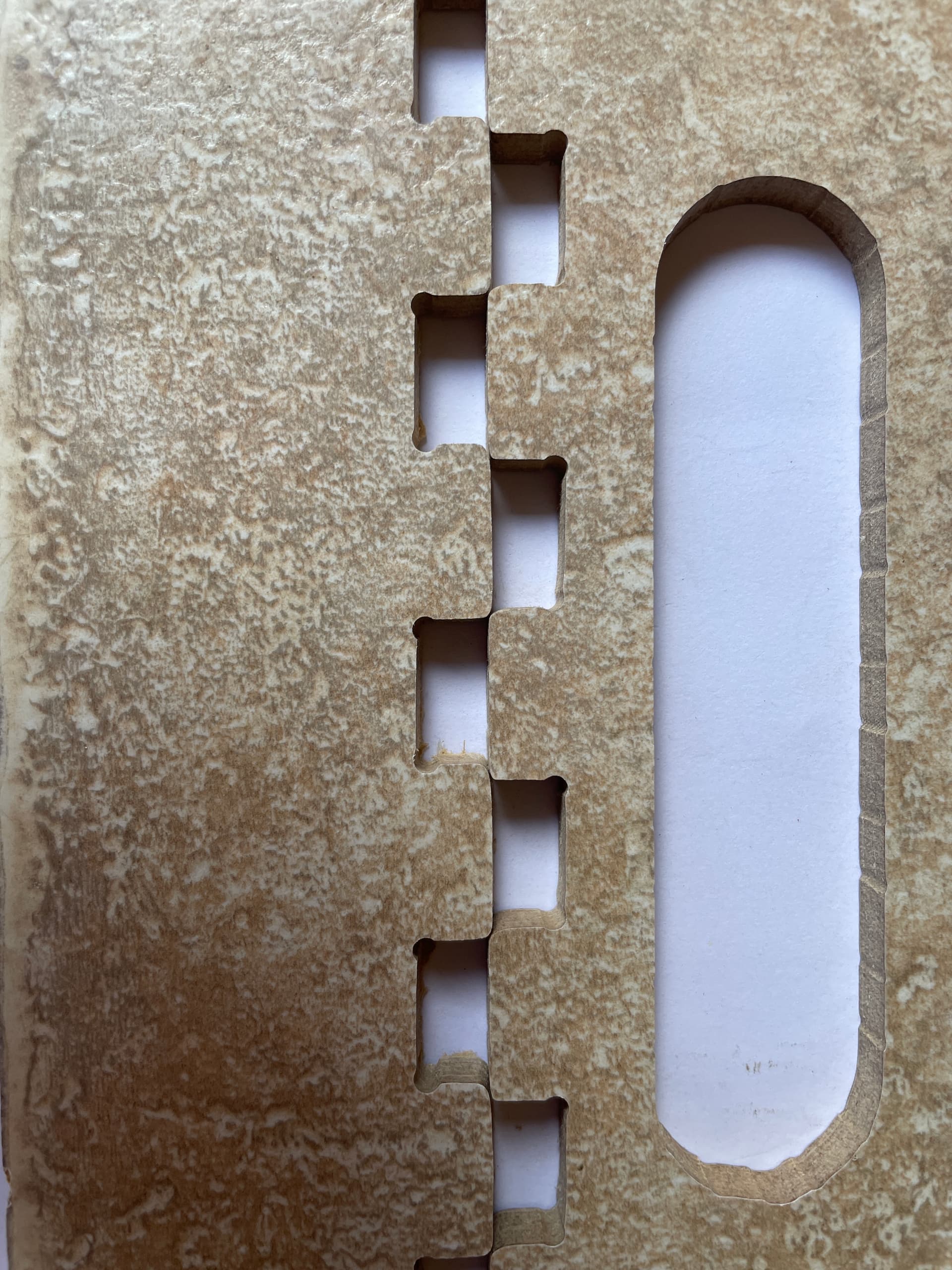
I am trying to make a tray measuring 380 x 380 x 60 using Fusion 360 with a couple of Add-Ins, namely FingerJoints and Dogbone. FingerJoints creates, strangely enough, finger joints for connecting the tray panels together. Dogbone creates the small cutout on the internal corners of the tab slots so that the tabs fit all the way in. These add-ins seem to work well in that they create the required features for my tray.

I have sized the tab slots to be 0.2 mm wider that the tabs themselves to allow an easier fit and make room for some glue.

I am using the Fusion 360 Manufacture module to define the cutting processes and have installed the flyfisher604 post processor. I have used the software to create a couple of other pieces that have cut OK. The machine axes are square. I penned a 280 x 400 (to fit A3 paper) rectangle, and the diagonals were well under a millimetre in difference. The sides of the rectangle were also square when measured with a square.

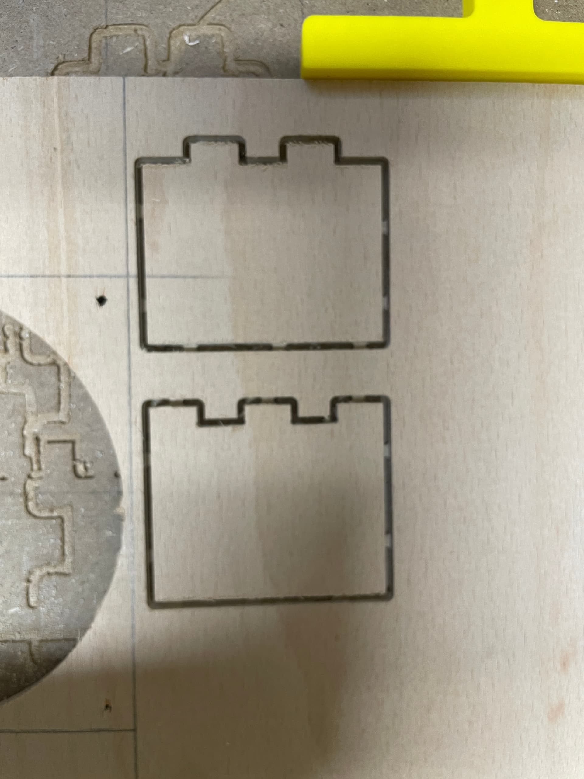
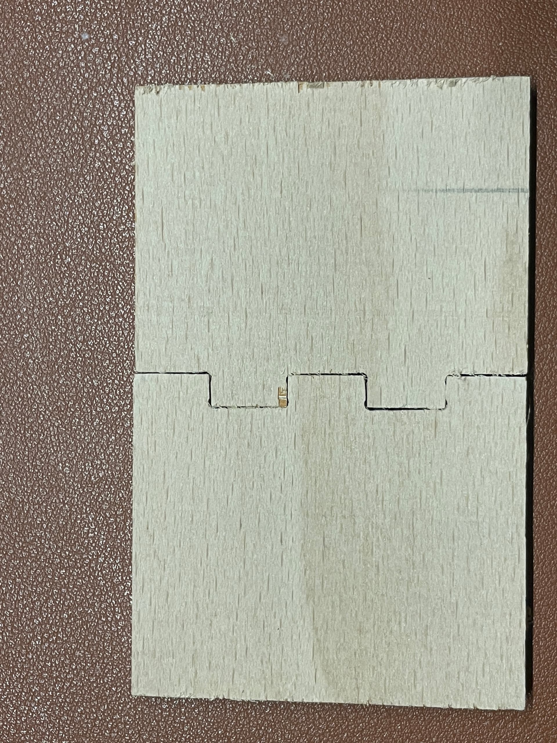
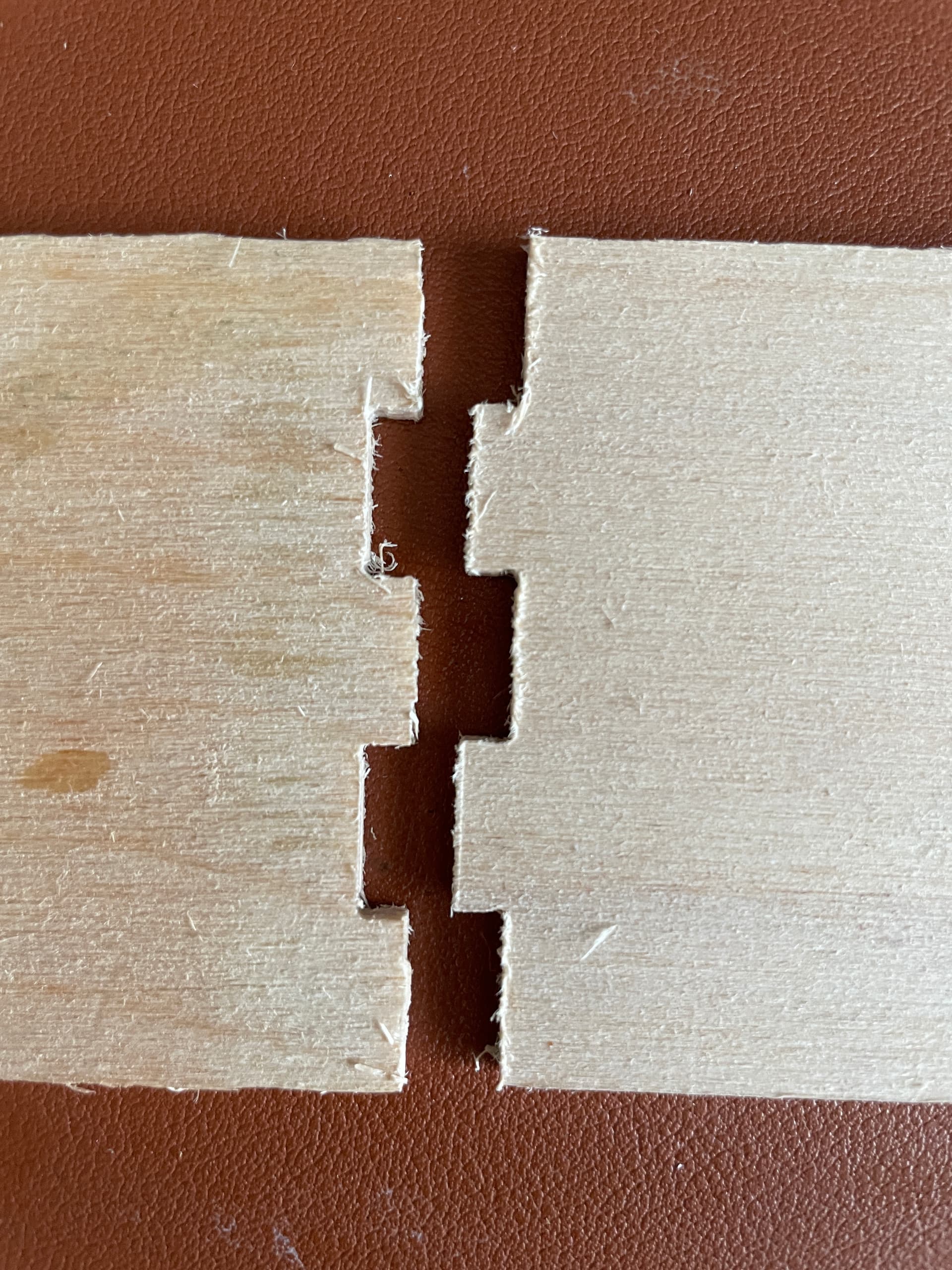
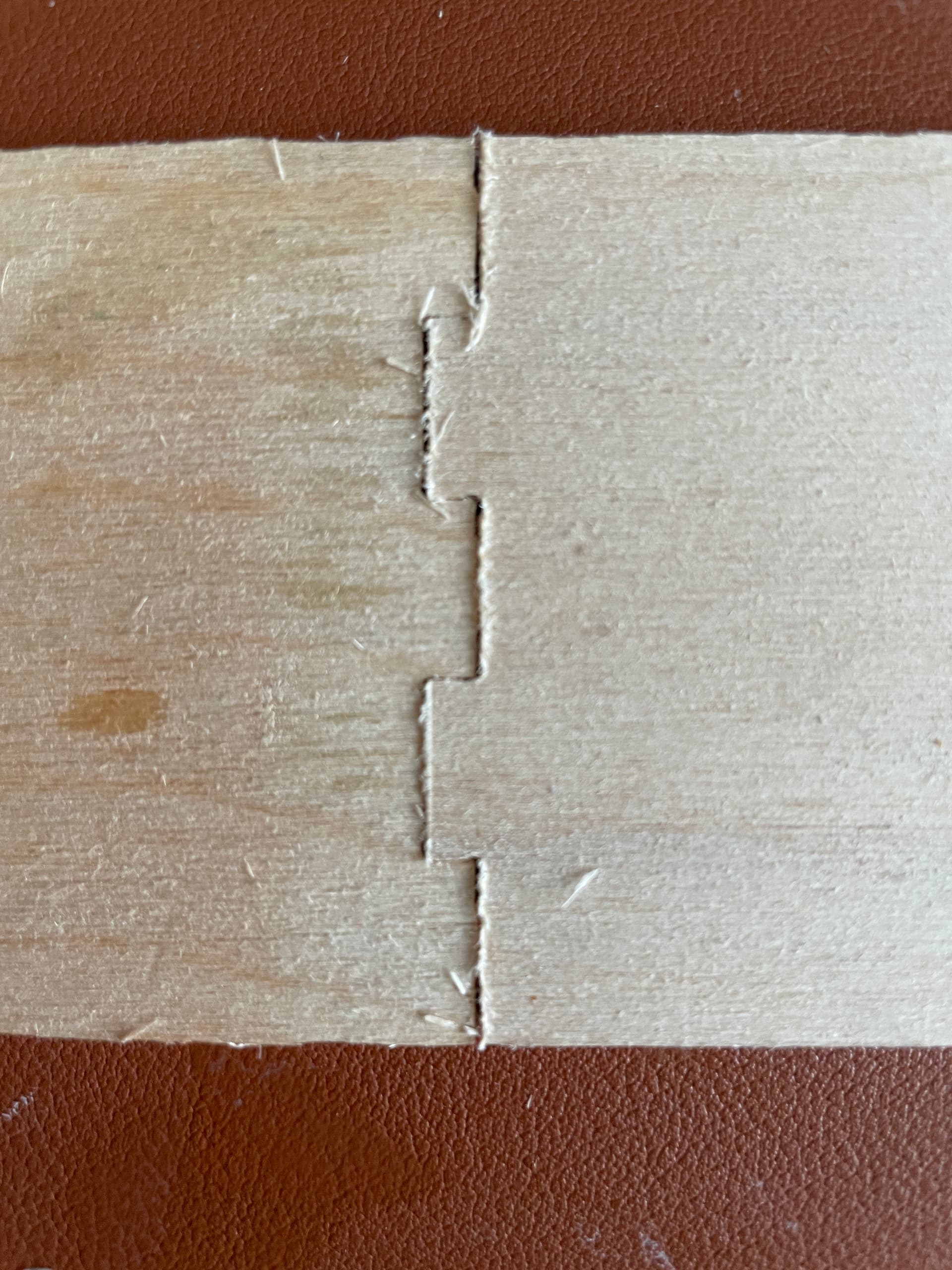
With my tray, though, the tabs and slots are all being cut over/undersized. The edges are not exactly square either. I suspect it’s a tool settings issue. The cuts in the photographs were done with a 3.175 flat end mill. The speeds and feed settings were copied from the retailer where I bought the end mills suggestions. The material is a piece of laminated flooring, made from MDF by the looks of it, and is 9.7 mm in thickness. DOC was 3 mm.

Sorry that this is a little long-winded, but I have tried to include as much info as I think could be useful. If any further details are required, please ask. Thank you.


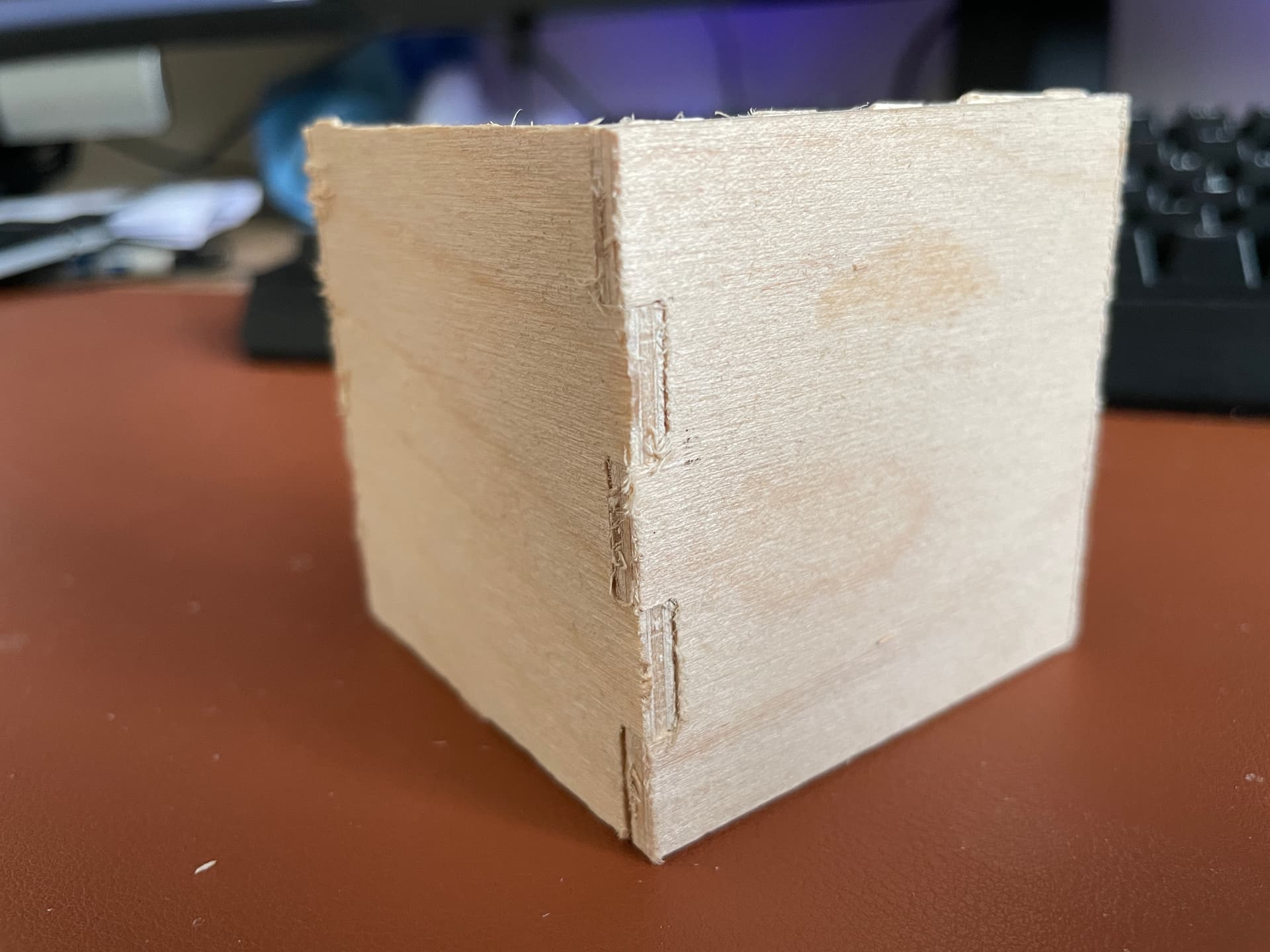
Two corner pieces that should interlock


Two sides that should interlock


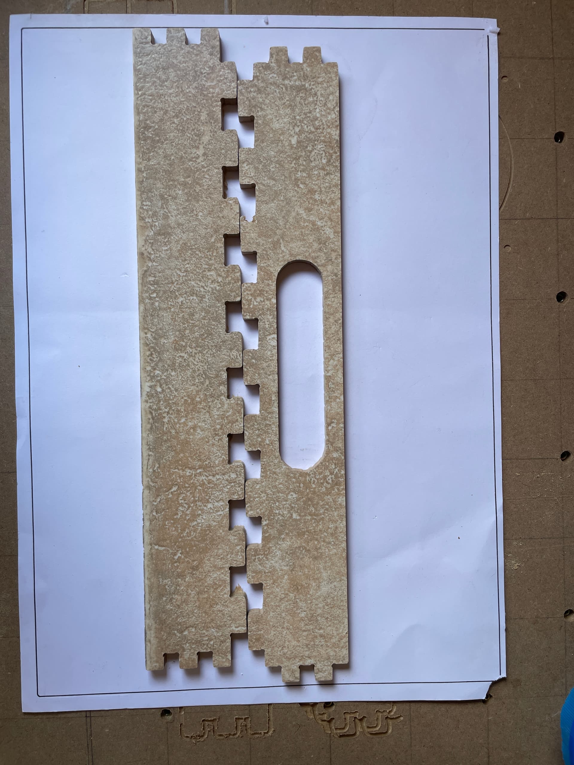
The black square on the paper is the one I created to check the squareness of the CNC (the paper wasn’t quite square on the spoil board)


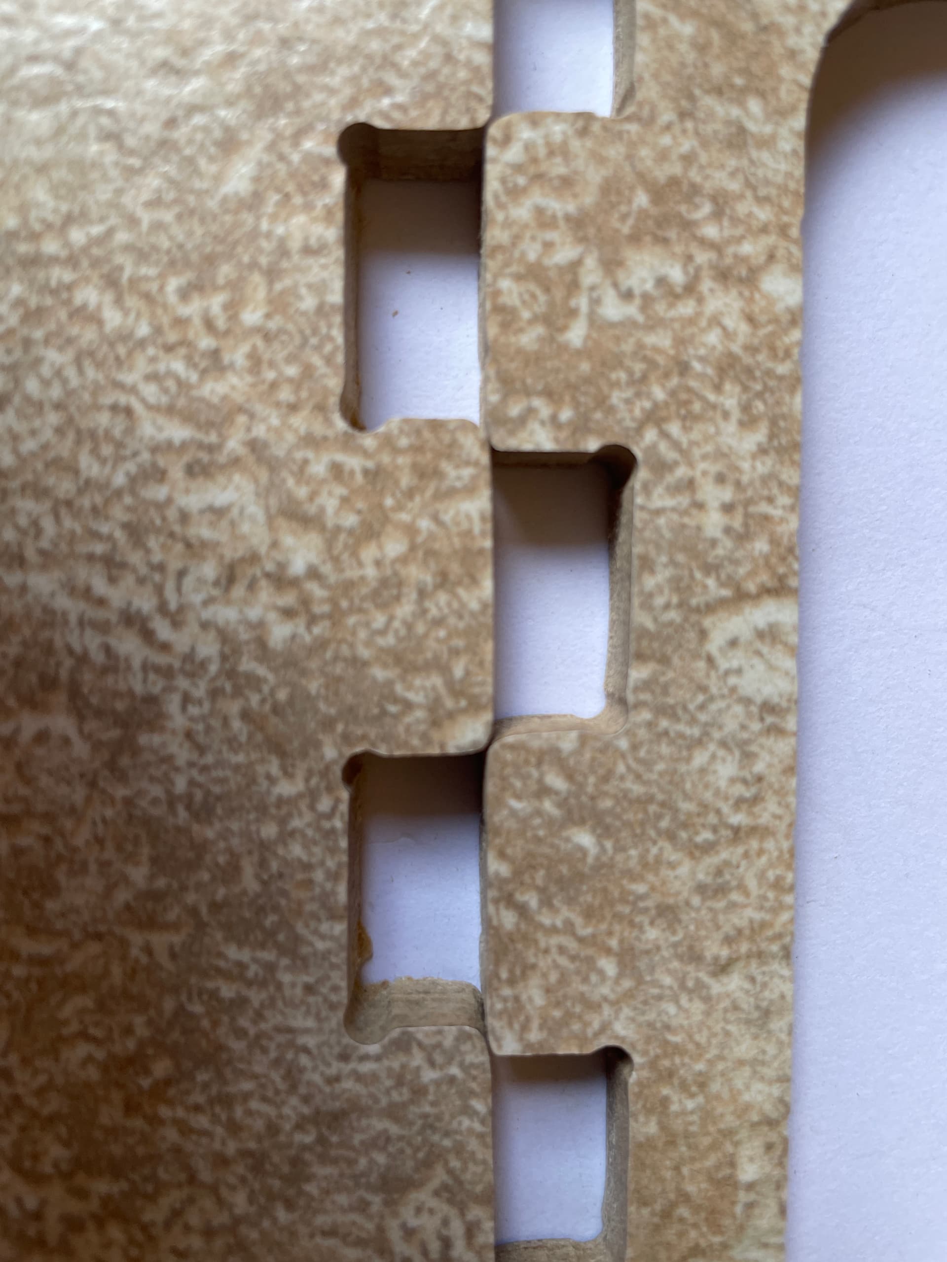
Close up of tabs that should interlock
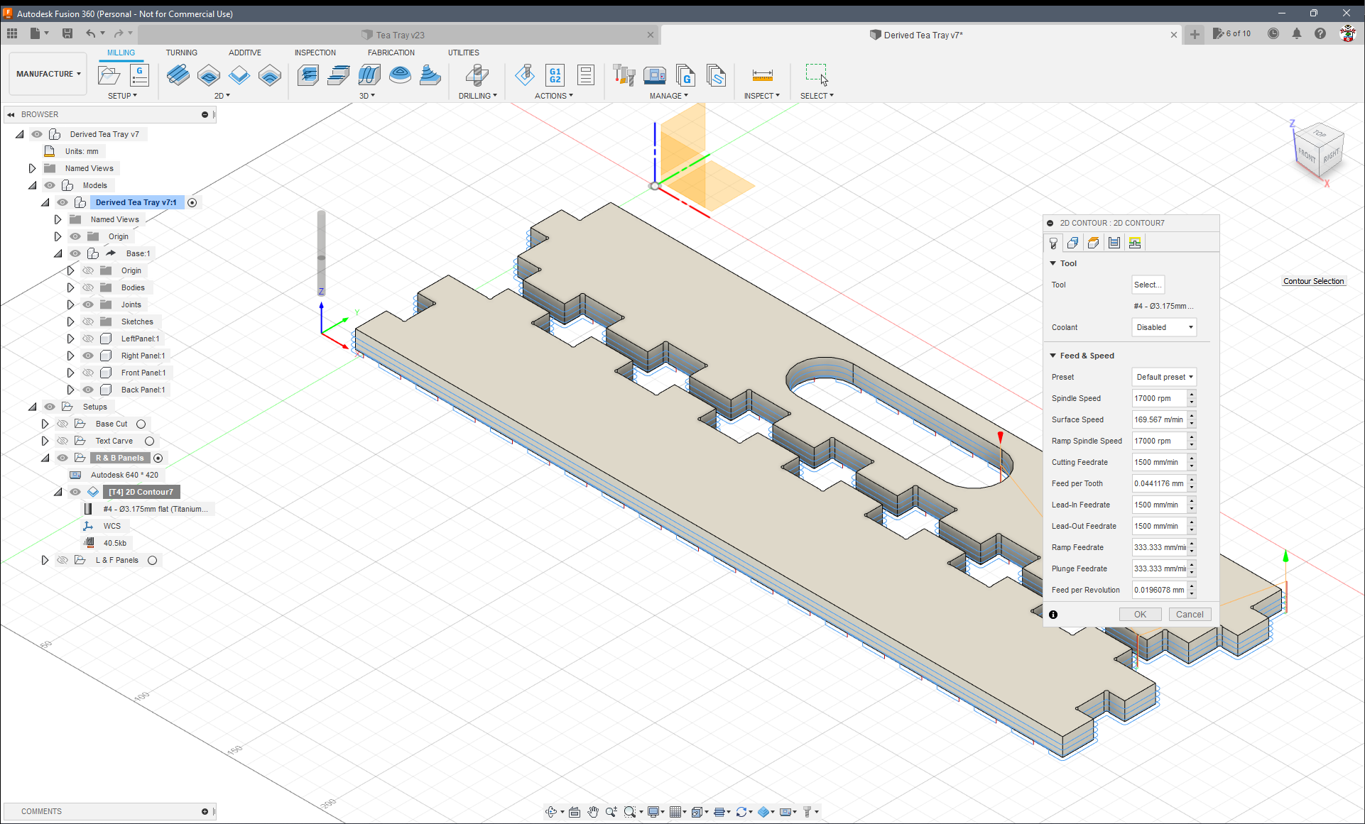

Tool settings


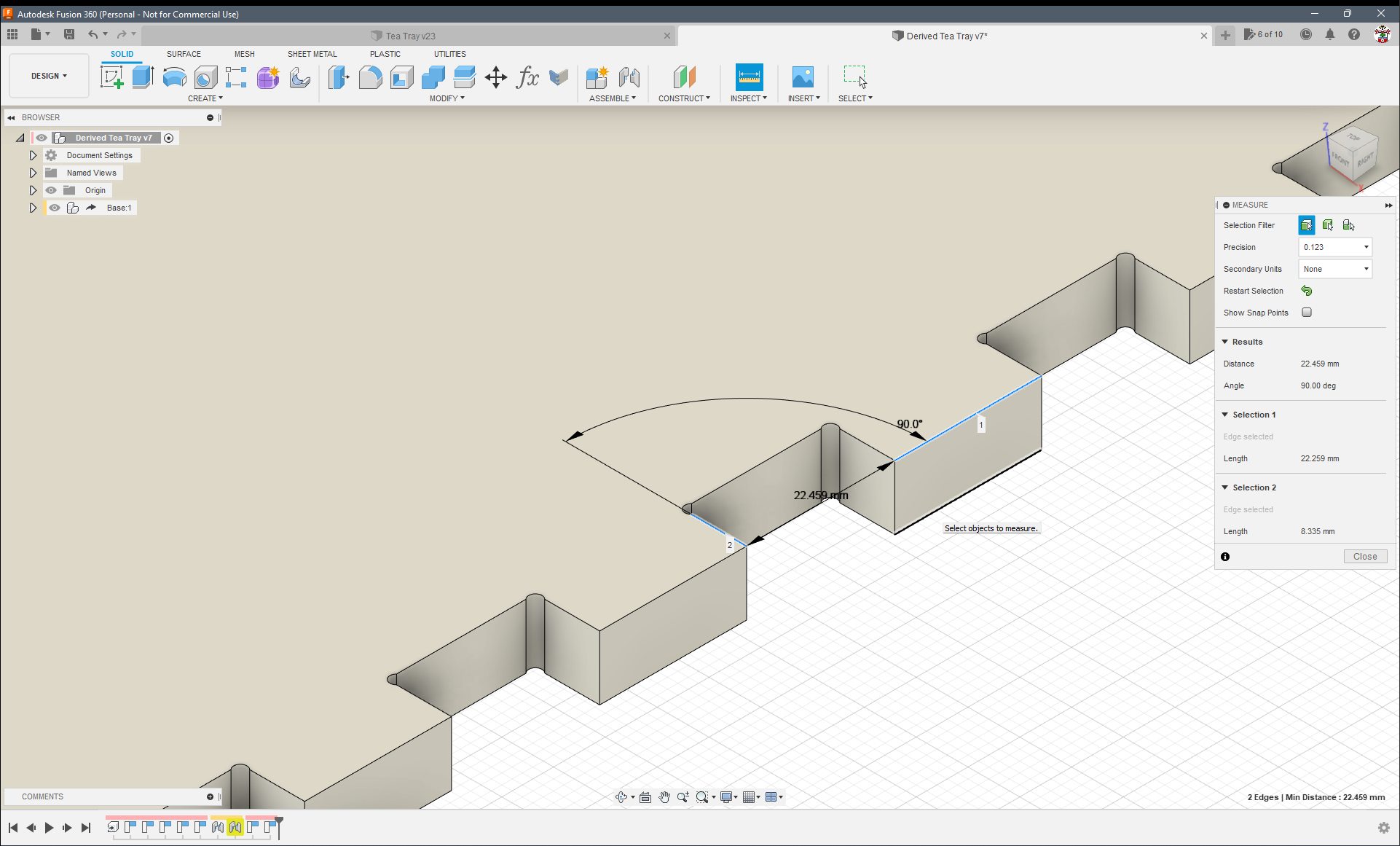
Tab and slot measurements


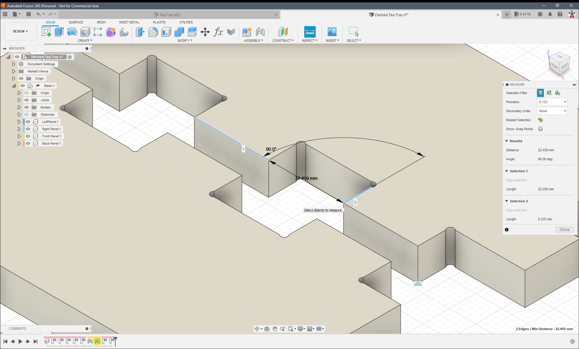
Same as above but different edges


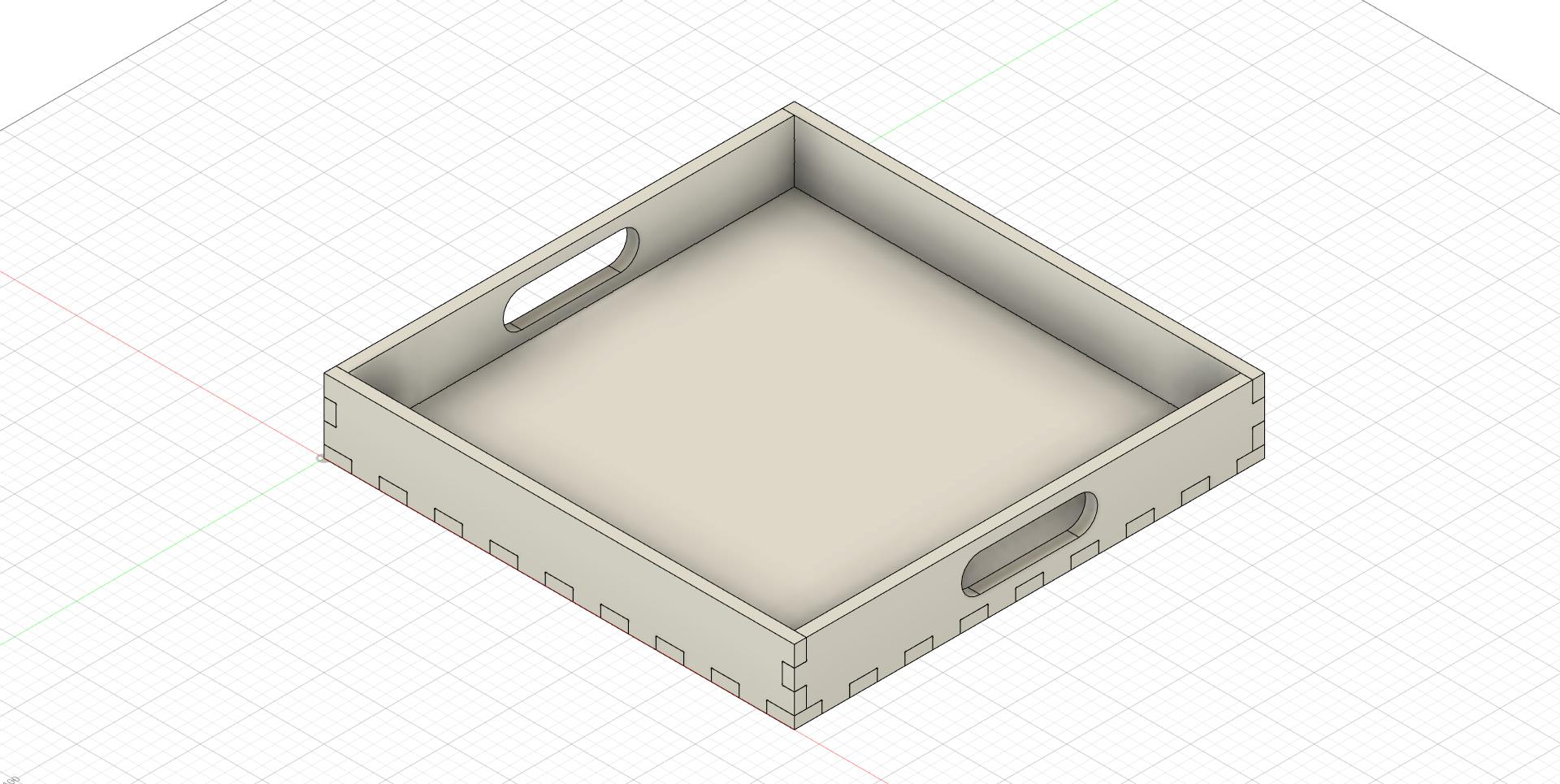
The tray I am trying to create.

Some ideas:

  1. Make sure you have the bit size correct.
  2. Add a finishing pass. Although that error looks too large for just machine flex
  3. Check the grub screws that hold the pulleys to the motor shaft.
  4. Do some jog movements. Move it 100mm one way, measure the difference, and make sure it goes back to the starting place. If it doesn’t, then you have backlash or scale issues. You should not have to change the steps/mm to calibrate anything. It should be very close to perfect with the default settings.
3 Likes

Also check that you’ve selected the correct side of the contour (the little red arrow shows which side the tool is cutting, but it can be misleading when fusion places it in a corner) and that the “stock to leave” setting doesn’t have an innapropriate value.

2 Likes

In my case the problem was that the belts were too loose.
Could also be the core not sitting tightly on the rails.

2 Likes

Thank you all for your replies. I have taken a little time out as the issue was frustrating me as I couldn’t see the problem. So, I managed to wash, polish and clean the inside of my car in lieu of playing with the MPCNC.

I’ll be taking another look at it tomorrow and checking the advice above.

Thanks again

2 Likes

I did a few finger joint projects using Fusion 360 shortly after I finished my Burly. I found it to be a frustrating experience, and I never got to the point where I had a parameterized Fusion 360 setup, nor where I was able to easily repeat the joints. Lately I’ve done a bunch of finger joint projects using my laser (on the Primo)…over 30 to date, and these projects have made me want to revisit routed finger joints.

Looking at your pictures:

  • Given the wonky edges on some of the fingers, I suspect a mechanical issue with your machine. Shortly after upgrading to a Primo, I found my core clamps loose, giving me inconsistent cutting. Later, I had issues creep back in, and I found a broken core clamp (probably overtightened it).

  • Once you have the wonkiness figured out, I suggest you do some test cutting. Model two, small pieces with just two fingers each. Cut out the pieces and measure the result with calipers. If everything is working correctly, and you’ve set up the toolpaths in Fusions 360 correctly, the width of the fingers, and the width of the slots should nearly match, and the width of the finger should be very close to the size you modeled in Fusion 360. If they are not nearly the same size, you will have to do some exploring to figure out the issue.

  • A near match in size will not allow your finger joints to push together. You need some tolerance in the finger joints in order for them to fit together. Some tutorials indicate the tolerance should be modeled into the design. I tried this, and, when I got the tolerance right, the joint worked, but it seemed like a lot of work in Fusion 360. Another thing I tried was using negative stock to leave in the contour tool path to create tolerance. This works, but it also shortened the fingers by the tolerance amount. If that is important, you may have to model the fingers a bit longer than the width of the material to allow for the extra material removed due to a negative stock-to-leave setting.

If you cannot get a near match in finger width wrt the model size and the size of the slots, author the cut of a simple square. Look at the g-code of that square you’d specified in Fusion 360 and make sure the g-code is cutting a square of the proper size. In doing this calculation, you need to take into account the diameter of the router bit.

2 Likes

OK, I think I have solved the issue (at least on a test piece). I modelled a couple of small pieces and used the 2 Fusion 360 add-ins to create the finger joints and dog bones corners.

I then slowed everything down using Ryan’s suggested starting parameters (8 mm/s feed rate, 3 mm/s plunge and 1 mm DOC). Before running the cut, I double-checked the machine to make sure all was well (it was).

I then ran the job and could immediately see improvements as it progressed. Once complete, I cleaned it up a little with a scalpel and was pleased to find that the pieces interlocked almost perfectly.


Once again, thank you to those that offered advice, it was much appreciated. Now to try with a larger workpiece.

8 Likes

It’s great to hear that it did work out for you, though I think that it can’t be the solution, you are now moving at close to half the speed I am going (1200mm/min). Did you check the belts? :smiley:

1 Like

I know the speed is slow, but I’m using it as a starting point and will increase in increments to see if and when the cuts deteriorate. I think my belts are fine too.

1 Like

Okay, cool. :slight_smile: As you can see in my thread, it took me 1.5 years to figure out why my fingerjoints were off (hint: the belts… :sweat_smile:).

1 Like

Success at last.

I now think the problem is with the gcode that Fusion 360 produces. After following the advice given earlier, including tightening my belts again, I decided to try and get the models into EstlCam.

I managed to do this and set up the cuts - and they came out great. The measurements are within a couple of hundredths of a mm, and the fingers interlock. I do need to reduce the tolerances to get a tighter fit, but I can easily do that.

The speed was 15 mm/s with 1 mm DOC. I do plan to go faster :yum:

I just hope it’s repeatable when I try it on the project’s full size pieces.

Thanks once again to those that offered advice.

7 Likes