I’ve been trying for a few days but can’t seem to have any luck. I just tried wiring up the Rambo board I purchased from V1. I’ve never seen the power light come on. I have nothing else plugged into the board, and verified the power supply is generating 12v. Initially I used the adapter for the barrel jack but after that didn’t work I cut the barrel jack off and still it doesn’t seem to be working. Any ideas? I don’t have extra fuses otherwise I would try that but I’ve tested them with a multimeter and they seem to be fine.
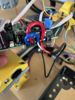
It is not completely clear in the picture, but if red is positive, it appears you have your wiring reversed. This is how it should be wired:
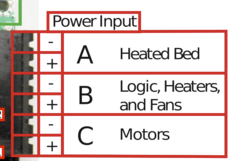
It looks like the blue wires are being connected to the positive posts.
Here’s what I got, White is positive.
I think you need to recheck the output of your power supply. I’ve never seen a red wire on a DC power supply be the negative side. I’ve seen ground be a variety of different colors, but, in my experience, red has always been positive. It doesn’t mean it cannot happen, but it is something to check carefully.
1 Like
I know I hear you. I read somewhere on these forms it said they can be any color? I ordered some fuses just to rule it out. I think after I reversed the polarity, after my first post I blew one.
4 Likes
Wow, that’s a first for me with a red negative. Based on my reading on this forum, it is rare for a Rambo board to be DOA, but it is looking like there is a problem with yours. V1 flashes the firmware, so it was running when it shipped. A couple of other things you can check out.
- On the forum, I’ve seen bad power supplies that read 12V when checked, but drop below usable voltage with any load is applied.
- I’ve seen issues with the screw terminals getting a good connection.
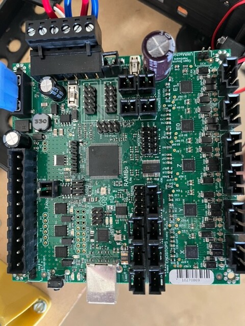
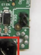
In the corner of your board near the steppers, there are two 12V pins labeled ‘X30’. These two pins are beyond the fuses and on the motor rail. You can check there to see if you are getting power to the motors and not the logic.
3 Likes
Just to be sure, do you have your leads in the right place on the multimeter? 
I know there is reverse polarity protection on the Rambos. I don’t think it should blow a fuse either, just not work.
X30 for checking the power and the fuses is a good next step though.
1 Like
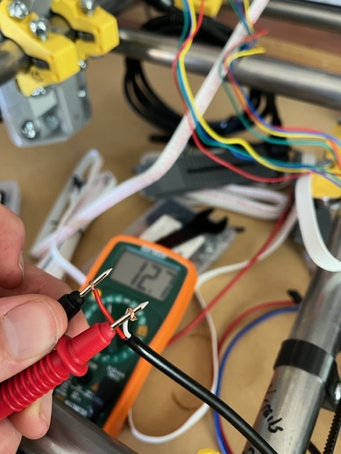
Soooo… it turns out my multimeter was wired backwards. Given that it is now wired correctly, I’ve tested the “x30” pins in both polarity and have 0 volts. At the power bank I still have 12v. If the power supply were bad would it still show 12v where the wires are connected? Im starting to think I blew a fuse somewhere along the way.
I blew a fuse somewhere along the way.
To get the behavior you describe, both fuses would have to be blown.
This is not something I’ve ever done, but if I was troubleshooting this problem, I’d figure a safe ground pin to attach the ground lead of my multimeter to, then, with the power on, I would test the voltage on both sides of each of the two smaller fuses. The large, bladed fuse is for the heated bed, which is not used for the MPCNC.
If you have power on one side of a fuse and not the other, then you have a blown fuse. If you don’t have power on either side of the fuse, then you likely have some sort of wiring issue…screw terminals not seated correctly, insulation on the wire, etc.
2 Likes
F2 looks like its no good, F3 has .05v coming through, I’m assuming that’s not correct. Thanks for the help!
If you take the one you think is bad out, and switch the multimeter to measure resistance, the resistance should be small. A broken fuse will have infinite resistance.
1 Like
Unfortunately, reverse polarity does usually pop those fuses. I used to use a couple 2 pin connectors for flashing and if I missed I had to replace fuses.
3 Likes
So I got it to work with a fuse replacement. But now my display screen has two or three think lines going through it. Any ideas? Thank you in advance.
1 Like
That usually means the actual glass part of the LCD has a bad connection with the zebra cable just under it. Try squeezing the black frame around the glass to the PCB it is immediately attached to see if that fixes it temporarily.
2 Likes
That worked I squeezed and moved it around. It seemed to resolve the problem.
2 Likes
If needed you can usually get some needle nosed pliers under the pcb and bend the tabs a bit tighter