SKR 1.4 Turbo with 2209 Endstops not working

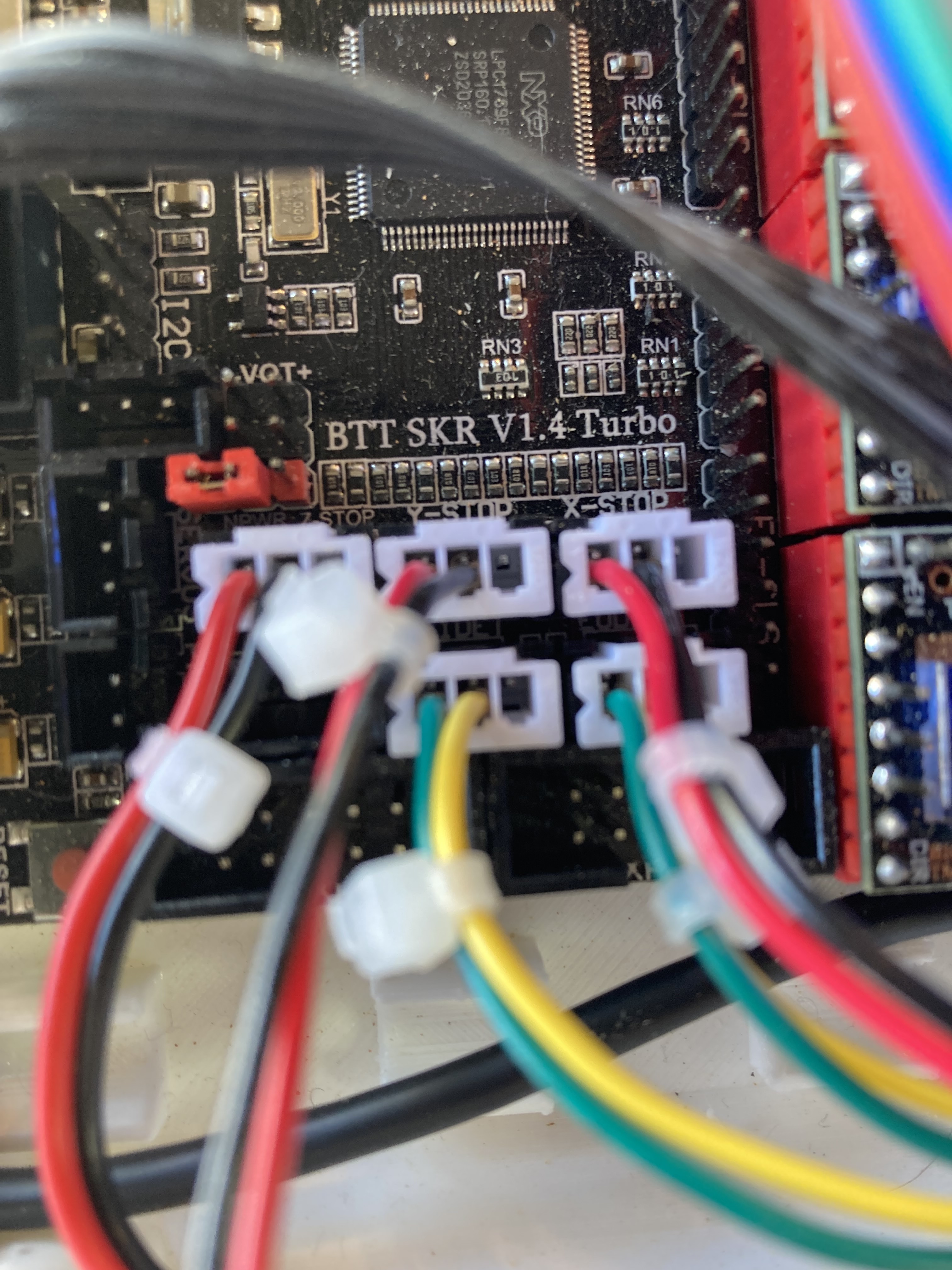
I have a SKR 1.4 Turbo. I am running the firmware [Firmware 2.0.9.2]

My endstops don’t work at all. No matter what I do M119 reports

Send: M119
Recv: Reporting endstop status
Recv: x_min: open
Recv: x2_min: open
Recv: y_min: open
Recv: y2_min: open
Recv: z_min: TRIGGERED
Recv: ok

I have tried putting like suggested in this https://forum.v1e.com/t/mpcnc-duel-end-stops-always-triggered/30571/4

No matter M119 reports no change.

I also ran M43 and nothing would change either

Send: M43 I
    Recv: PIN: P0_00        <unused/unknown>                       Input  = 1
    Recv: PIN: P0_01        <unused/unknown>                       Input  = 1
    Recv: PIN: P0_02_A7     TXD0                                   Input  = 1
    Recv: PIN: P0_03_A6     RXD0                                   Input  = 1
    Recv: PIN: P0_04        <unused/unknown>                       Input  = 1
    Recv: PIN: P0_05        <unused/unknown>                       Input  = 1
    Recv: PIN: P0_06        <unused/unknown>                       Output = 1
    Recv: PIN: P0_07        <unused/unknown>                       Input  = 0
    Recv: PIN: P0_08        <unused/unknown>                       Input  = 1
    Recv: PIN: P0_09        <unused/unknown>                       Input  = 1
    Recv: PIN: P0_10        <unused/unknown>                       Input  = 1
    Recv: PIN: P0_11        E0_DIR_PIN                             Output = 0
    Recv: .                 X2_DIR_PIN                             Output = 0
    Recv: PIN: P0_15        DOGLCD_SCK                             Input  = 0
    Recv: PIN: P0_16        LCD_SDSS                               Output = 1
    Recv: .                 SDSS                                   Output = 1
    Recv: PIN: P0_17        <unused/unknown>                       Input  = 1
    Recv: PIN: P0_18        DOGLCD_MOSI                            Output = 1
    Recv: PIN: P0_19        Y_STEP_PIN                             Output = 1
    Recv: PIN: P0_20        Y_DIR_PIN                              Output = 1
    Recv: PIN: P0_21        Z_ENABLE_PIN                           Output = 1
    Recv: PIN: P0_22        Z_STEP_PIN                             Output = 1
    Recv: PIN: P0_23_A0     TEMP_1_PIN                             Analog in =     0
    Recv: PIN: P0_24_A1     TEMP_0_PIN                             Analog in =  1023
    Recv: PIN: P0_25_A2     TEMP_BED_PIN                           Analog in =  1023
    Recv: PIN: P0_26_A3     <unused/unknown>   Analog in =   842   Input  = 0
    Recv: PIN: P0_27        <unused/unknown>                       Input  = 1
    Recv: PIN: P0_28        BTN_ENC                                Input  = 1
    Recv: PIN: P0_29        <unused/unknown>                       Input  = 1
    Recv: PIN: P0_30        <unused/unknown>                       Input  = 0
    Recv: PIN: P1_00        POWER_LOSS_PIN                         Input  = 1
    Recv: PIN: P1_01        E1_CS_PIN                              Input  = 1
    Recv: .                 Y2_SERIAL_TX_PIN                       Input  = 1
    Recv: .                 Y2_SERIAL_RX_PIN                       Input  = 1
    Recv: .                 E1_SERIAL_TX_PIN                       Input  = 1
    Recv: .                 E1_SERIAL_RX_PIN                       Input  = 1
    Recv: PIN: P1_04        E0_CS_PIN                              Input  = 1
    Recv: .                 X2_SERIAL_TX_PIN                       Input  = 1
    Recv: .                 X2_SERIAL_RX_PIN                       Input  = 1
    Recv: .                 E0_SERIAL_TX_PIN                       Input  = 1
    Recv: .                 E0_SERIAL_RX_PIN                       Input  = 1
    Recv: PIN: P1_08        Z_SERIAL_TX_PIN                        Input  = 1
    Recv: .                 Z_SERIAL_RX_PIN                        Input  = 1
    Recv: PIN: P1_09        Y_SERIAL_TX_PIN                        Input  = 1
    Recv: .                 Y_SERIAL_RX_PIN                        Input  = 1
    Recv: PIN: P1_10        X_SERIAL_TX_PIN                        Input  = 1
    Recv: .                 X_SERIAL_RX_PIN                        Input  = 1
    Recv: PIN: P1_14        E1_DIR_PIN                             Input  = 0
    Recv: .                 Y2_DIR_PIN                             Input  = 0
    Recv: PIN: P1_15        E1_STEP_PIN                            Input  = 1
    Recv: .                 Y2_STEP_PIN                            Input  = 1
    Recv: PIN: P1_16        E1_ENABLE_PIN                          Output = 1
    Recv: .                 Y2_ENABLE_PIN                          Output = 1
    Recv: PIN: P1_17        <unused/unknown>                       Input  = 1
    Recv: PIN: P1_18        LCD_PINS_ENABLE                        Output = 0
    Recv: PIN: P1_19        LCD_PINS_RS                            Output = 0
    Recv: PIN: P1_20        LCD_PINS_D4                            Output = 0
    Recv: PIN: P1_21        LCD_PINS_D5                            Output = 1
    Recv: PIN: P1_22        LCD_PINS_D6                            Input  = 1
    Recv: PIN: P1_23        BTN_ENC_EN                             Input  = 1
    Recv: .                 LCD_PINS_D7                            Input  = 1
    Recv: PIN: P1_24        NEOPIXEL_PIN                           Input  = 0
    Recv: PIN: P1_25        FIL_RUNOUT2_PIN                        Input  = 0
    Recv: .                 Y_MAX_PIN                              Input  = 0
    Recv: .                 Y2_MIN_PIN                             Input  = 0
    Recv: .                 E1_DIAG_PIN                            Input  = 0
    Recv: PIN: P1_26        X_MAX_PIN                              Input  = 0
    Recv: .                 X2_MIN_PIN                             Input  = 0
    Recv: .                 E0_DIAG_PIN                            Input  = 0
    Recv: PIN: P1_27        Z_MIN_PIN                              Input  = 0
    Recv: .                 Z_DIAG_PIN                             Input  = 0
    Recv: .                 Z_STOP_PIN                             Input  = 0
    Recv: PIN: P1_28        Y_MIN_PIN                              Input  = 0
    Recv: .                 Y_DIAG_PIN                             Input  = 0
    Recv: .                 Y_STOP_PIN                             Input  = 0
    Recv: PIN: P1_29        X_MIN_PIN                              Input  = 0
    Recv: .                 X_DIAG_PIN                             Input  = 0
    Recv: .                 X_STOP_PIN                             Input  = 0
    Recv: PIN: P1_30_A4     BEEPER_PIN                             Output = 0
    Recv: PIN: P1_31_A5     SD_DETECT_PIN                          Input  = 1
    Recv: PIN: P2_00        SERVO0_PIN                             Input  = 1
    Recv: PIN: P2_01        X_ENABLE_PIN                           Input  = 1
    Recv: PIN: P2_02        X_STEP_PIN                             Input  = 1
    Recv: PIN: P2_03        FAN_PIN                                Output = 0
    Recv: PIN: P2_04        HEATER_1_PIN                           Input  = 0
    Recv: PIN: P2_05        HEATER_BED_PIN                         Input  = 0
    Recv: PIN: P2_06        X_DIR_PIN                              Input  = 1
    Recv: PIN: P2_07        HEATER_0_PIN                           Input  = 0
    Recv: PIN: P2_08        Y_ENABLE_PIN                           Input  = 1
    Recv: PIN: P2_09        <unused/unknown>                       Input  = 0
    Recv: PIN: P2_10        <unused/unknown>                       Input  = 1
    Recv: PIN: P2_11        Z_DIR_PIN                              Input  = 1
    Recv: PIN: P2_12        E0_ENABLE_PIN                          Input  = 1
    Recv: .                 X2_ENABLE_PIN                          Input  = 1
    Recv: PIN: P2_13        E0_STEP_PIN                            Input  = 1
    Recv: .                 X2_STEP_PIN                            Input  = 1
    Recv: PIN: P3_25        BTN_EN2                                Input  = 1
    Recv: PIN: P3_26        BTN_EN1                                Input  = 1
    Recv: PIN: P4_28        <unused/unknown>                       Input  = 1
    Recv: PIN: P4_29        <unused/unknown>                       Input  = 1

pinoutpng

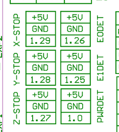
    Recv: PIN: P1_25        FIL_RUNOUT2_PIN
    Recv: PIN: P1_26        X_MAX_PIN
    Recv: PIN: P1_27        Z_MIN_PIN
    Recv: PIN: P1_28        Y_MIN_PIN
    Recv: PIN: P1_29        X_MIN_PIN

This does not appear to match up with the M43 dump, but I would still expect some sort of change.

I am just wanting to know if there is another way to test if I have managed to kill the board or if I have some sort of config issue?

Any help or suggestions is very much welcomed.

The link you provide has a list of firmware. Which one are you running? For end stops, you should be running one of:

  • V1CNC_SkrTurbo_Dual_8825
  • V1CNC_SkrTurbo_Dual_2209

If you are running one of these versions, then remove all the end stop wires and execute the M119. It should show the X and Y end stops as triggered. If it doesn’t show them as triggered, then you either have a firmware problem or a board/pin problem. If it does show them as triggered, then you likely have a wiring problem. Note that V1 set the firmware up to expect normally closed connections/switches. Also, unless you wired the end stops incorrectly as some point (they look right in the picture you provided) so that 5V was wired to ground, it is highly unlikely it is a pin/board issue. I can see one pin bad, but not all of them being bad.

I am running the

  • V1CNC_SkrTurbo_Dual_2209

If I remove all the wires and run the M119 nothing changes. x and y show open and z triggered. I have not managed to get it show anything different.

Send: M119
Recv: Reporting endstop status
Recv: x_min: open
Recv: x2_min: open
Recv: y_min: open
Recv: y2_min: open
Recv: z_min: TRIGGERED
Recv: ok

I feel I was careful not to connect the 5V pin to anything. Do you know of a way to test the input to see if I have managed to damage the board?

I have also played with the M43 command and I can not get the inputs to change there.

I might try getting the PWRDET pin to change state.

I by no means an expert on this stuff. Since the pins do not change when you remove the wires, I suspect a firmware problem. Note that this particular firmware version is listed as “untested” by V1 and is not one of the versions listed in V1’s main release point. From the limited amount of information I can track down from your M43 and online sources on pin assignments, it does appear that at least some of the pins are correctly assigned.

This isn’t a workaround, but you could try the 8825 version. That firmware has been around a bit longer, and I hope more people have tried it.

If you short S and Gnd, that should change it. (in most V1 firmware, that should change it from triggered to open).

So it should show TRIGGERED when nothing is plugged in?

I will try the 8825 version and see if the endstops work.

So far everything else is working on the firmware as far as I can see, just the end stops being odd.

Tried 8825 version same behavior. I am starting to get a bad feeling about my board.

Reading is a powerful thing. Following and understanding what is read is way better

BIGTREETECH-SKR-V1.3/issues/335

I did not cut my pins as instructed SKR Pro - V1 Engineering Documentation.

Using a 3 Wire mechanical Endstop without stallguard you dont need to cut diag pin for endstop function

This is the cause of the my issue. I don’t have 3 Wire switches.

I will follow instructions and cut the pin.

1 Like