@vicious1, it looks like my Lowrider kit should be here tomorrow, so I can get the steppers hooked into the SKR 1.2 they sent me.
Anyway, I got your dual endstop firmware compiled and flashed to the board, at least as far as I can tell. The board booted after dropping firmware.bin onto it, and then when I checked it later, the bin had been renamed to firmware.cur (which I take to mean it was flashed and is current).
I also flashed @jeffeb3’s TFT35 3.0 E3 firmware that he has been working on, and have the CNC icons/firmware set up.
Question, are you running in UART mode for your TMC2209s? What about stallguard? I don’t want to clip the pin if not necessary as I’m out of pin header components to resolder at the moment.
I’m reading up on Marlin 2.0, and it looks like you can now set it to Extruder=0 so pin remapping should not be necessary, so if that is the case, it should just be a matter of connecting the steppers to each of their normally assigned outputs and then creating and crimping all of the wiring and connectors so I don’t have any splices anywhere.
Thank you. One additional question: Have you been able to get both the TFT in Touch Mode and something like Pronterface, Octoprint, etc working simultaneously?
I’m looking in the #define SERIAL_PORT section of Marlin. I have to tell the touch interface to disconnect from the SKR Pro before I can run Octoprint against the board via USB port. My understanding is that -1 should work for the primary serial port connection as this is a virtual port in use by the USB, so I configure that, and then I set 1 for SERIAL_PORT_2. This is the only functional configuration I have been able to get the TFT working on. Any guidance you can provide would be great as I’d like both the screen and a computer connection to work simultaneously.
I believe in that case you would have Octoprint hooked up through the TFT. You would use TX and RX pins on the Raspberry Pi and connect them to a UART on the TFT screen. There is a config.ini setting on the TFT to keep the connection even if in “Marlin Mode”.
Using just what you described. Connecting Serial port to - 1 and serial port 2 to 1.
I would expect some conflicts, like if you were printing from pronterface and you sent a job command with the screen. But it should mostly just work like that.
Ok. I’m getting access denied on the USB serial port with that configuration, unless I go into the settings on the TFT display and choose Disconnect. As soon as I do that, the serial port on the board allows connection.
Does it matter whether the USB cable is plugged in later in the process or is plugged in during boot? I have not been able to get testing via either to work.
I was looking at that and using UART3 or 4 for this connect, but have not yet configured my Pi4 for Octoprint for this unit. I’m actually still waiting on the steppers to arrive.
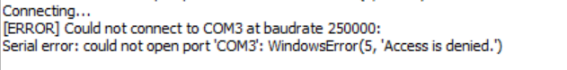
Right now I am using my Windows 10 system and attempting to connect via USB to the SKR Pro 1.2.
I can’t even open the port using Putty, and have tried Pronterface, Arduino IDE Serial Debugging, etc.
No other changes in the firmware configuration yet. I’m building a Pi3 right now (my Pi4 is having issues), and will get that connected and see if I can get some better debugging than:
When I disable the TFT connection, this setting works and I can connect. When TFT is enabled, it doesn’t matter what I set the baud rate to, it will not connect as long as the TFT connection is talking to the board.
I’m not an expert at windows. But if something else has the serial port open (in windows, not skr), then it will give you access denied. I can’t figure out how the screen could affect windows declaring you don’t have permission to open that connection. My memory is that I can connect with both, but I will go give it a quick test.
Sounds good. I’ve run through anything in Windows that may have the port open. My day job is IT Systems Engineer, and sometimes even I get stumped, only to find it is something stupidly simple.
I am using linux. I just started it with the screen attached. I am powering it via USB because it is just on my desk. I then opened pronterface and hit connect. I got one goofy message in pronterface, like “unrecognized character ‘~’” and then sent M503, M115, M119. It all worked fine.
I went to the terminal in the tft and sent M119, that responded fine. The responses went to the right place. They looked normal.
The Config.ini file on the TFT is also set to defaults and I am using the most recent link you posted in the TFT thread. Can you check the config.ini on yours to see if you have the serial_always_on set to 1? Mine is set to 0.
#### Keep Serial Always ON
# Keep UART (Serial communication) alive in Marlin Mode
# Allow seamless OctoPrint UART connection to the TFT's UART/serial expansion port no matter
which mode the TFT is in.
# Options: [0: Disabled, 1: Enabled]
serial_always_on:0
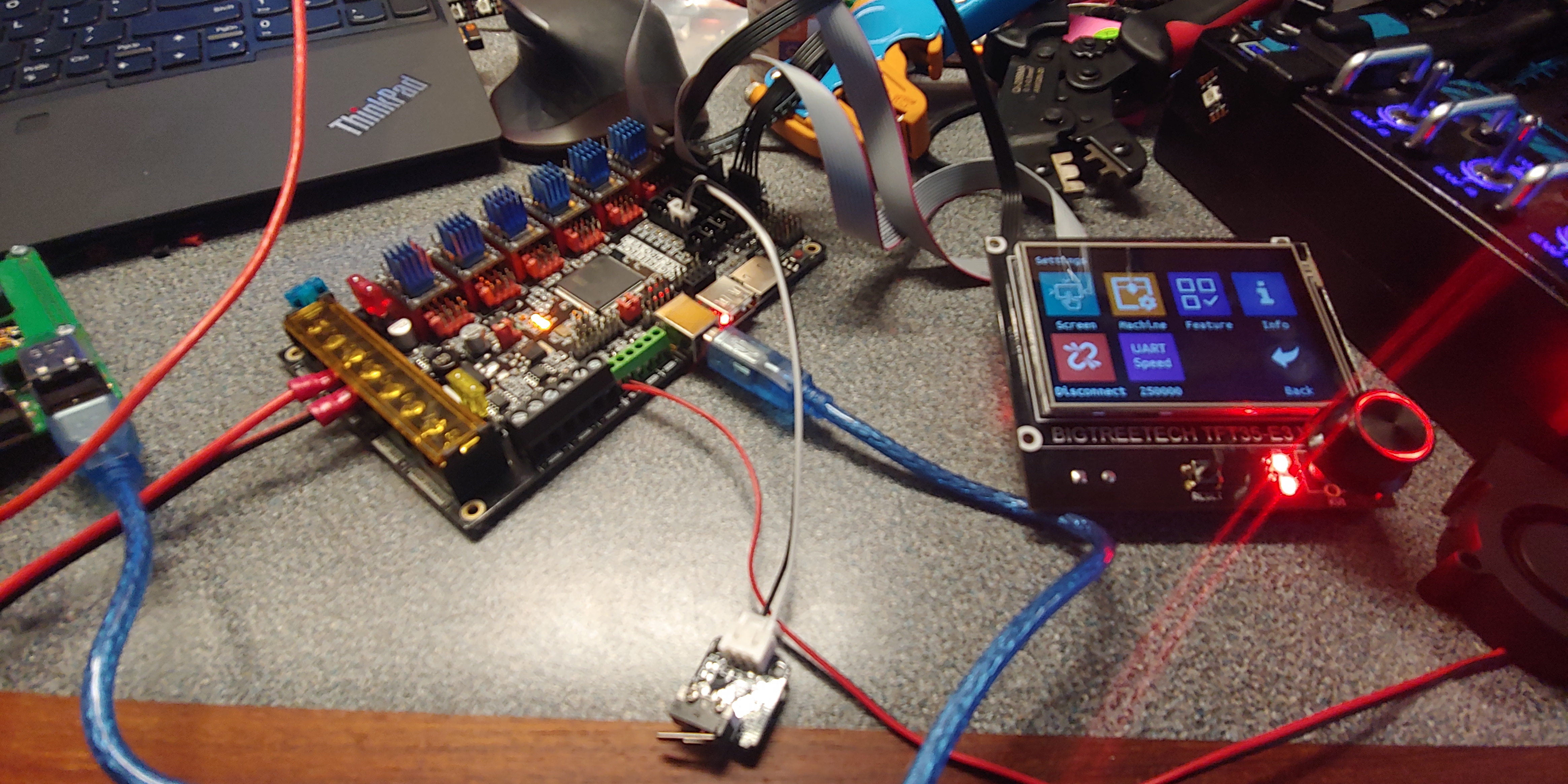
My board is sitting on my desk, powered by an ATX power supply with a breakout board.
Yeah. I’m good now. I’m building endstop jumpers now so I can pin map. One thing that confuses me a bit with this board/firmware:
Z axis is the vertical motion of the gantry with the two steppers connected to the ball screws, correct? The firmware is configured to have Z with only a single endstop and stepper, though Z should have two?
X axis is the motion of the router plate on the gantry, and Y axis is the length of the table.
Why are X and Y axis configured with two endstops and two steppers? X should have a single, Y should have dual. Am I mis-reading the configuration, or is it a naming thing within the firmware that is necessary for MPCNC to function properly?
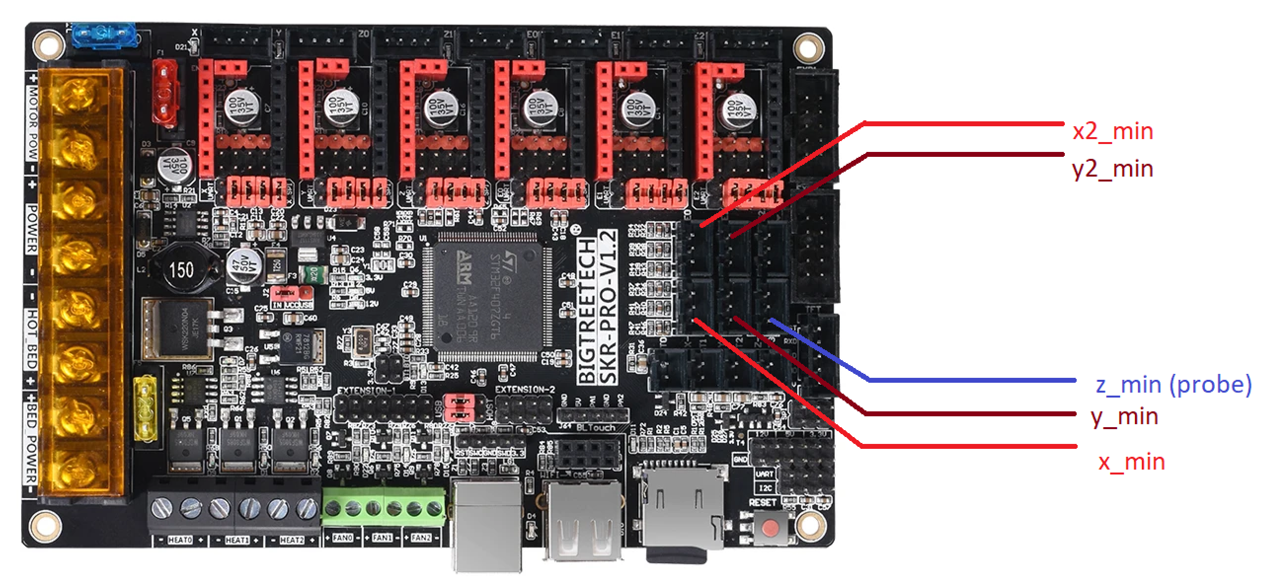
Edit: Pins mapped for X/Y stops and the Z probe. Ground and Sensor are the only two pins that matter, and the 5V pin is not needed. Sorry if this information is redundant for many of you. It’s my first motor controller board like this, and I’m a documentation fiend. Someone somewhere will find it useful.
Sounds like you are building a low rider. The MPCNC has just one Z screw, 2X, and 2Y. This firmware is configured for the MPCNC. I have one configured for the LR I can give you. There is a lot that hasn’t been tested, but it will home down, and use Xmax as the second Z endstop.
Sorry, I should have specified that I am building a Lowrider. The configuration I am seeing makes more sense to me now. I would love to see the firmware you have for it.