Just wondering in a lazy sort of way, has anyone taken the time to tabulate what speeds/depths/performance they get with different materials?
ie is there a ‘mother lode/holy grail’ sort of table with eg 1/8th spiral cutter, Dewalt number 4 set on thumb wheel, X axis speed of 5mm/sec etc with a Z of 5mm etc etc?
While there are no hard set rules because each machine is different, I’m sure that there are at least some guidelines that would work pretty well for most newcomers to educate them as to why certain speeds with certain bits for certain cuts would be ideal?
I was going to do one in Fusion 360 using different libraries, but I’ve found that most of my cuts are the same feed rate with just little differences. I’ve gotten to where I just adjust the feed in the project itself if I can go faster than the rate set on the tool.
The wiki has a Milling Basics page that has some conservative speeds to get most people started.
I am sure that every build is different, no doubt, you would only be accurate on average to within a certain percent, but there are two or three routers being used, the drill bits are not that varied, and the machine design is constant. I wouldn’t want to be liable for a spec, or have to do hand holding tech support for it, but ball park ideas wouldn’t hurt, milling basics is a start, sure. One of the laser cutting softwares’ out there (t2 laser?) let you dial in the material using a drop down, so same kind of idea, but less autistic.
If not actual cutting speeds etc, what to look for to know when it is going right. What to watch for when it isn’t. Some things are obvious, fire starting, bits flying, path wandering, goop sticking to the bit. The parts you get from experience, as starting points, would be helpful. Oh, it’s plastic, let’s not go fast, but go slower, it’s metal, don’t go too slow, but not too fast. That kind of thing is spread out through the forum, could be gathered in one spot for people to argue over.
That’s the rub. If we put up a chart we will get held to it. We’ll have people like Tom salamander posting another video showing how using our speeds and feeds his machine gave him early onset hair loss or some bullshit like that. You have folks that make the machine with 8 inch tall legs and now the endmill is wiggling all over the place. Generally Ryan posts speeds and feeds on his videos, same with mine. Sometimes I don’t but those are experiments and I’ve dialed up the speed in repetier host, so I don’t really know what they are. I also have a bad habit of changing settings in estlcam instead of making a new tool with new feeds. I think maybe the closest we could get would be another gallery of YouTube videos. As long as the speeds and feeds are posted with the video. That way we can point to the video saying “see, those worked, on that machine”.
I totally underestimated the Thomas S effect (can I call it that? Whose name is this really?) until recently. Really, kind of a sad thing. Great point about it being in videos, and THAT being the source. Can’t get the data without simultaneously getting the proof.
That all makes sense. What was sort of lurking in the back of my mind was an equation to give a general rule of LR2 use for turkeys like me… ie some sort of function that you could multiply speed x cut x depth x diam of bit to give a value that when you think about it should be the ‘max Q’ as SpaceX calls it at maximum aerodynamic pressure on the rocket if you are following me, that the machine will work to. So if you have a wider cutter moving more material then it will maybe be a square function or simply linear in it’s effect on the final number or something…
Each machine would theoretically have a ‘cutting/speed/rate/depth coefficient number’ that you could work to?
Dunno. Just sitting here waiting for the first coffee of the day to take effect.
If this was to work then you could have a pretty general cross check on the rest of the parameters of your build maybe?
There are some functions that can be used. One if them is called ‘chip loading’ and there is an equation for it. Fusion 360 calculates it for you. You also have to take into account the RPM of the spindle being used. Unfortunately, the chip loading value for most router bits is higher than the structural rigidity of our machines. So we end up under-utilizing the bits by running them slower.
What works for me is not even thinking in speeds, but rather chip(size) per tooth(cpt) and rpm. I set the rpm as best I can relative to the cutter type and material to prevent burning. Bigger step over means lower feed rate for a given cpt(Google “chip thinning”), so that’s nice. Feed falls out of “how fast are you spinning (speed), how big a chip do you need, and how much is that chip thinning?
I was running some adaptive paths at 100ipm, and getting pretty good results, but it’s easier to miss steps at that speed, and not even the fastest way to get through a cut.
Depth of cut is where it’s at, though. Cut deeper with a little less step over and you can get the same (or better) material removal rate (MRR) and an even (marginally) faster run time for the same MRR because you will have fewer travel moves. Bonus, you remove material with more of the cutting edge, versus only the bottom 1/8”. I use the MRR to compare step over vs doc, but the lack of travel moves means it’s tough to compare pocketing with Adaptive strategies, so I try to start with a reason for one or the other.
I think DOC is the parameter most closely tied to machine rigidity, which is why it’s so tough to put together a decent chart.
Sure, we could say “these settings will probably work”, but then, you’ve already got the milling basics page. Finding what’s optimal has to be an exercise in exploring the machine. My guess is that the cutter manufacturers are fortunate in that the cutter is the week spot, and their commercial customers have way more machine than most cutters can handle, hence the very specific guidelines. I’ve crashed more than one endmill with zero damage because the mpcnc just isn’t strong enough to make a mess out of the tool.
It would be fun to make a test pattern generator that starts with a slow cut and goes faster and faster until you hit the E-stop or the bit breaks or it skips steps or starts a fire. Then you can dial it back by 50%.
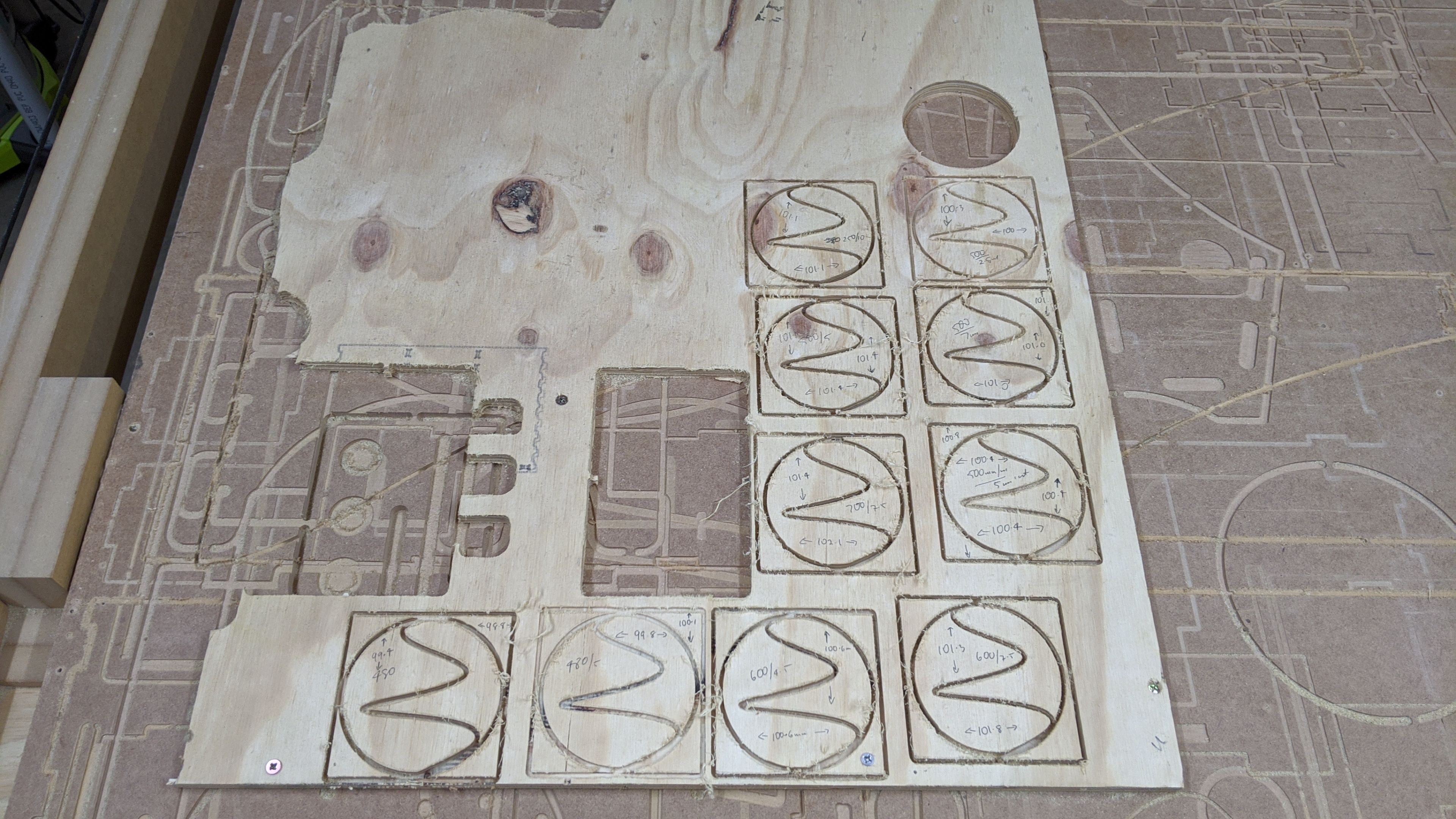
Was off sick from work today, and that never happens but still found the energy to run a series of tests on the LR 2 and have generated a spreadsheet here.
I did a square 100mm square with a circle and a squiggle in it and then cut it out.
Slower is clearly better but the faster you got the error was still only about 1.5%. So on a biggish item it makes no difference.
But the harder I pushed the machine, the bigger the item being cut out became but still within 2%…
Cool. It gets more complicated when you add a finishing pass. You can chew through large material while staying a fraction of a mm away from the line and then come back and just remove that last chunk. You can get very accurate results this way and still go fast. So even though a second pass costs time, it will be faster overall.
I would guess the error is in the absolute, so cutting 1000mm won’t be 1.5% off, but the same total error as the 100mm.
If you are climb milling around the outside of the part, the force on the tool will tend to deflect it outward, leaving an oversize part. Conventional milling around the outside, the force will deflect inward, leaving an undersize part. And these forces and deflections are larger if you go faster or deeper.
For holes it’s the opposite: climb milling leaves an undersize hole and conventional milling leaves an oversize hole.
All machines are wobbly to a degree, it’s just a question if how much. More practical is to see if it can do what you need.
With a finishing allowance you can cut at higher speeds or greater depth without worrying that you will bite into your part, and then a finishing pass that skims off the last little bit can get higher accuracy because the loads are low. This allows machines with some significant deflection to still produce accurate parts without having to go slow the whole time, which can have its own issues.