I have built my own CNC router with 4X Stepperonline NEMA 23 (297 in-oz) motors and DM542T drivers, X, Y/A axis with 1605 ball screws, and Z axis with 1204 ball screw. I am using Arduino with CNC shield, GRBL 1.1 and Universal Gcode Sender.
All is working well, except for what acts like lost steps during acceleration. The problems seem to be related to jogging since the router makes engravings and parts quite well.
When I request 100 mm in X, I get something less, say 97 mm, depending on the value of acceleration. If I tap the X+ button 3X times quickly, the machine reaches full speed, decelerates and stops at 297 mm. If I tap the X+ button three times, waiting for the gantry to stop each time, the machine ends up at 294 mm. It loses 3 mm each time. All axis can be moved easily by hand, by rotating the ball screw.
It seems like an acceleration of 1 (mm/s/s) solves the problem but the system is so slow that this is not a solution. But I have no solution therefore. I am working with Stepperonline and they are talking to me but communication can be difficult and the exchange is slow and so far not very productive.
I am at a loss as to what to do next. I have removed the Z axis motor from the router and driven it “no load” with the same results. Request 4 mm (one full rotation) and I get a few degrees less than 360. Also, if I request 0.2 mm, the motor clicks but does not move.
I’ve had good luck tuning acceleration first then tuning velocity.
Pick a velocity slow enough to be 100% reliable, then slowly increase acceleration until you just start to loose steps during acceleration. Drop the acceleration setting by 5-10% for a safety margin.
Now you can do the same for velocity knowing that acceleration is not too high.
Each axis will need to be tuned independently. Make sure you’re using long enough moves that the axis reaches full speed.
I feel like I have done this, though maybe in a hit and miss sort of way. I will try to be more regimented.
But my gut feel is there is something more fundamentally wrong going on. When I request, what is equivalent to 9 degrees of motor rotation, it doesn’t move at all, just “clicks”. At 1600 steps/revolution, that is 40 steps. This is a motor with no load. It’s a 3 amp motor with 11 amps available.
But I will try your suggestion more carefully and see what result I get.
Anything above an acceleration of 1 mm/s/s gives a response less than the requested value. I can’t go lower than 1. It acts like missing steps but how can you miss steps in a motor with no load and an acceleration setting of 2 mm/s/s? Doesn’t make sense to me.
I designed belt driven stepper systems professionally and never saw a problem like this. We used encoders and much more sophisticated control hardware/software, however. Perhaps that is where this problems lies.
The steppers are trying to move the machine, by turning the ball screws. If the resistance is too high, they will pop backwards instead of moving forward. That is all skipped steps are. The drivers and the controller doesn’t know it has skipped steps.
The force resisting motion is partially because of the acceleration limit. It is also partially from the friction in the system and the ball screws. It will eventually also be from the bit pushing through the workpiece.
If the force resisting is more than the force needed to skip a step, then it will jump backward.
You can:
Decrease the acceleration (which you’re doing)
Decrease the friction (is anything binding? Are your screws properly lubricated?)
Increase the max current to the motors. This will increase the limit before it skips.
Redesign the ratios from stepper motor to axis movement to make it go slower, but with more torque*
If you can’t do any of those things, then you are stuck with a slow machine.
If you change this ratio, be aware that steppers actually drop in max torque as they go faster. So there is a sweet spot. If you change that ratio too much, you can make the motors spin so fast (rpm) at reasonable speeds (mm/min) that you will lose torque and still skip steps, but at high speeds.
My understanding is that ball screws have much higher friction. That, and the cost is a good reason they aren’t in smaller machines. I’m a software engineer though, so take that with a grain of salt.
Thanks for your input. As a mechanical engineer, I’m familiar with your comments/observations. While ball screws have some friction, they have a huge mechanical advantage, so you can drive a heavy load with less torque. I can easily turn each axis with my fingers and since the motors have 17 in-lbs of torque, I figure they should be able to handle what my fingers can do easily. I am supplying 36 volts at the max motor current (4.62 A peak, 3 A RMS) so there is nowhere to go there.
But disconnected from the system, with just the motor and a simple pointer, I get the same results. Jog one revolution, get 355 degrees of rotation, the higher the acceleration, the bigger the error. The error is the same no matter how many revolutions requested, just like lost steps would cause. But with no load, there shouldn’t be any lost steps. Noise? (shielded cable), Arduino issues ??? It is a clone but it seems to be working properly.
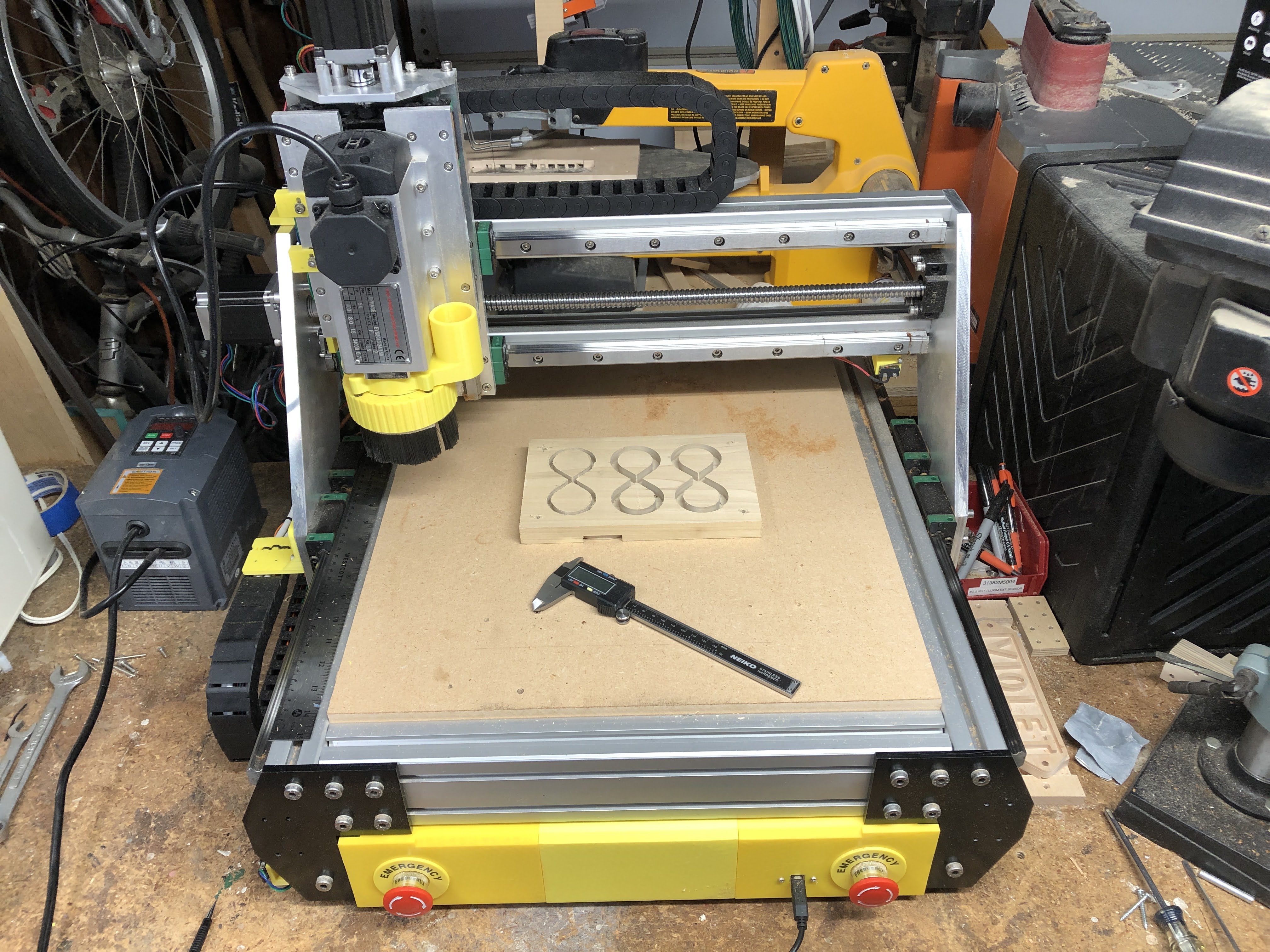
As a CNC router, however, the machine runs great. It just seems to be the jogging that is giving problems. This simple test sign engraving shows that x, y and z operate properly in actual use. This was done at moderate to high speed in about 10 minutes.
With that kind of amperage and voltage and nema 23s, there should be no skipping steps. I don’t have experience with those drivers.
I am still guessing though.
What are the steps/mm? It doesn’t quite fit, but we used to have a Z with 4500 steps/mm and we had to slow it way down because the arduino couldn’t actually toggle the pin that fast and still do all the rest of the computation. That seems like it wouldn’t fit this issue because it would limit your top speed, not your top acceleration.
As I mentioned a little, if the rpms of the motor are very high, the motor creates a reverse voltage that fights the power supply. This ends up making the current going to the motor drop, if the driver gets into saturation. 36V is a lot of voltage to me, so it seems hard to saturate it. But these are nema 23s, which may have much more reverse voltage. If this is the problem, you need to reduce the mechanical advantage, or increase the source voltage. This fits a little better because even though it only has an effect at high speed, it will reduce the torque. The reduced torque, with higher accelerations could cause skipped steps (as in, it can handle 5mm/s/s from a stop. But when it reaches high speed, it can’t.
What if your drivers are being disengaged between jogging. And there is a delay between enabling them and the driver being ready to move? The uno doesn’t know this. It turns on the enable, starts sending pulses, and the driver ignores them for 500ms and it loses 3mm. If you drop the acceleration, the number of steps in the 500ms is smaller.
When you engrave, it leaves the drivers enabled, so there is no delay and everything is fine.
There is a setting in $$ for how long to leave them enabled after a move, and setting it to 255 or something will make them on permanently. Try that and then make the jogs again.
The thing that doesn’t make it seem like skipping steps is that skipping steps is loud. So if the only symptom is a bad measurement, then that doesn’t sound like skipped steps.
Steps/mm are 320 for x and y/a, 400 for Z. 1600 pulses/revolution (8X microstepping) and 5 mm/rev for X/Y and 4 mm/rev for Z. (1605 and 1204 ball screw respectively). I have tried 2X microstepping and 16X with no real difference in the performance during jogging. As for voltage, the driver can take 48 volts but 36 was a compromise, otherwise I would have to have two supplies. Hard to believe back EMF is a problem but people do discuss it. I have never had to deal with that issue in my past.
I don’t feel missed steps is my issue. Curiously, I don’t have any hold current either. There is a DIP switch that sets hold current at either 50% or 100% of current. I complained to the manufacturer that I don’t measure any voltage in the idle condition on either phase of any of the motors (there are 4 total, with 4 drivers). The manufacture performed a test and measure either 1.8 volts or 3.5 volts across one phase (nothing across the other) depending on the switch setting. I measure 0.0 either way and can easily rotate the ball screw by hand with power applied to the system. This may be a clue to what is happening as well but is it a faulty set of drivers I have or a setting?
Thanks for the thoughtful analysis! I will experiment with the enabling issue, looking for the $$ code.
I’m at my computer, so I can see that it would be $1=255. In this case, it would be grbl disabling the motors when idle, not the drivers disabling themselves.
I sure hope that is it.
I maybe spend too much time around here, or maybe I just don’t understand the scale, but that machine looks too small to have so much power in the motors . Especially for wood. But, like I said, around here, nema17 and belts are the norm.
I will try it. Reprap.org shows a command, M17, that turns on all stepper motors. Since I don’t seem to have any holding current, I thought I might try this as well. Not sure of the syntax however.
As for the machine, I want the capability of machining aluminum as well, hence the beefiness. Most of my medical designs were NEMA 17s w/ belts but they didn’t have to do any work, just move fast.
I am in no way trying to make you regret or second guess your choices. It looks nice and beefy.
Just to give you an example of what I am used to though, the machines around here are all nema 17 with belts and controller boards used on 3D printers with integrated drivers. And we definitely have a lot of success. Even with aluminum and a few with thin sheets of steel. gallery-mpcnc
A few other GRBL settings to consider that set jog speeds:
$110 - X max rate, mm/min
$111 - Y max rate, mm/min
$112 - Z max rate, mm/min
$113 - A max rate, mm/min
$114 - B max rate, mm/min
$115 - C max rate, mm/min
Yes. These are the only places I know of to set these values so I have been changing the rates here using UGS.
Since I see a problem jogging if the acceleration is > 1 mm/s/s, with no load, I don’t think acceleration is the problem. You can’t go slower than 1 mm/s/s.
Setting the $1 to 255 seems to have solved two problems!
I now have holding current. I can measure a couple of volts on one of the phases even when the system is idle. Not really necessary with a ball screw system, but It bothered me that it wasn’t there before.
The jogging problem is improved or fixed, not sure quite yet but I will check that out today.
Great detective work! Surprised the vendor didn’t suggest this.
PS - Since you are on a roll, after I leave my system on and connected to my laptop for long idle periods, I often find that the Universal Gcode Sender is no longer responding to the Uno. The Uno is still connected to the com port and UGS recognizes this but all the buttons are greyed out or give an error. I must totally shut down the laptop, not just restart but shut down! I’ve tried disconnecting UGS from the Uno during idle periods, then reconnecting when I want to use the system but that does not seem to help. Any ideas?
You’re very good at coming up with confusing problems
My first thought is that maybe the uno is in some kind of alarm state. Is there a serial log you can see or a place to force a few commands over to the uno? Even sending ? On a console might help give useful data.
The difference between restart and shutdown is interesting. During shutdown, the hardware gets turned off and back on, but not during a restart. So that makes it sound like some component of your laptop (like a usb hub ir something) is not working right until it gets reset.
Maybe one of the more versed grbl users will know something but I haven’t seen that before.
You could try using cncjs on the v1pi image on a raspberry pi and skio the UGS all together and that would probably skip this peripheral that is acting up.
I haven’t seen that behavior myself, but I only used UGS for a little while for initial troubleshooting and don’t recall leaving it connected for a long time. I switched to cncjs on the v1pi image. I haven’t used my machine in several days, but the pi is running and the USB is connected, so I just tried pulling it up and it responded immediately with status - no greyed out icons.
I realize this doesn’t shed any light on the issue you’re experiencing.
It may not be relevant, but most laptops will turn power off to the USB ports when in sleep mode and there are a lot of different sleep mode levels. Perhaps the port is getting shut down and not getting turned back on. A restart doesn’t do a hardware initialization, but of course a power cycle does.

 . Especially for wood. But, like I said, around here, nema17 and belts are the norm.
