I’ve been building my mpcnc and finally got to a point that I could test the first stepper motor. It went “okay”. When I moved the axis, sometimes both would move, most of the time 1 would move, sometimes neither would move. I’m running the steppers in series. I believe It’s related to stepper output voltage but would like someone smart than me to confirm!
My setup:
Creality 3d mainboard with a4998 drivers. Stock voltage
Stepper Motor: Bipolar 1.7A 40Ncm(56.2oz.in) (https://www.amazon.com/dp/B075JG2MVS/ref=cm_sw_r_cp_api_i_44X7Eb1HANS8C)
I haven’t checked the voltage, but plan to do that next. I have a new born so my time is very limited now.
From the product page it looks like these want 12v? From another video about adjusting these drivers, it looks like they’re stock output is <1 volt. What should these be reading?
The input to the board is 12V, typically. The output is constant current, not constant voltage, so the voltage you’ll get at the motor connections is wildly variable, but somewhere between 0-12V.
Unless the drivers are overheating, they don’t usually turn on and off. My first instinct is to tell you to check the wiring. How are the motors connected? Are they in the machine already?
That stepper’s product page says 12V but that’ll be the maximum drive voltage. The actual drive voltage will be much lower, more like 3-4V when stable.
I think you might be confusing yourself with the current limit adjustment of the drivers. These stepper drivers have a reference voltage input that sets the maximum current for each phase. For the drivers that I use, a reference voltage of 1V results in an output current of 2A. That’s nothing to do with the output voltage, that’s simply whatever the input power supply voltage to the stepper driver is. I don’t know what the setup is for the Creality board, but I would suspect something similar.
Do you have a photo or diagram of how they’re wired currently?
I’d recommend starting by adjusting the current limit down lower, or at least poking your finger onto the heatsinks and seeing if they’re getting hot. They could be overheating and then turning off for short periods, potentially.
Then I’d start by just trying to get one to move smoothly. Easy if they’re off the unit, but if it’s fully assembled then perhaps by just taking off the belt. What you’re looking for is the ability to command a move of 50mm or so and have the stepper go through 1.5 turns. If it just twitches or moves a little bit, then you’ve got something wired incorrectly or one of the phases isn’t connected properly.
Once you’ve got that working, I’d rewire it so that both steppers are turning. Make sure that both are turning the same amount and in the directions expected. Obviously, one should be clockwise, one should be counter-clockwise for the same commanded movement direction when viewed from the pulley side.
At that point, I’d put the belts back on and proceed
That’s my general approach to troubleshooting, more or less. Go back to the simplest possible setup and test/diagnose that, then add complexity from there.
Thanks for the reply, kids have literally taken up all my time since my post. I just pulled it out and dusted it off again. Still running into the same problems. Here are some more troubleshooting steps I’ve done.
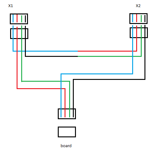
First here is the wiring:
Second…I removed this from the equation. I hooked up the z access directly. I measured the vref on the steppers and found they are different from each (i might have changed these back when?). 1 is around 0.591. Another is 0.860. If I hook it up to the .591 access and move down, it’s smooth. If I go up, it jitters, and sometimes misses. Occasionally it works. If I hook it up to the 0.860, it is successful most of the time, but I still the occasional skip (sometimes it misses some of the travel, sometimes it just jitters and doesn’t move at all. I’m using a power brick power supply hooked up the board and that provides 12v at 4.2a. It’s the only axis hooked up so I don’t think it’s under powered. The higher vref makes it more successful, but the reading I did indicated that .86 is already pretty high, I’m hesitant to go up much more.
Any help is appreciated!
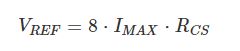
No practical knowledge here, but I picked up a Ramps board recently with the A4998 drivers, and have been doing some reading. You need to determine the R-sense value from the resistors on your board. Common values for the A4998 are 0.05, 0.068, and 0.1. For many of the stepper drivers for the MPCNC, the current value is set in the firmware, and they seem to set to around 0.8A. I see some of the people on the forum running a bit “hotter” at 1.0A. So if I’ve done my calculations right for a 0.85A setting for 1.7A motors you list, I get the following for common R-sense values:
R-sense     V-Ref
0.05         0.3
0.068        0.46
0.1          0.68
As for your wiring, I think it is okay, but I’m not completely sure. Here is Ryan’s reference. Your wiring diagram is substantially different, but I think it should work. Note how in Ryan’s diagram, the last coil is wired “backwards.” You don’t do this in your wiring diagram, but I think reversing the plug will solve this issue.
I looked over my wiring again. I think I just drew the picture backwards. Regardless of that, I hooked it directly to a stepper and still had problems, up over the .7 vref. Are there any vref settings in marlin I might have missed?
What would you recommend looking at for someone having problems with just the stepper motor directly connected.
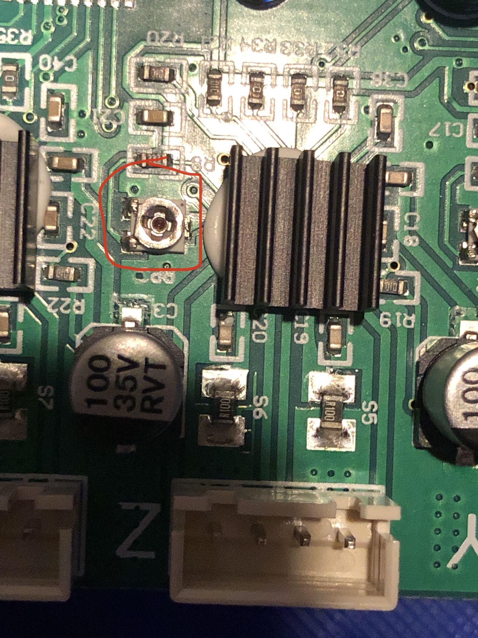
The first thing to do is to find the R-sense values of the driver boards you are using. It might be documented. Or you read the resistors off the board. Here is a site that translated the code on an SMD resistor to a value.. There are a number of sites that walk you through setting the vref, but the starting point needs to be the R-sense value. It is likely to be one of the three R-sense values I list, and if so, I give your the V-Ref value for the current setting that is approximately the value that Ryan uses in the firmware for other drivers…
So if your R-sense value is 0.05, your V-Ref setting of 0.7 is beyond the current limit of your stepper motor. But if the R-sense value was 0.1, your value of 0.7 would just about be right.
Are there any vref settings in marlin I might have missed?
Not all driver boards can set their V-Ref from firmware, and the A4998 appears to be one of them, so you are stuck doing it manually.
So the ‘try it and see’ approach doesn’t seem to be working here, so I’d suggest dropping back to the simplest thing that works and then make small changes.
So if you hook a single bare stepper up to the driver (with nothing connected to the shaft) and set the Vref to 0.5V, it works fine, seems to move smooth etc. What happens if you try applying a load while it’s moving (just trying to ‘brake’ the shaft with your hands, for instance)? What does it start doing under the same conditions as you start to raise the current limit on the same axis?
That’s the path I’d recommend following as it removes the most assumptions about other things working fine or not.
Once you’re at that point, you can check all the different axes and all the stepper motors and verify they’re all acting as expected. Then wire the steppers in series as you think they should be and verify that they move as expected (one rotating counter to the other etc.). From there, if you put it on the machine and start seeing issues, it might be worth looking at other potential causes, like something binding in your X/Y/Z movement, etc.
stepper and still had problems, up over the .7 vref.
This concerns me. I expected a lower R-sense and you were just pushing too much current. Maybe Jono is right, and you want to approach it by how the steppers behave.
As for R-sense and V-Ref, according to the docs, the calculation for v-ref (assuming 0.85A current setting) is:
I wired the stepper motors directly to the board and rotated the axis. They rotate as I would expect. I am able to pinch the shaft and make them skip. There is a difference between the 2 voltages, harder to stop on the .86 vs .59 vref but it isn’t a night an day difference. I think I’m gonna remake my wiring. I think I also need to look into axis movement and how much resistance there should moving it
If your steppers and motor are perfoming properly, I’d think it should be starting to get difficult to have them skip by holding them, but I haven’t tried with mine.
If it seems like that’s all working, I’d try turning them up further. The driver is 2A max and the steppers are rated for 1.7A, so with 0.1R sense resistors that would be around 1.4V. Running them at that for a little bit might should work fine, the steppers should get warm and will get pretty hot eventually, the heat-sink on the stepper driver should get warm as well but they should stay rotating and not jitter or cut in/out. They should be pretty difficult to stop at that point, I’d think, as a 40Ncm stepper should be exerting 4kg/9lb of force tangentially on a 20cm/0.8" pulley.