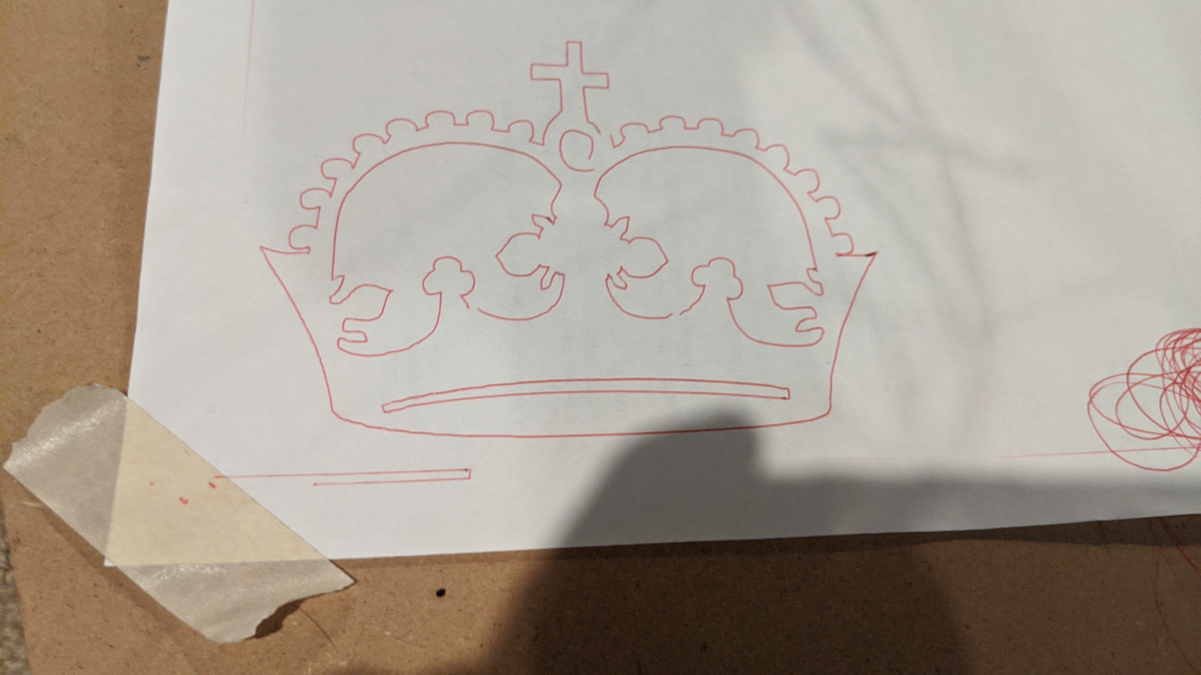
Hi everyone, I just finished(lol) my build and when through the estlcam basics, made the crown and printed it, and it looks like garbage. Any tips on how to proceed would be very appreiciated.
Thanks
Hi everyone, I just finished(lol) my build and when through the estlcam basics, made the crown and printed it, and it looks like garbage. Any tips on how to proceed would be very appreiciated.
Thanks
Going out on a limb and saying the pulleys on your motors are loose. Check the screws and make sure they are tight, and use loctite if you have any, or just tighten them down good and snug.
If that’s not it, then grab the router and tug it back and forth in the X or Y direction, firm but not hard, like 2 or 3 lbs of force, and look for what moves and what doesn’t. Somewhere you will find a joint (belts count as a joint) that is looser than it should be.
Also, check the belt tension (pluck the belts…there should be some tension/audible sound when plucked), and was the paper securely attached to keep the pen from causing wrinkles?
And, are you using the pen holder, or just taping it to the Z axis? It may just be a problem with the pen mount. The ideal mount moves easilish in Z and is rigid in X and Y.
So I rechecked the gantry and it had some play, I snugged it up on the rails and a got a little better result. The paper is securely attached, the pen mount is solid. And with what I think are either over-tight or over-loose belts this is the best result I can get. It’s a little better, but there has to be something else that needs adjusted, right?
I am totally no expert, so take this with a pinch of salt.
Don’t understand why the crosses are out of alignment? Could the steppers be going faster in one direction than the other?
Have you sent it 200mm in one direction and checked that is what you get, then return it 200mm and see if it returns to the start point?
Try drawing large squares and checking the diagonal measurements are equal.
Or maybe is the entire rig out of square?
Also, you don’t need much pen pressure. The pen holder I have is sprung, so it keeps light tension.
What kind of pen some click pens allow the point to move like runout in a router also can you redrawing it rotated 90 degrees to what you are now?
It should definitely be better than that. Can you post some pictures of the whole machine?
Do you have a router? Maybe go straight to carving it in some HD foam and see if that is better. That will remove any doubts about the pen.
I’m with jamie here. It appears that one or both of the Y pulleys are not tight on the stepper. Cut a zip tie from the belts so you can adjust the pulley easily. Loosen both set screws and be sure to have the first set screw perfectly centered on the flat side of the stepper motor shaft as you tighten them.
AAAHHH!!!
Thanks for the help. I took off the gears on Y and carefully put them back on. I don’t know if doing that helped or cutting a smaller piece of paper and using more tape to hold it down did it or both, but it’s a little better.
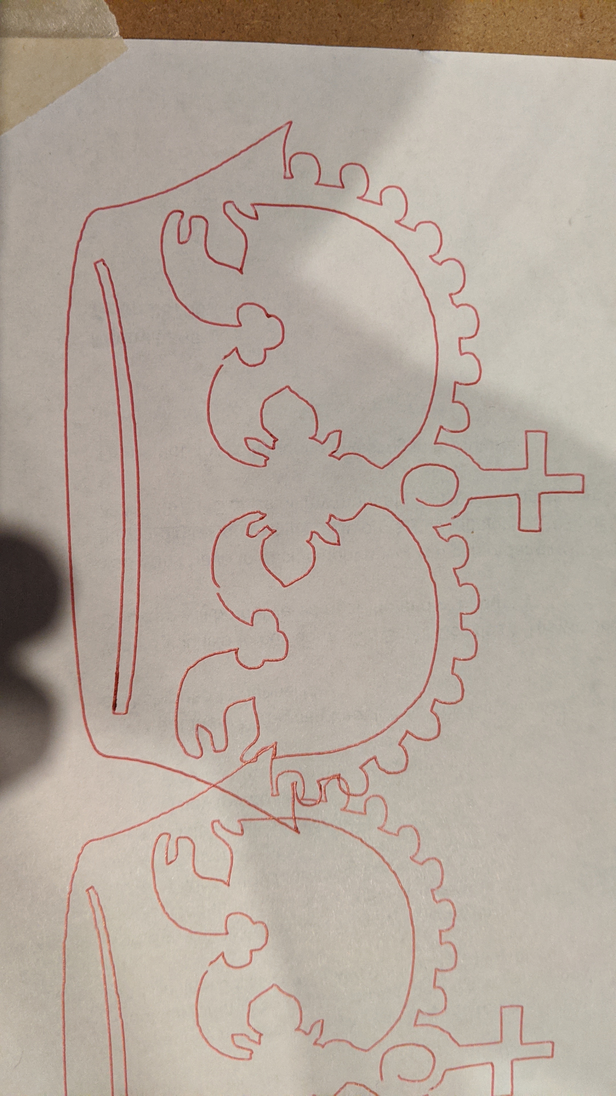
Rotating it 90 looks like this.
Rotating back to the same position as the first two pictures I posted looks like this.
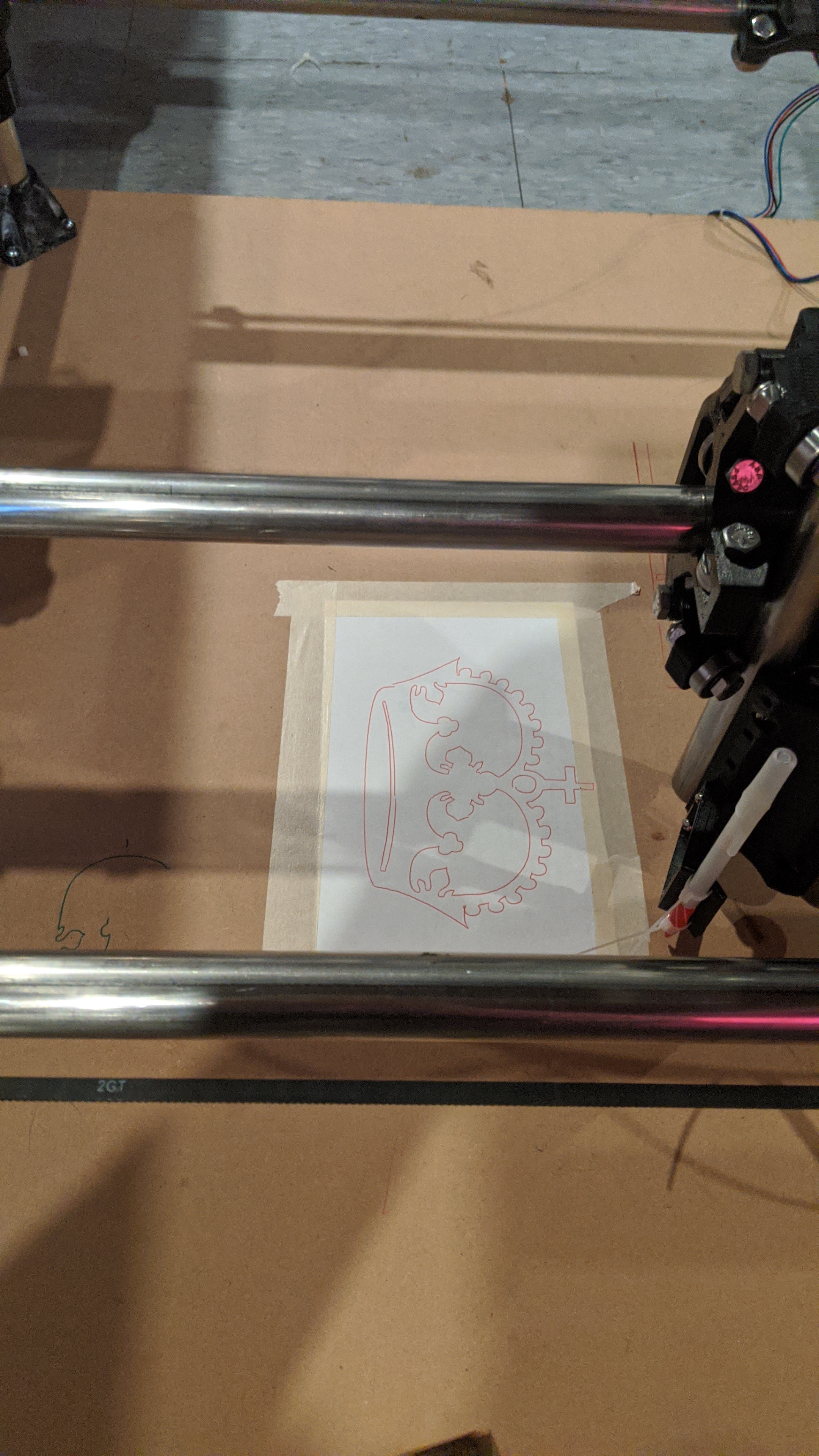
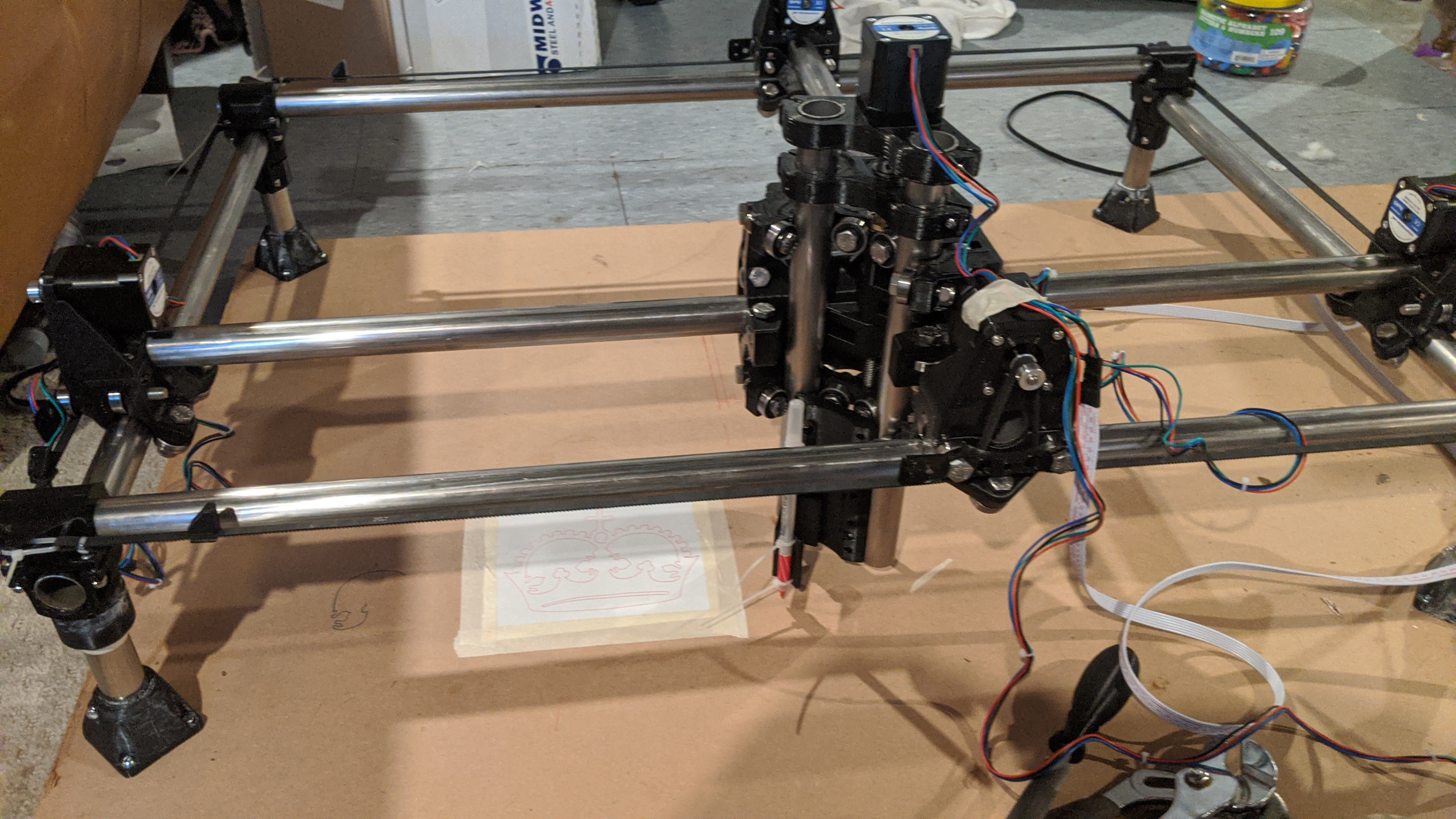
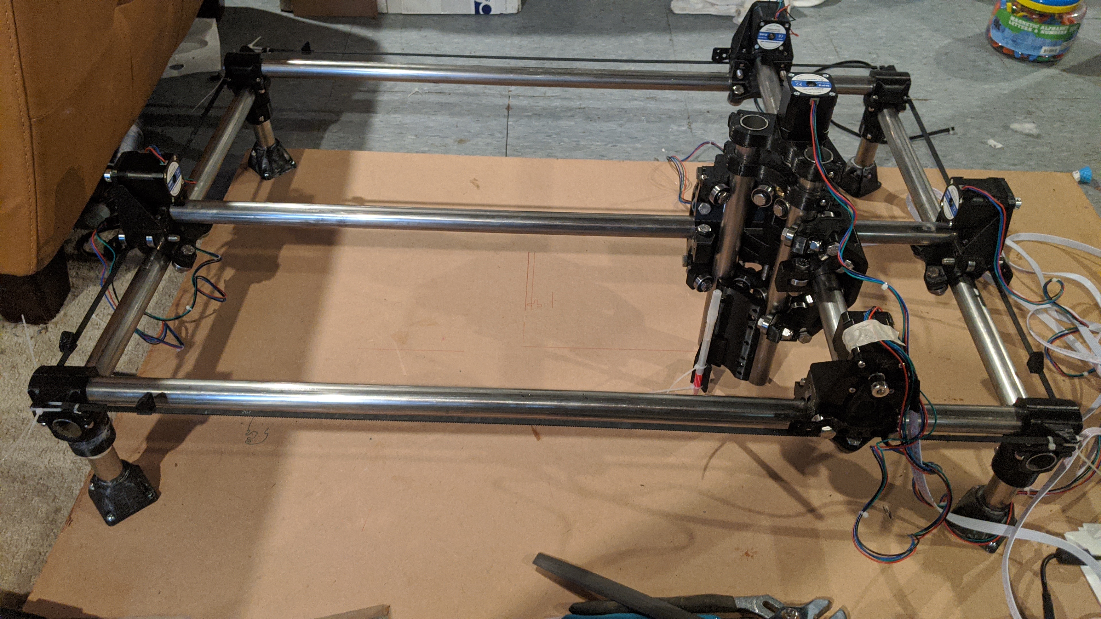
Here’s the whole machine picture.
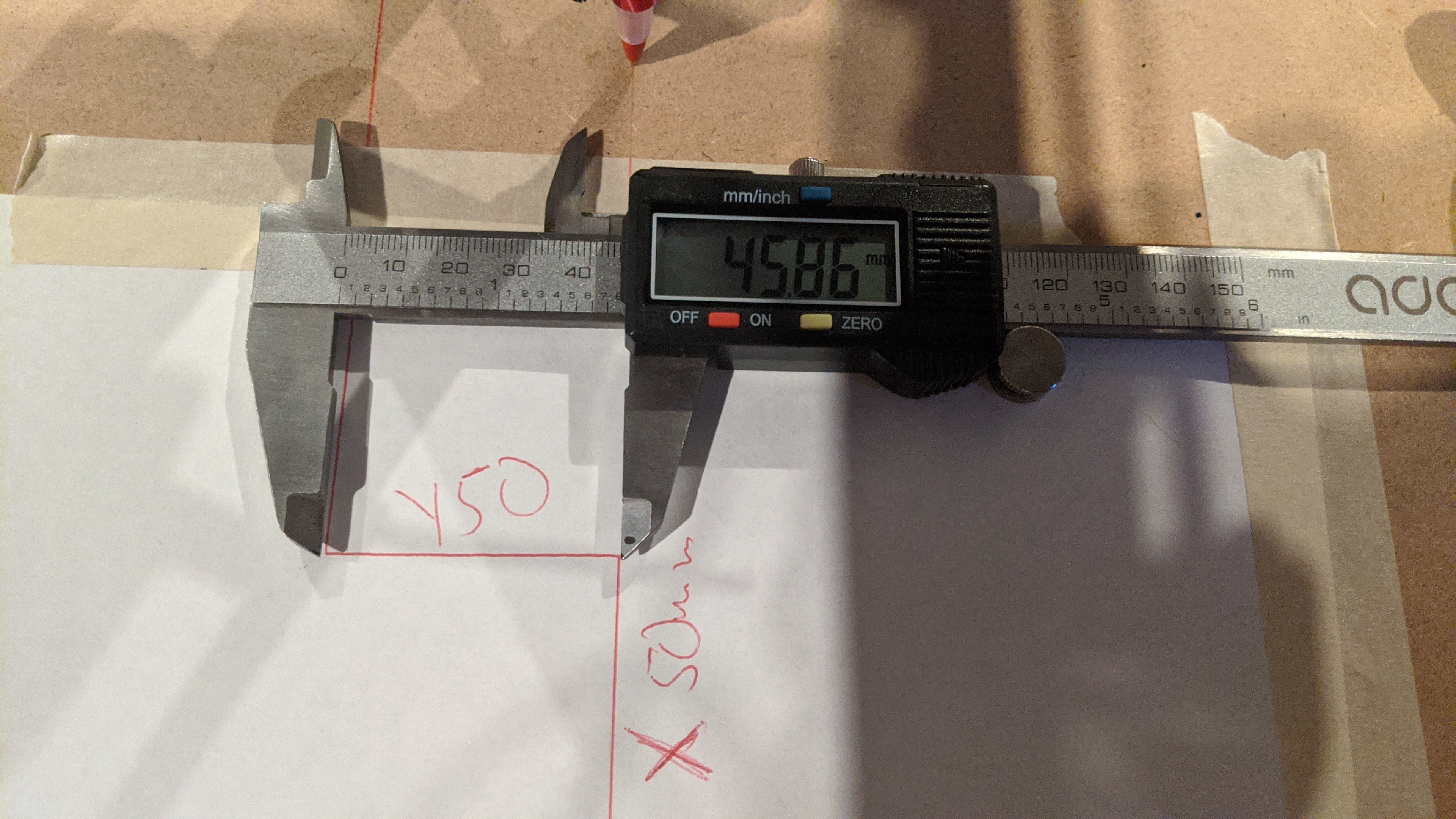
And finally, I ran the pen 50mm on the X and Y axis in both directions a few times and got just about 49.9mm for X and kept getting around 46 for Y. This is obviously a problem, but I’m not sure how to fix it. Can you adjust the steps like calibrating a 3d printer?
I’m probably not going to be much help, but I’m interested because of how it’s both consistent (same in multiple drawings) and inconsistent (left to right in individual drawing) I was going to say check simple things like making absolutely certain your frame is square and there aren’t any burrs on your tubes or debris on the bearings, but that doesn’t line up with how it’s inconsistent. I was going to say check your feed rates as it looks like it’s losing steps but that doesn’t make sense because of the consistency between drawings. I’m stumped. I guess I would try reversing the leads on the X or Y axis (one axis at a time) it isn’t going to fix the problem, but it might give you a hint of information that may help find the problem. Good luck, it’ll be worth the effort once you get it dialed in.
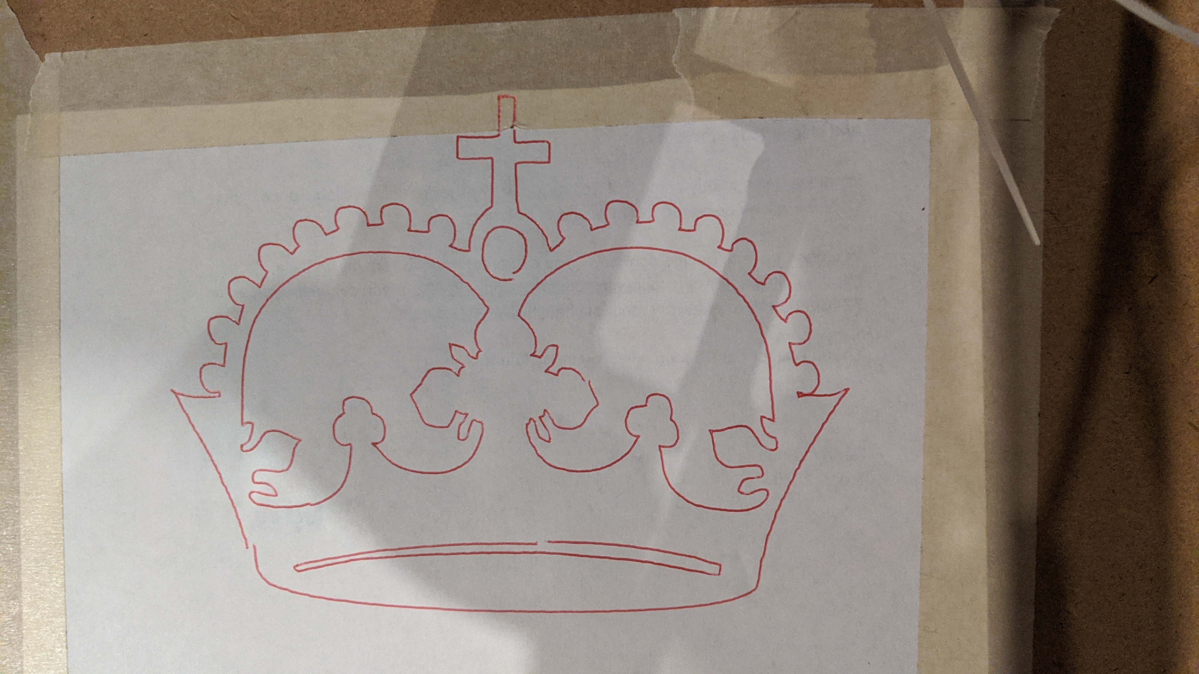
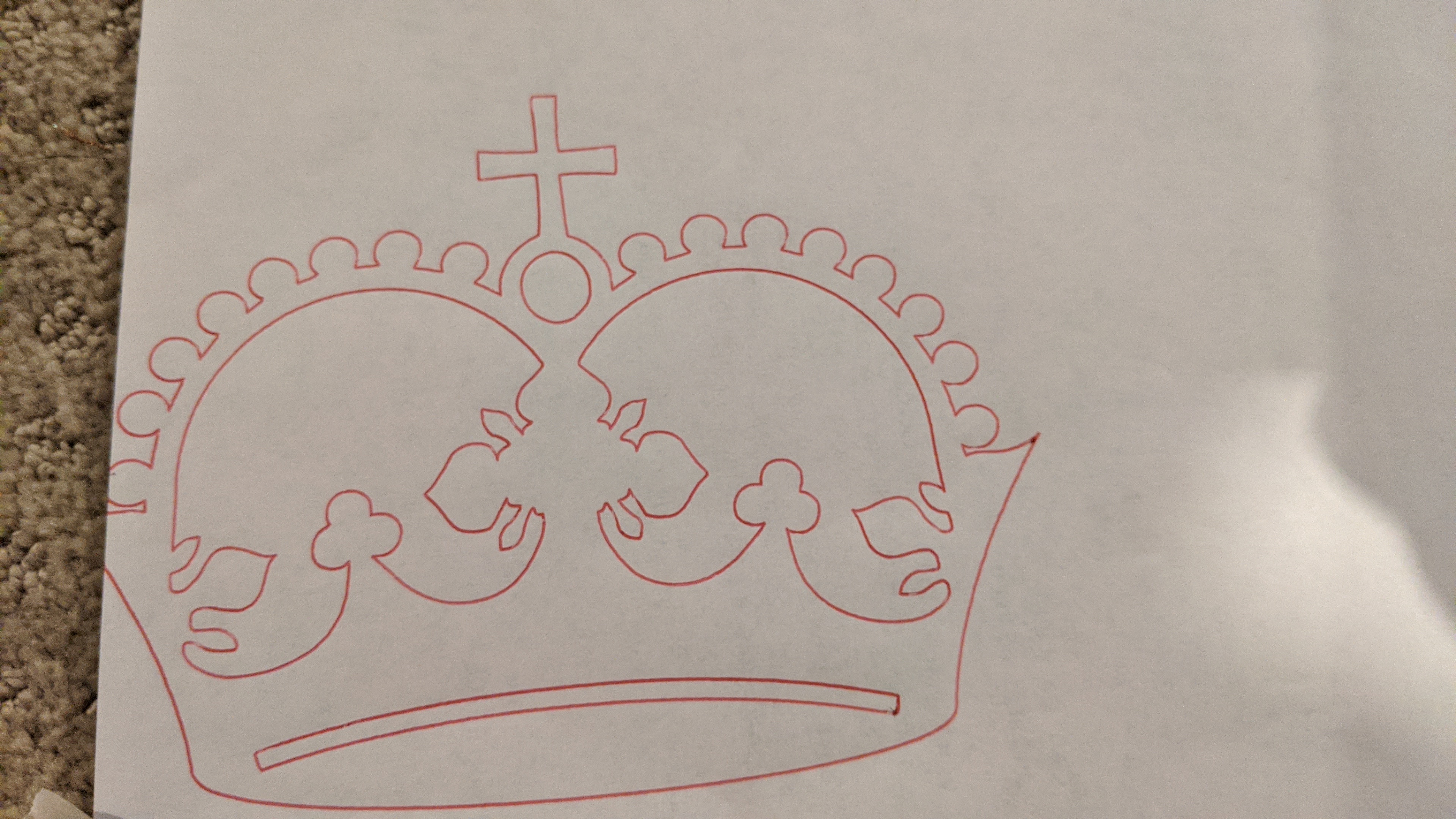
It looks like you still have backlash in both X and Y. I’d say Y is slightly worse than X but both need improvement. I am looking at the cross on top of the crown. The top limb and the bottom limb are not the same width, and the left and right limbs are not aligned with each other. The difference in width of the top and bottom indicate the backlash left-to-right, and the misalignment of the left and right limbs indicate backlash top-to-bottom. Usually left-to-right is X and top-to-bottom is Y but in your rotated example they are the other way. (And it looks like the rotated one is the one where the pen drew on the tape a bit.)
I see you have the endstop blocks installed but it looks like you haven’t installed the switches yet. Is it possible you have the motors connected to five stepper drivers but you don’t have dual endstop firmware installed? This would leave two of your motors unpowered.
Engage the steppers and grab each of the motors and try to push it along the side rail. Just a few pounds of force is enough, no need to put your whole weight into it. Push it both ways and see if it moves. Do that for all four motors. This will also detect if a pulley is loose on a motor, although it sounds like you already checked that. If you have motors wired independently (not in series) and you have the non-dual-endstop firmware then two of the motors will easily move a bit.
Your construction looks solid as far as I can tell. The dual wiring seems most likely so try wiggling motors first and if that’s not it we’ll consider what else.
Ah, I didn’t get to the dual endstop firmware yet! Thought I could wait until I had it all squared up and working properly before I got into that. THANK YOU.
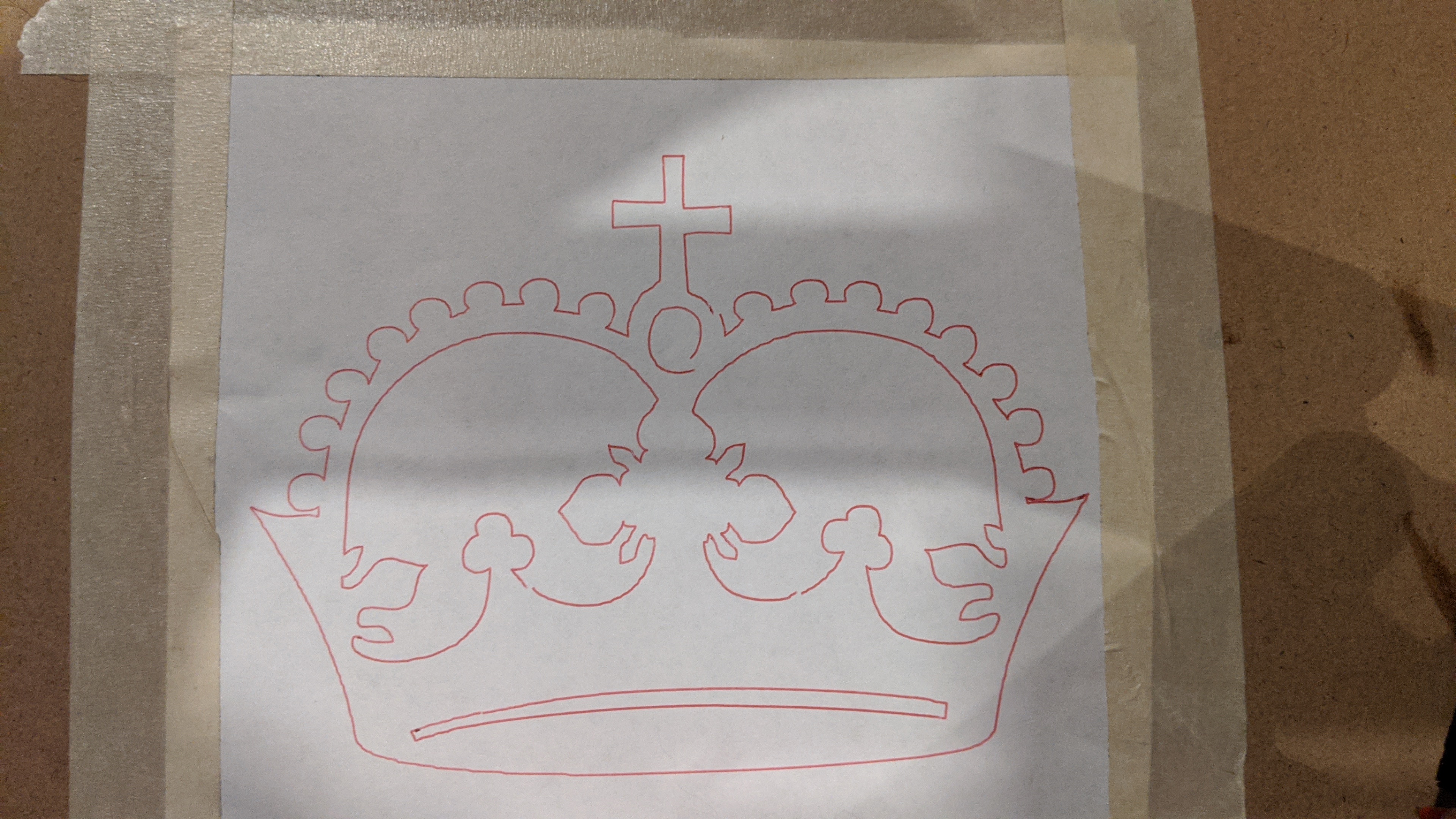
There we go! That is what the crown should look like. Nice spot Jamie.