I’ve just received the last parts needed for my lowrider: the gt2 smooth idler pulleys and toothed timing pulleys. To my surprise the idler pulleys are taller bu 0.8mm than the parts listed in the parts list: the linked amazon page has a drawing showing them at 14.2mm mine are 15.0mm tall.
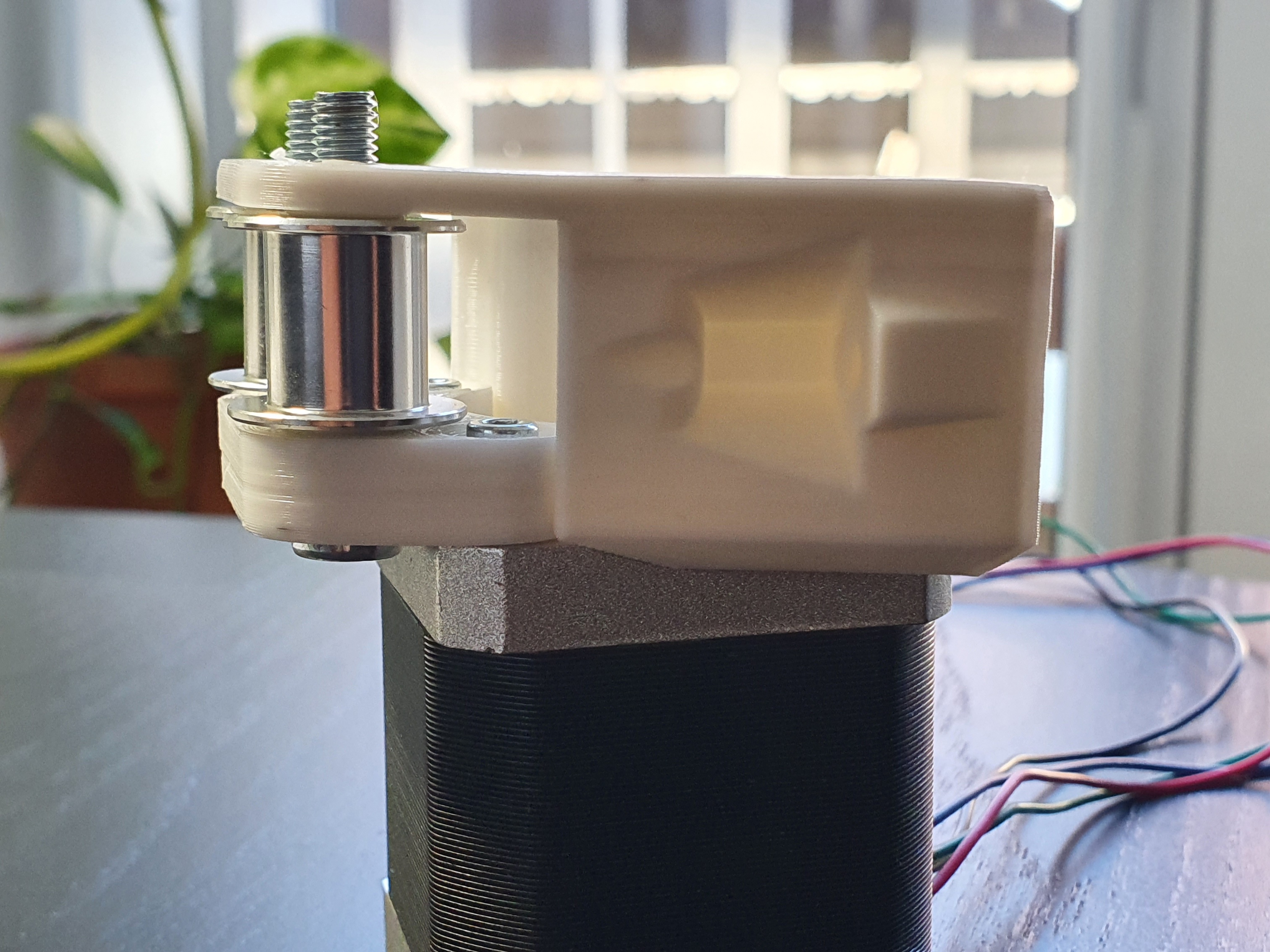
Anyone else had this issue? The is a solution for the motor on the base-plate that doesn’t involve modifications to the standard printed parts (a printed spacer between the large piece of the bracket and the motor) but for the side motor mounts it would be best to modify the bracket. I guess elongating the holes would also work but it doesn’t look right …
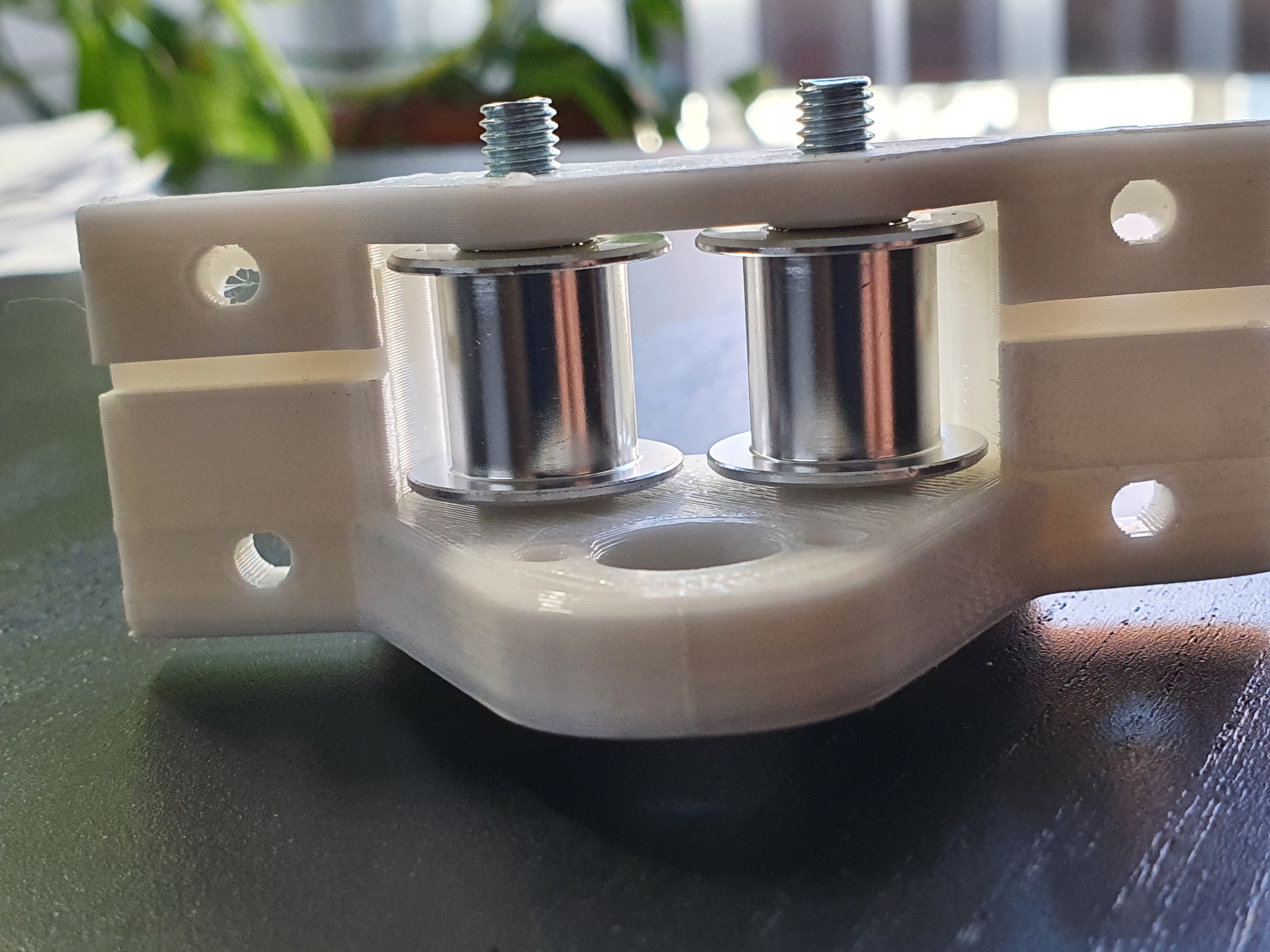
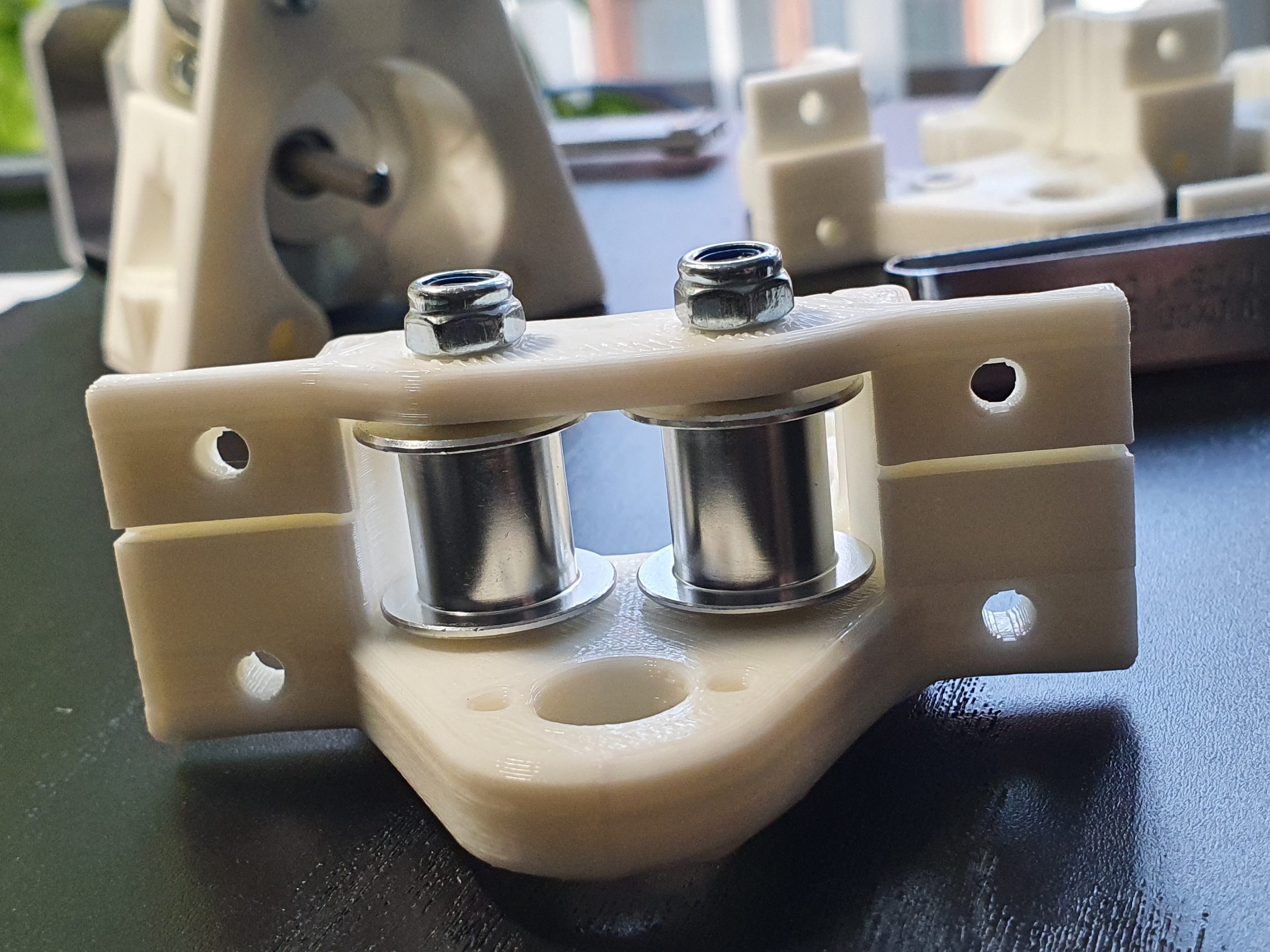
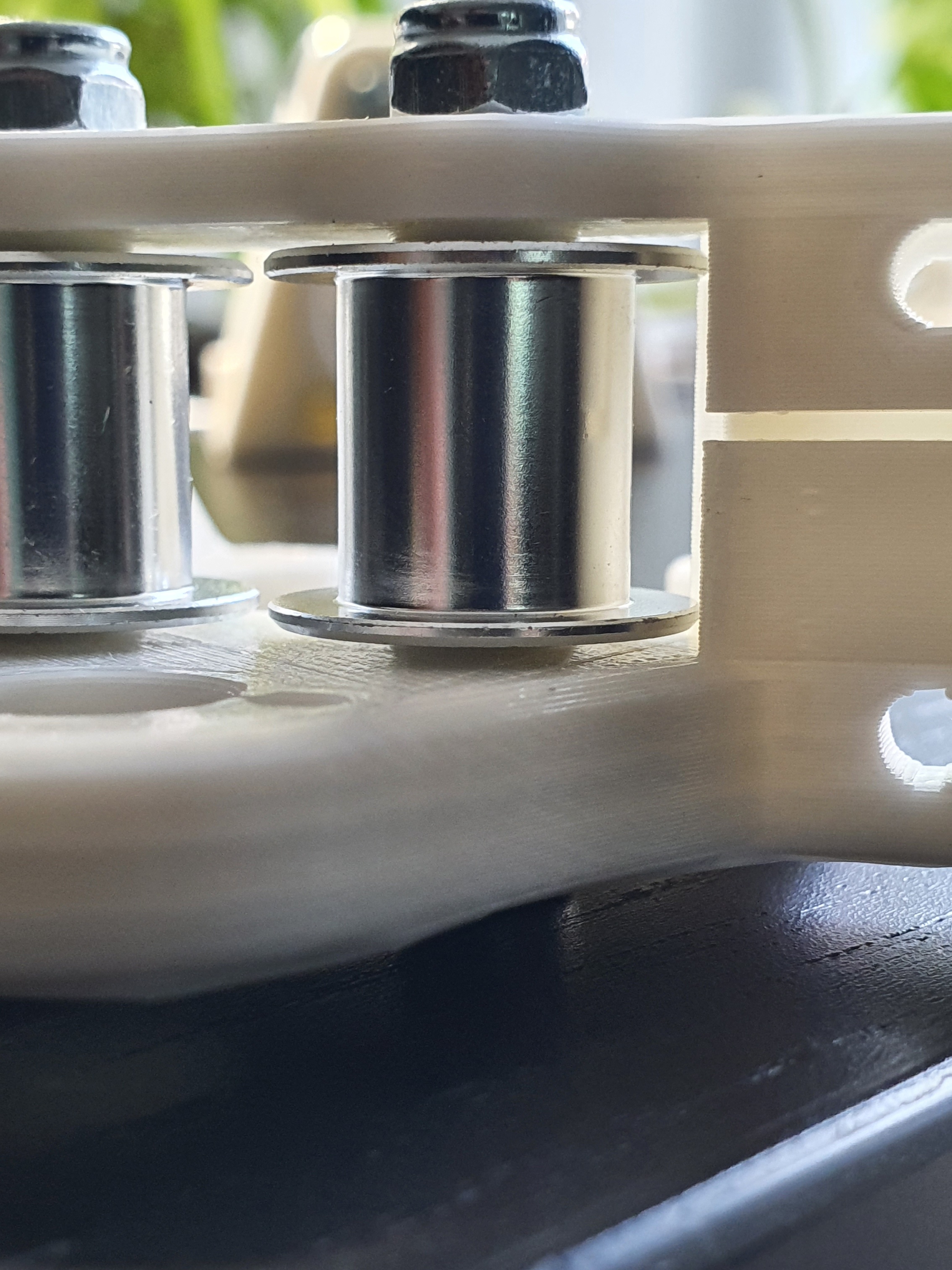
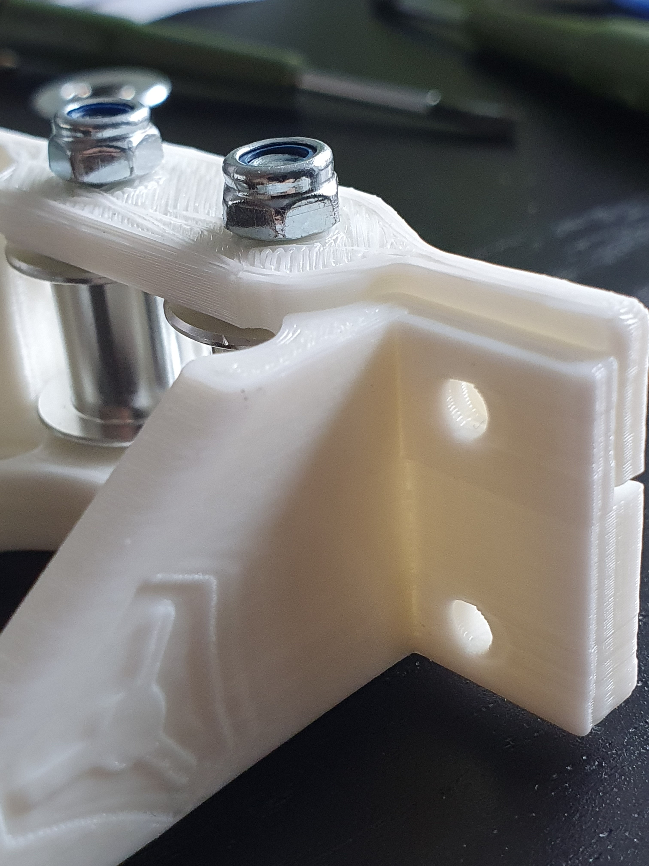
It gets worse: the “bumps” in the printed parts that are supposed to contact the inside of the bearings are so wide that the idler rests on them altogether. The diameter of these raised areas (at lest for the idlers I got) should be less than 7mm and i measure more than 9mm (9.5 ish) on the standard printed parts. I’m amased that the idlers are so diferent.
Can I ask here for customized parts rendered from the parametric cad files or my only options are to reverse engineer / design new parts from scratch or get compatible idlers?
Do you have a CAD that can work with STL files? Fusion 360 can do this. From there you can modify the parts (albeit very time consuming). However, the easiest solution and the least costly in terms of time and money would be to order another set of idlers.
I don’t have the skills required to modify starting from the STL files. I’ve tried using FreeCAD and got to a nicely looking solid object but not much further. From that attempt I see that the “bumps” are 8mm in diameter on top and wider at the base. I’ll see if I can learn how to modify that object
The bumps measure 9.5 at the base, 0.85 high on a draft printed part so I assume the measures above are correct. The least amount of modification to have the bumps seat correctly into the bearings of these locally sourced idlers would be to reduce the base of the bumps to 8mm. The resulting 7mm upper face would be perfect for supporting the inner race of the bearings.
In order to gain 0.8mm clearance The Y top part would have to have the wings taller and the holes shifted by 0.8mm. Also X2_Idler would have to be 0.8mm thinner.
I hope I have been clear and thank you so much for the kind offer.
Since everyone buys these things from china I’m sure there will be others potentially benefiting from these variants. (The name I bought them from a local shop was “GT2 5mm type 20 no tooth for 9mm belt”)
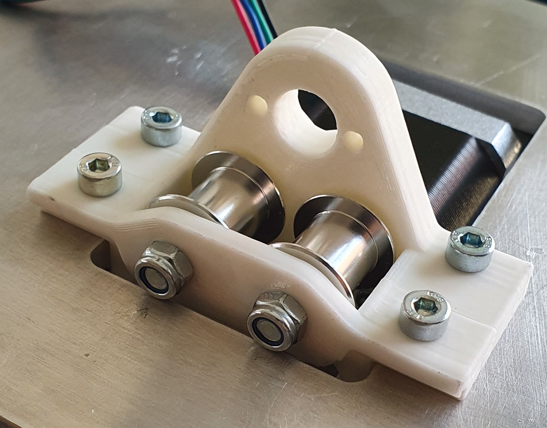
The thinner bumps do their job very well, the idlers rotate nicely. The total height is still off by 1mm (measured by feeler gauge after snugging the idlers in their final position). What was the height of these idlers in the original BOM ? The ones on amazon are 14.2 (so 0.8mm shorter than mine) but it looks like the parts have been originally designed for even shorter ones. My delta printer produces almost 0 error on Z and less than 0.5% on X and Y in my geometric accuracy testing
The top part bends enough so it is usable as is, a version with even taller wings (and matching holes position) would fit even better. Y_Bottom would also benefit for some extra height in an ideal world:
I revised both the X2_idler and X2_plate with smaller pads and extended X2_plate 2mm on the motor end. They are uploaded now. Let me know how things work out for you.
Can see it’s done now but RepiterHost (and other 3d print software) allows you to scale 3D prints. Each axis can also be scaled separately. So you can load in then “stretch” the Z axis to make it taller. Typically I print ABS and have to enlarge by 2% as the print shrinks as it cools. May require a couple of tries but you don’t have to edit the part this way.
Thanks for the suggestion, a valid one for uniform scaling on at least one axis. In my case specific features needed to be enlarged others just moved. For example a stretch on Z would have resulted in oval holes that would have been undersized at the location of the bolt.
@tgm022861: the X2 fits very well too! On the Y the idler nuts touch the Y flat part but it fits without modifications, I was lucky. Problem solved!
It looks like you needed to remove some of the wood along the edge. I would probably have used a round over bit in my router table. Of course a flat file would work fine. Or even a round file for a more targeted removal of material.
Anyway, I am glad it worked out for you.