TFT35 E3 V3 screen box

Kinda out of place here but I have needed to make a tft case for a loooooong time.

Could I ask for a couple beta testers to give this a shot. This has a stand and /or LR attachment clip.

This needs two 6-32 1/2" or longer screws, just like the old case.

I did a full test print, then just made a few edits. So technically these are untested files but I believe them to be ready to go.

TFT35 E3 CASE.zip (163.8 KB)

1 Like

Man. My printer is down at the moment, or I’d print one up.

2 Likes

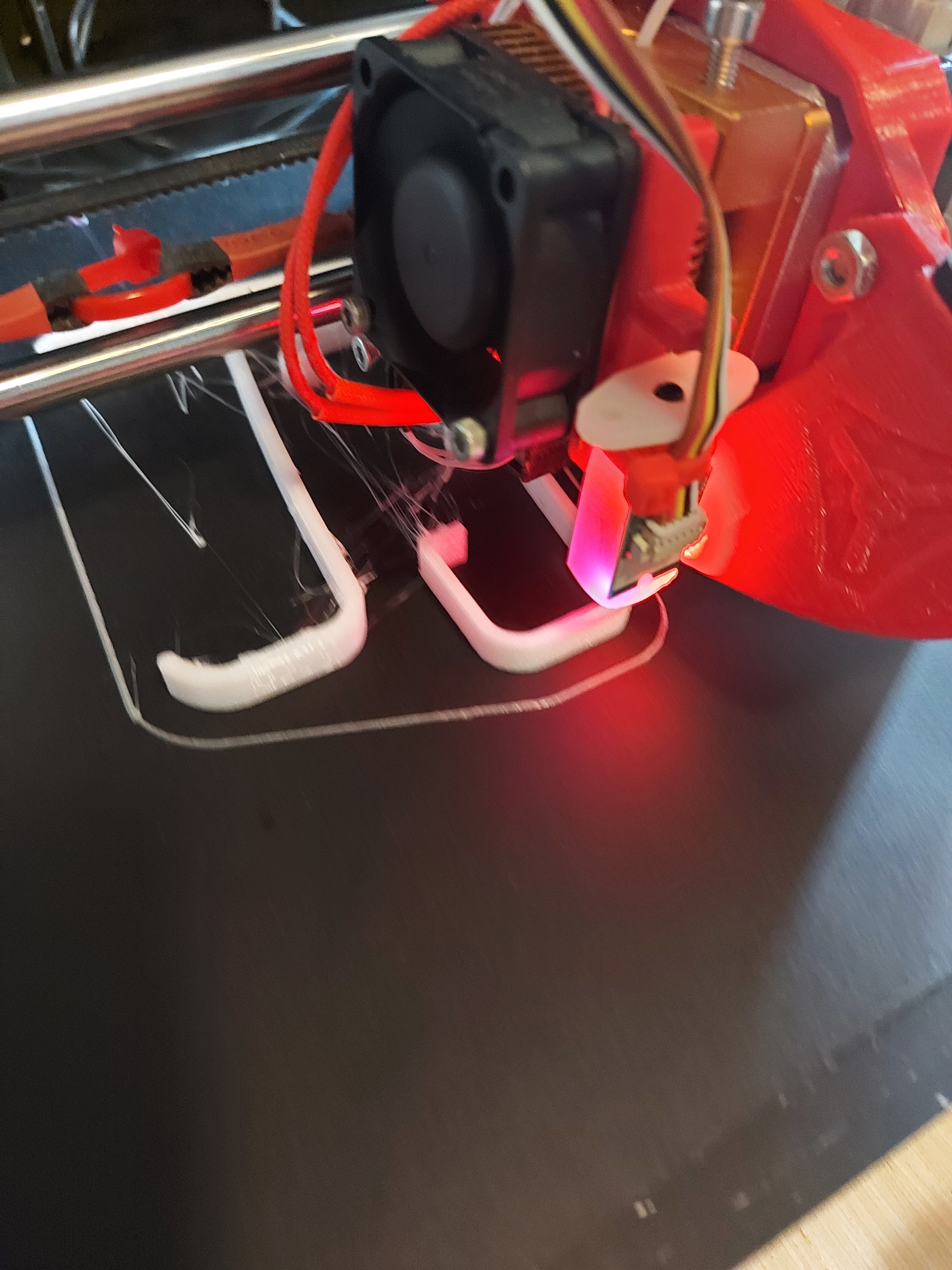
Thanks Barry. I printed another, my slicer settings still seem off, ugly surface finish on my prints. The case seems good to go after I move that little center button hole over a few mm.

Moved the center hole over a tiny bit.
TFT35 E3 CASE.zip (163.8 KB)

Added to first post

1 Like

I guess I’ll live with it a bit off… Already about 40% of the way through printing.

Edit: I really need to tune retraction on my MP3DP… It’s drooling all over.

2 Likes

I like it. Surprised the knob LED’s work so well.

2 Likes


New 2.5D project coming soon, gotta make matching poplar caps for the new LCD, too.

Edit: my LEDs are turned off, but work fine.

2 Likes

I have a box of Baltic birch scrap triangles. Perfect for end caps!

1 Like

https://www.prusaprinters.org/prints/74330-tft35-e3-v3-case

2 Likes

Just in case you want to add wifi :wink:

Don’t hate me Dan, I just put up version 2 of the case. If editing the STL was a pain let me know and I will make some step files.

No problem. I like the new version.

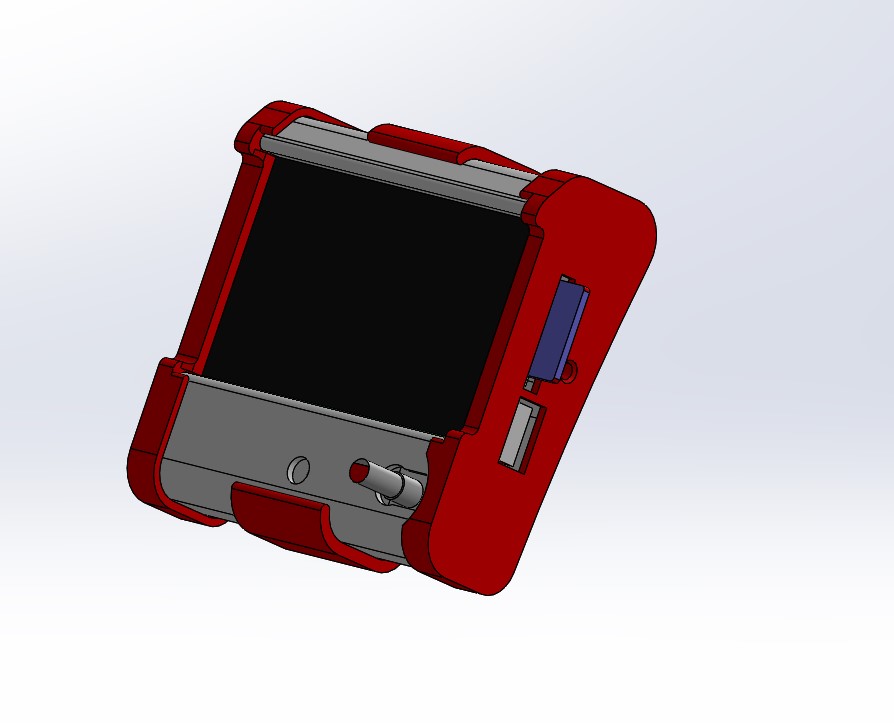
This will be a bit more work for the edit, but it’s a pretty simple thing, since I just needed to put a hole in it. It’s a 3.5mm by 14.5mm slot that centers 10mm “down” from the SD card. I think it’s 1.5mm from the edge of the card itself, I went even (maybe .5mm back) from the edge of the SD card hole on the one I did.

If you want to do a quick sketch of that, I can make one, or I can just upload the step files to the prusa printers page and you can do another custom one.

I don’t think I have any more of the wifi’s here, at least I can’t find the one I had on my desk. It has to be here somewhere, though.

I’ll look.

The PCB just sticks straight to the side from the 8 pin wifi header on the board, so it’s not difficult to model from the TFT board. That was where I took the measurements for where the slot centered in the first place.
TFT35 E3 Wifi
This is an SVG from my previous edit, and is the one I’m using on the LowRider.