Printed and Cut parts
If a part ends in V1, V2, V3, etc it just means it is a new or revised part. Always use the highest number if there are multiple.
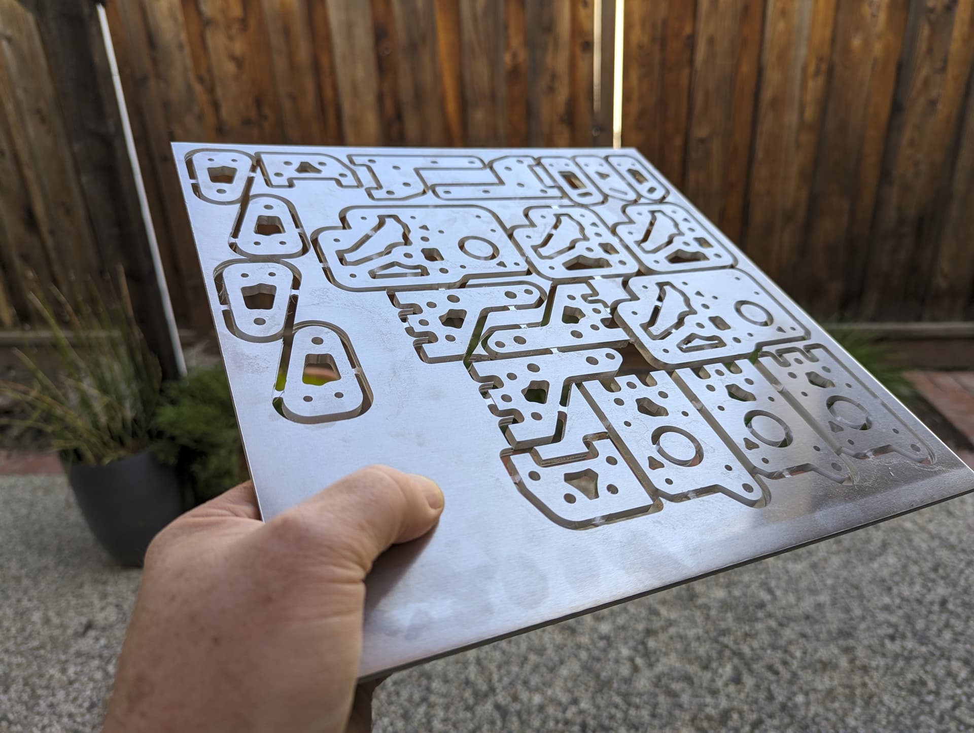
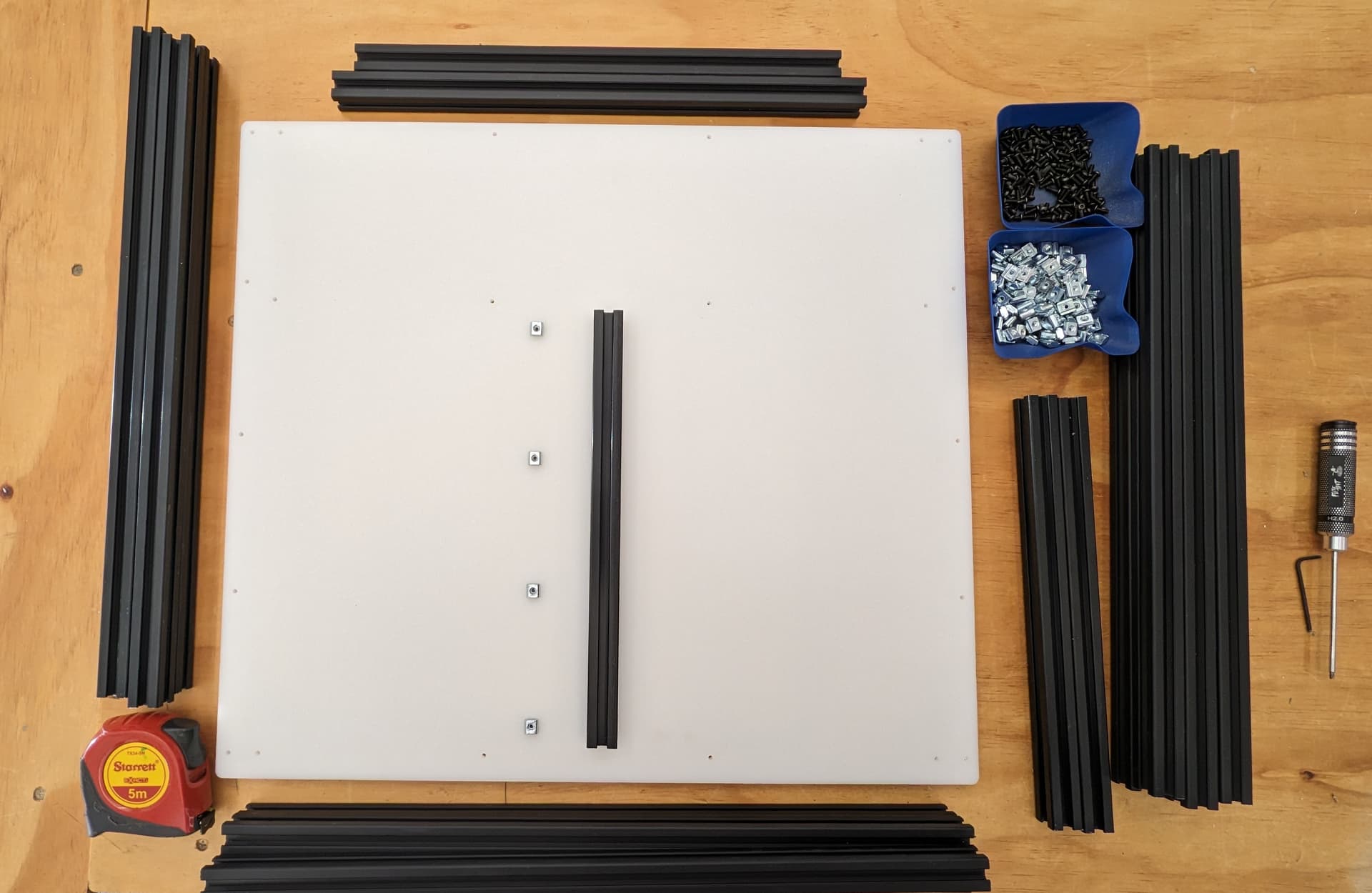
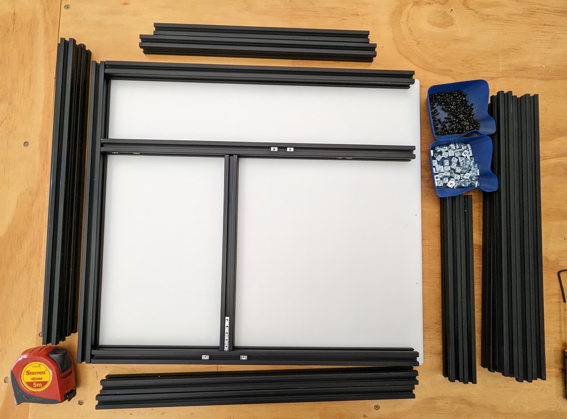
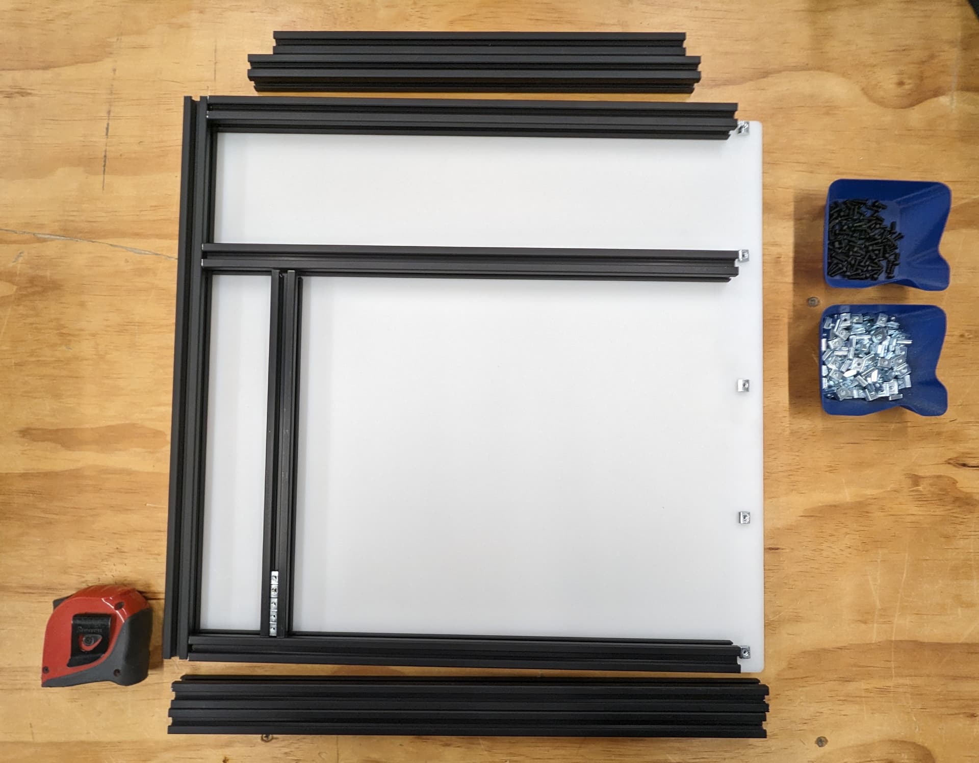
–Cut Parts–
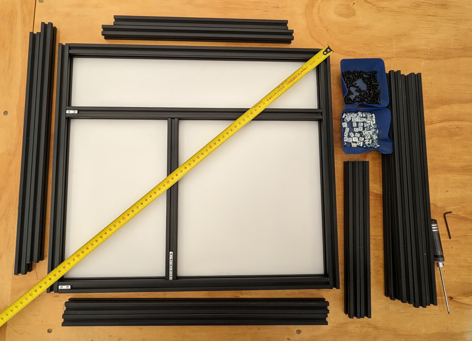
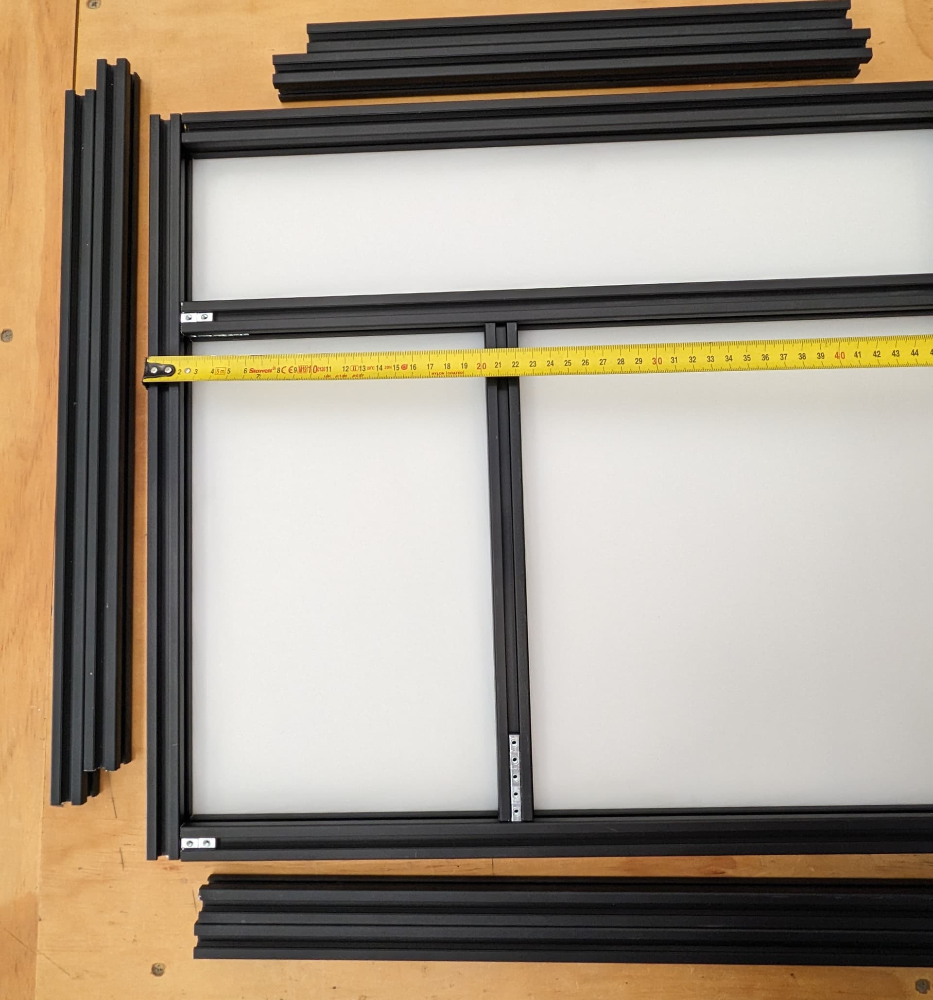
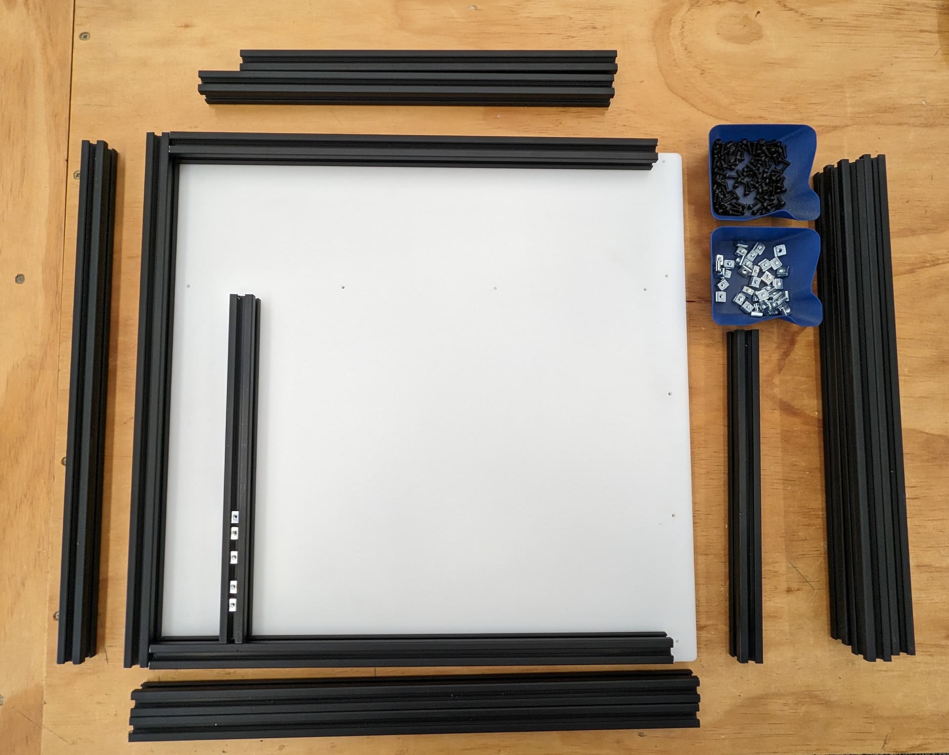
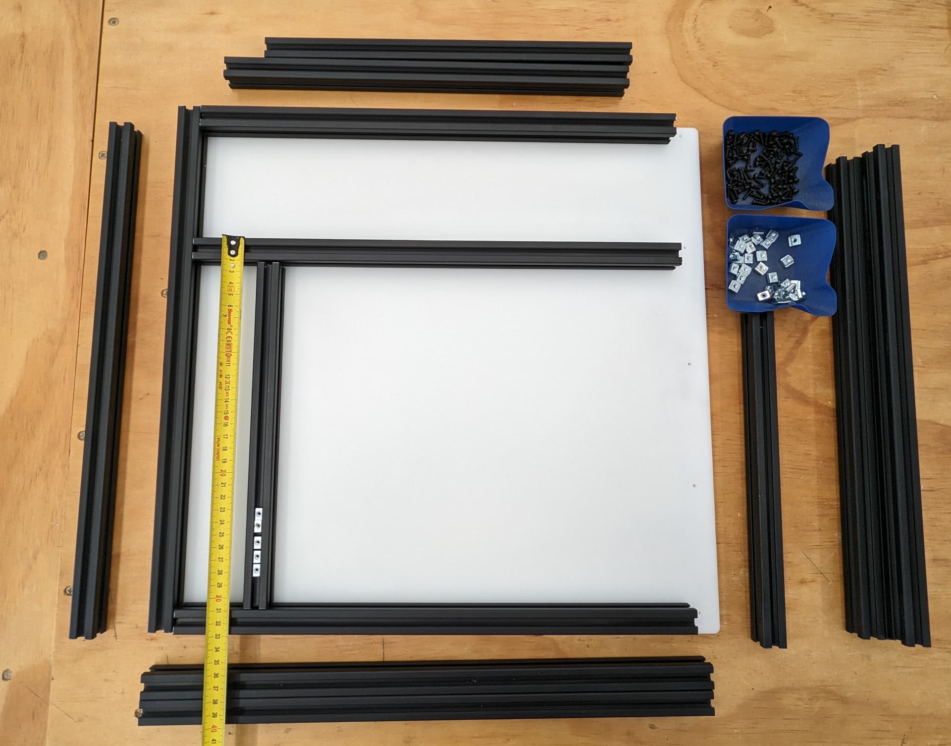
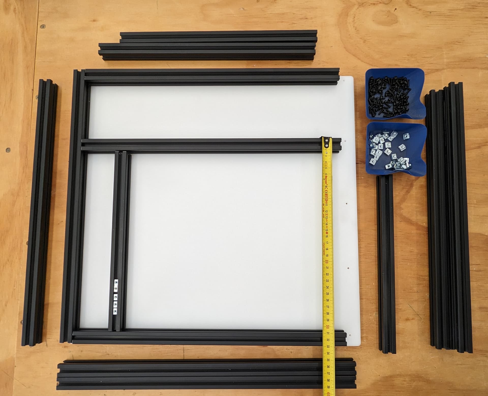
The Three Bed cut parts (Bed A-C) are the only parts that are size dependent. Make sure to set the correct build size before cutting these parts. 300X x 300Y is the default included size.
Qty 1x Bed A, B, C
Qty 2x Corner Stepper, Corner Top, Truck Rail, Truck Top.
Qty 3x Z Back, Z Front
Qty 4x Tensioner
–Printed Parts–
The Core parts depend on your build. You need 1x Top and 1x bottom. The Cad is linked below if you want to adapt your favorite extruder.
1x Core bottom H2 VS2 / Lite, or Hemera
1x Core top H2 VS2 / Lite, or Hemera, with Canbus mounting holes or a small terminal block holes / no extra mount
1x Y Endstop Holder, Z Bearing Mount, Belt Smooth and Wire
2x X Rail Nut Holder, Front Tension Spacer, Truck
3x Z Bearing Mount, Z Belt Upper, Z Lower Belt Holder, Bed Mount
4x Rear Spacer
6x Z Spacer
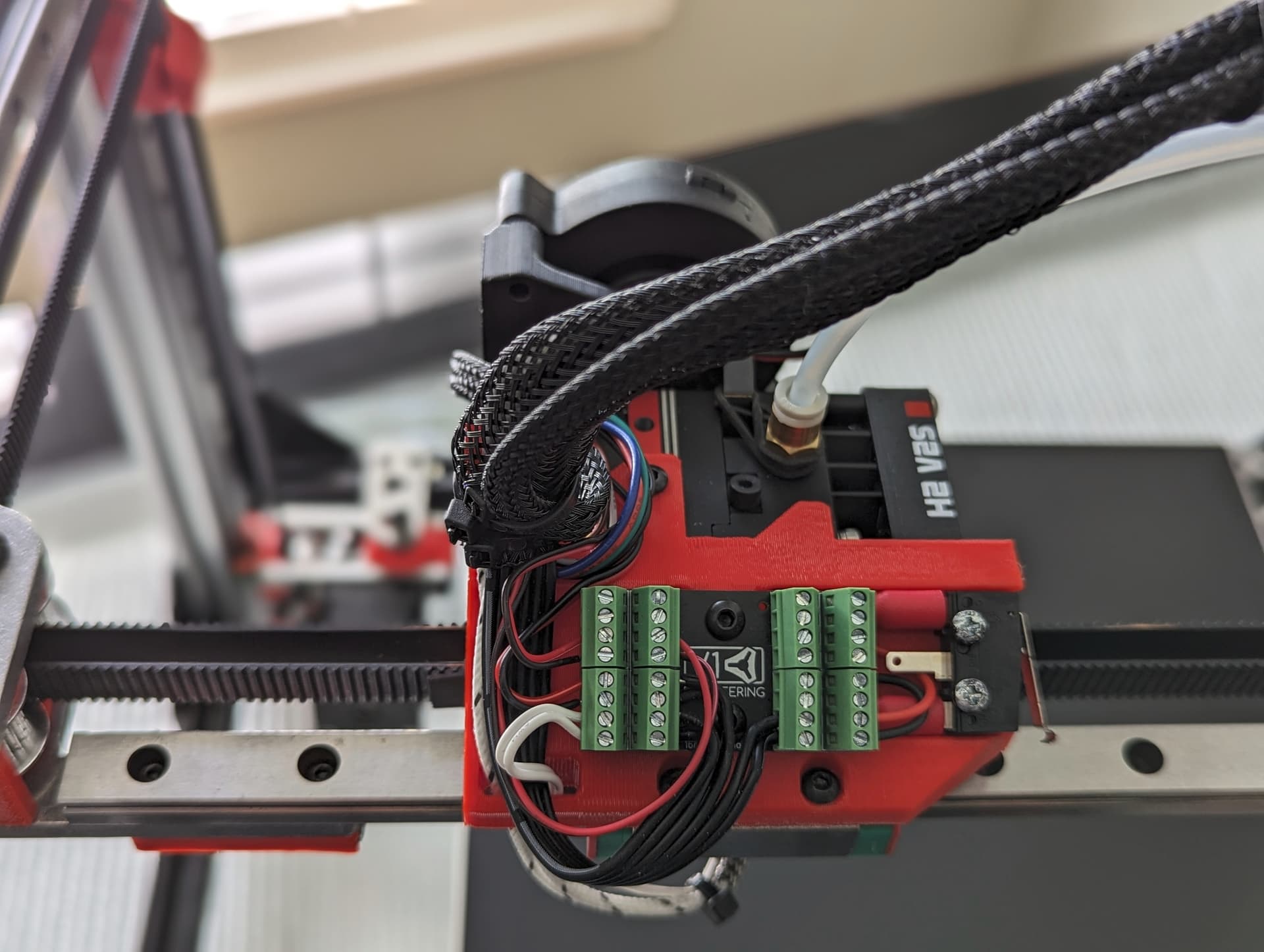
–H2 V2S–
Parts and hardware -Printables, MakerWorld, Thingiverse
-Hardware Needed for the Extruder
1x M3x16-25mm fan to mount
2x M3x10mm extruder to mount
4x M3x5mm ADXL and Probe
Bonus, printable Nozzle torque tool, From this page, How To Properly Tighten A Bondtech BiMetal CHT Nozzle. Highly recommend it.
CAD Help
CAD is here - Fusion
The three Bed cut parts (Bed A-C) are the only parts that are size dependent. Make sure to set the correct build size before exporting / cutting these parts. 300X x 300Y is the default included size.
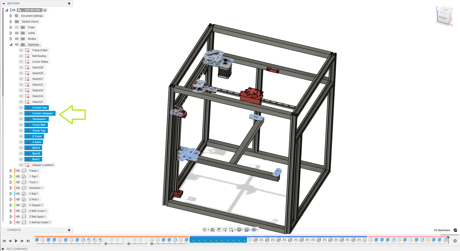
If you want to export your own DXF’s this is where you find them.
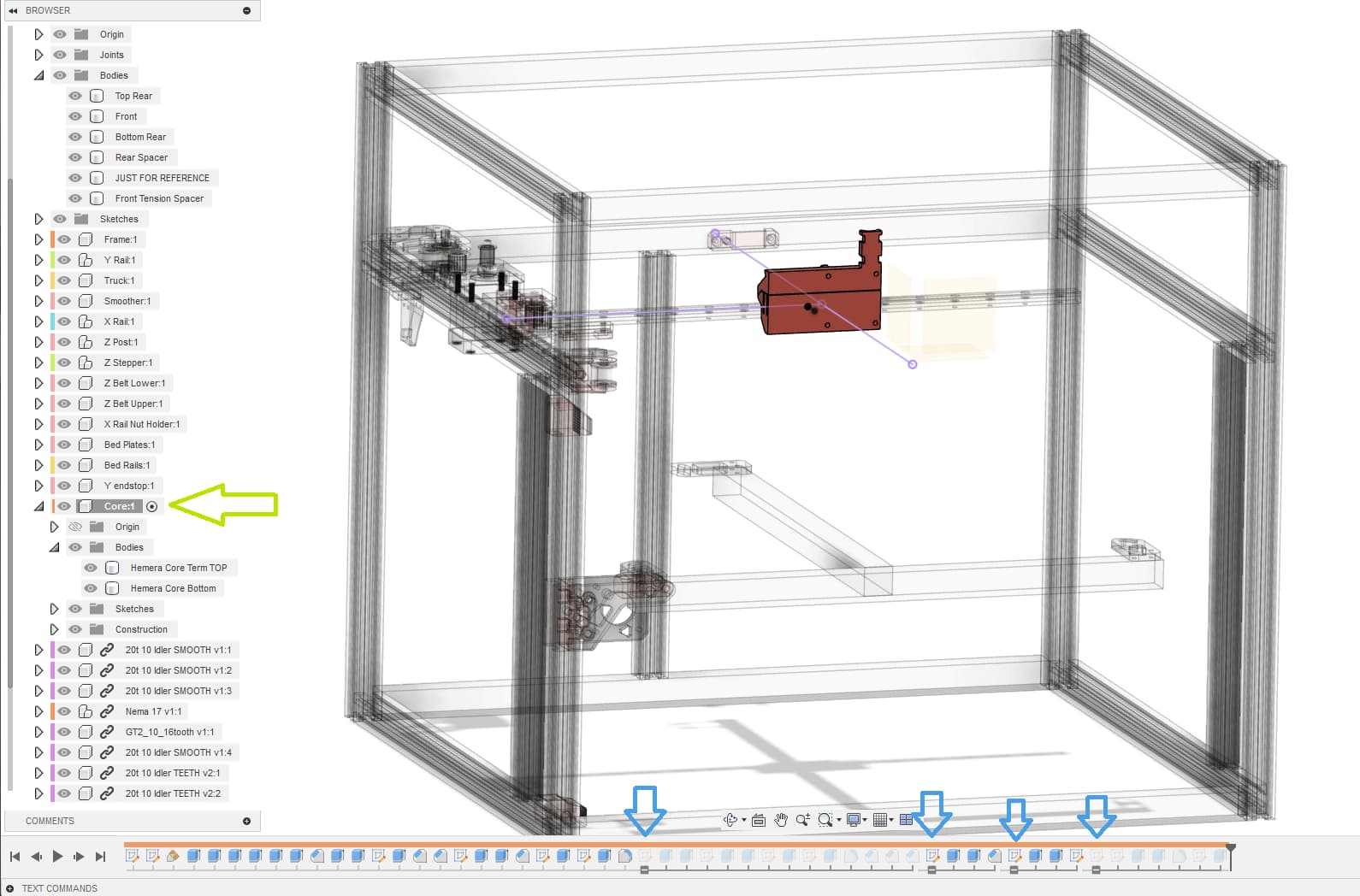
If you want to change the Core type you will find suppressed groups in the “core” you can suppress and un-suppress them to change the extruder type, or to make your own.
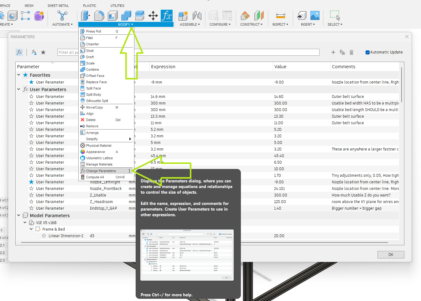
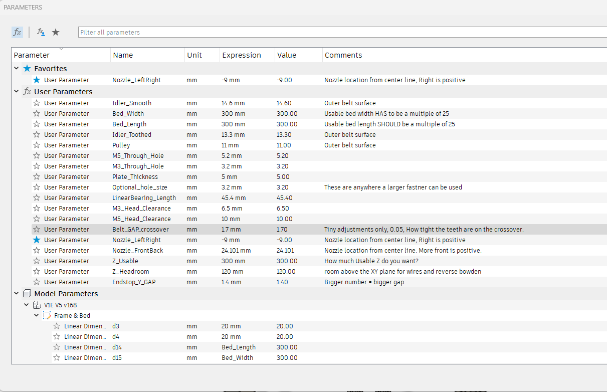
This is how you adjust the model. Open the modify menu, Change parameters Menu.
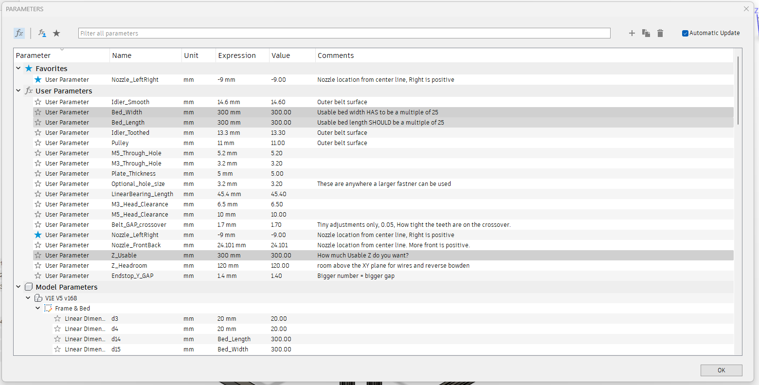
These three settings are how you adjust the size of the build. Z is not exact as it depends on the hotend you chose but it should be close.
Note- The CAD will fail if you go up and down in size. Make one edit and it should be fine. If you have an issue, start fresh.
This lets you adjust the hole size for the Plates to frame. I was asked to allow for M5 hardware, this is where you do that, you will need to export new DXF files for the corners and tensioner parts.
If you want to make the Belt have a tighter or looser grip on the core bottom or Z top pieces, you can change it here.
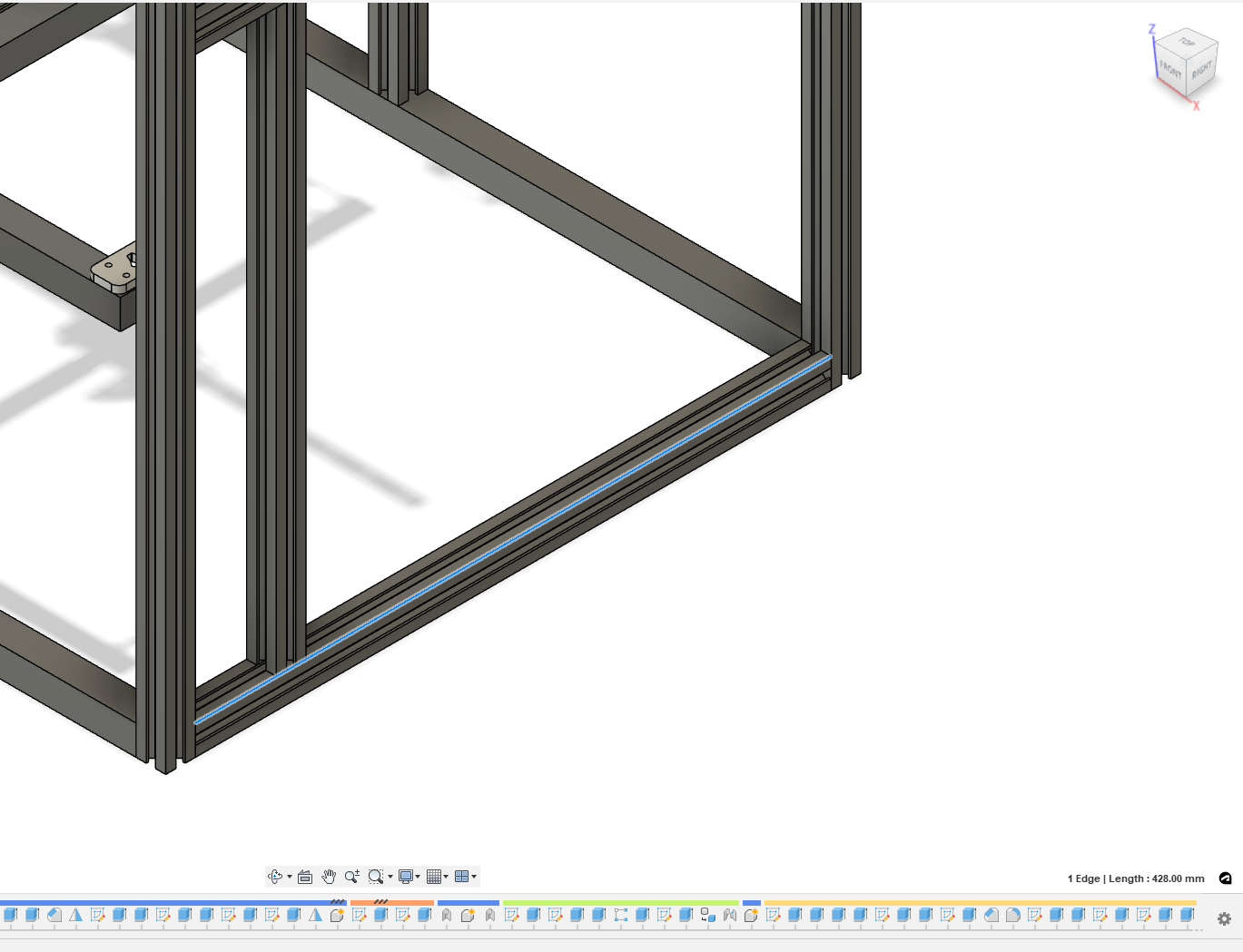
If you want to see how long a part is, click on the edge, it will turn blue. Bottom right corner show the length of that line.
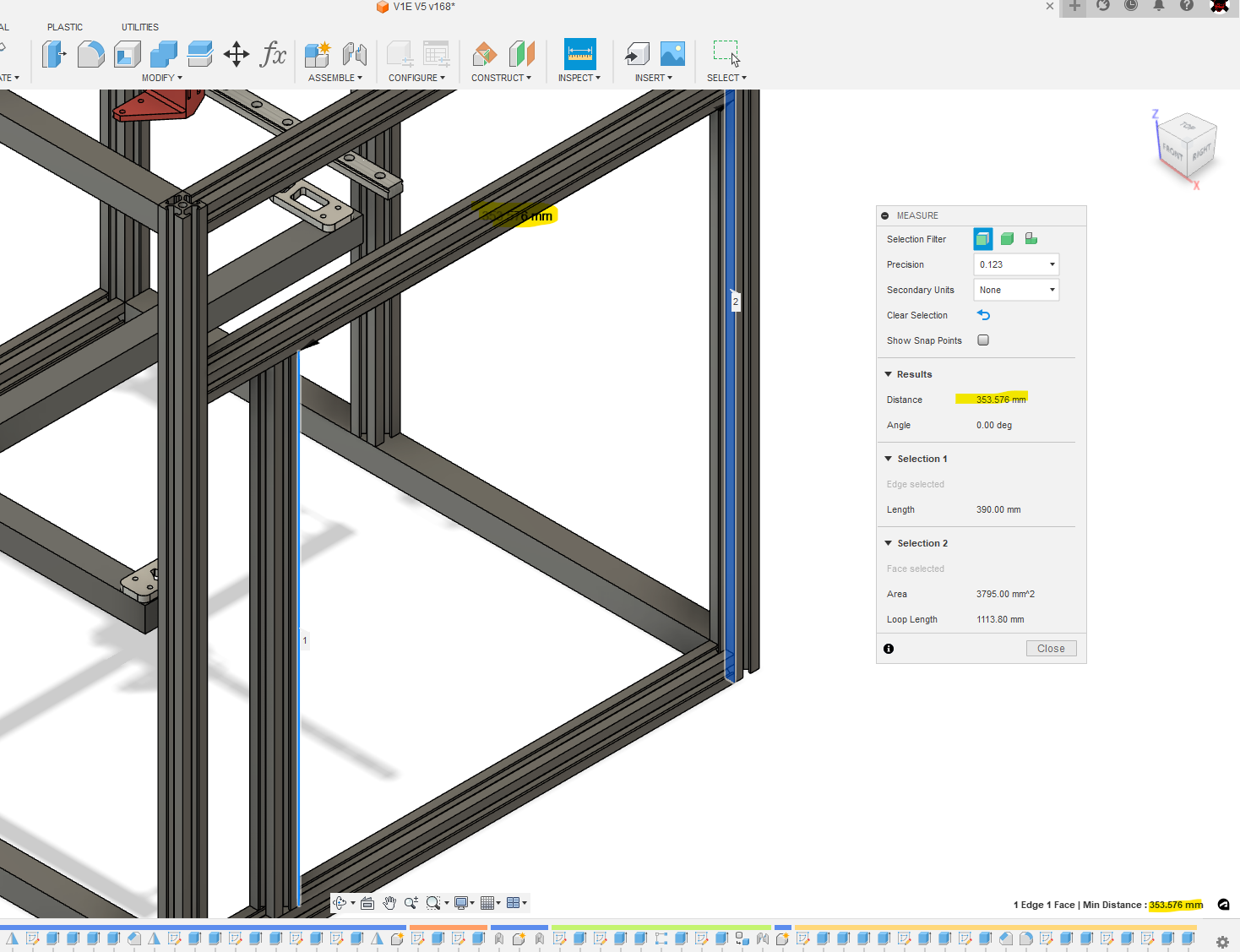
If you want to see how far things are apart hit the “I” key (or the inspect menu, inspect). Click on two objects, objects can be points, lines or surfaces. Fusion 360 loves to hide the actual number so it is listed in several places. This can be tricky, make sure it does not measure some sort of weird diagonal.
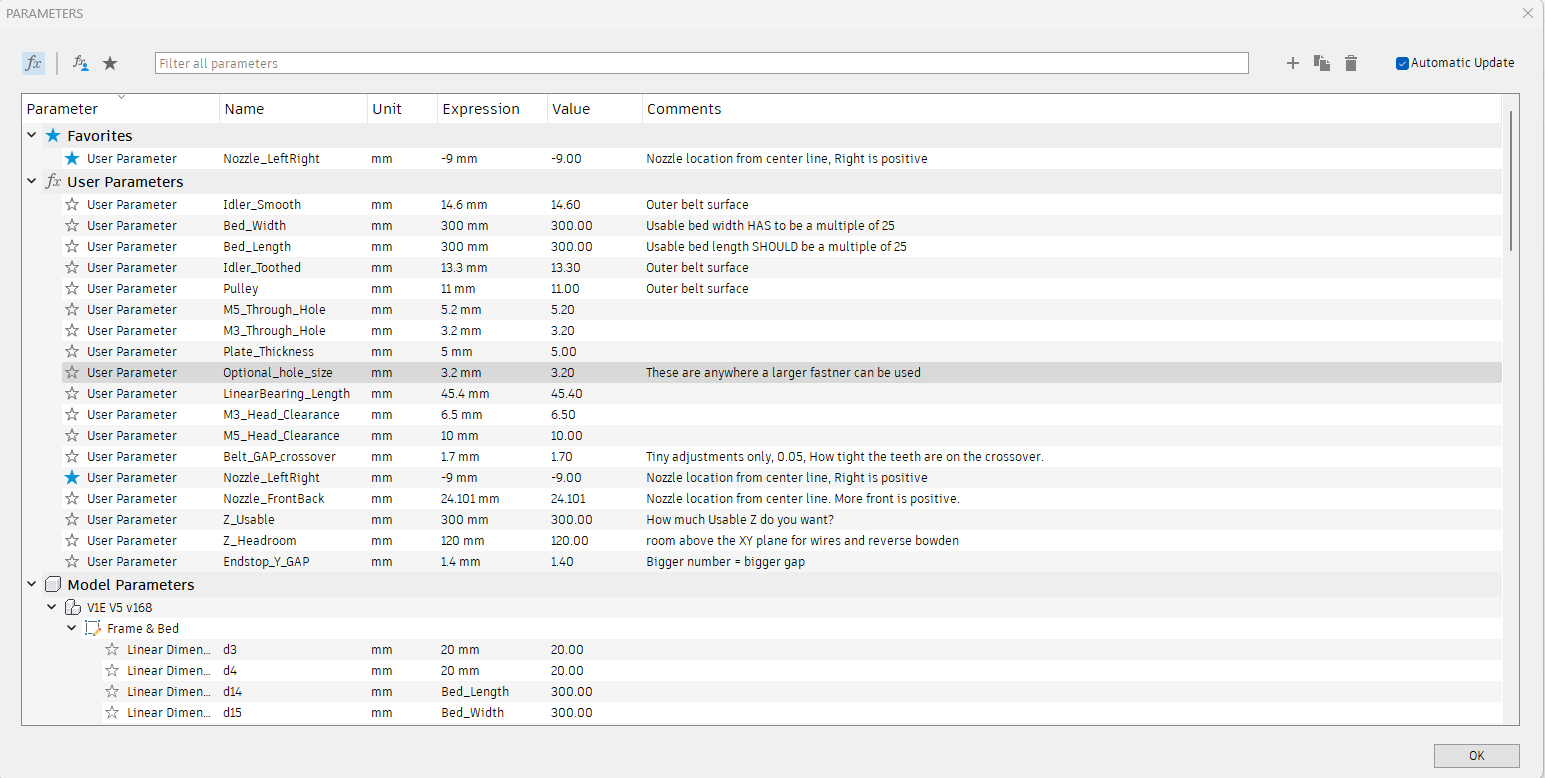
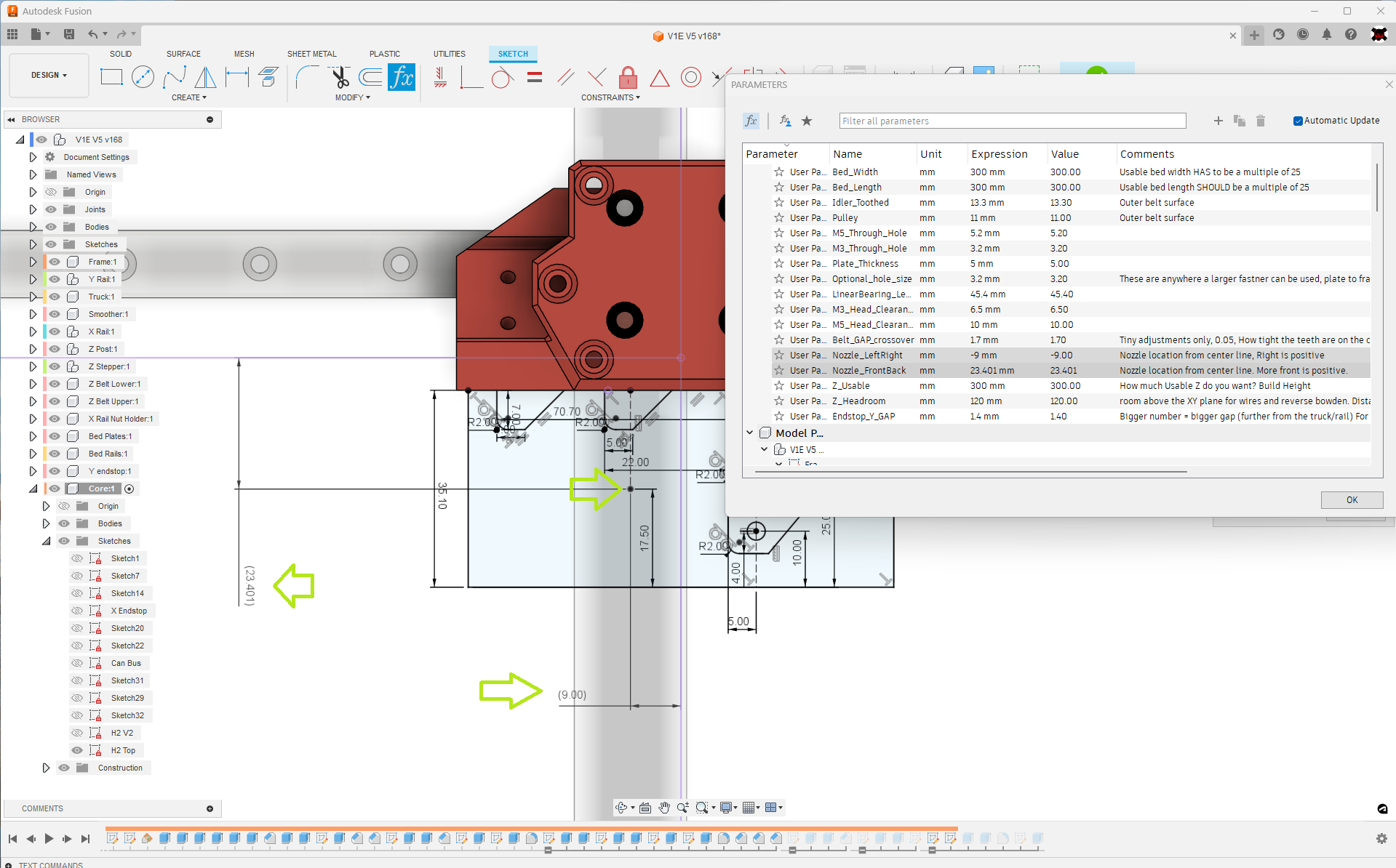
If you choose to make your own extruder mount be sure to adjust these two parameters to your nozzles actual location. This will make sure the bed and Z steppers are located properly.
Note- this is not the nozzle offset used in the firmware. That has to do with the Probe location.