Well I tried my best to come up with a solution that could mount the end-stop to the tool holders.
Either I could:
1.) Side mount it. Problem is a glancing blow to the switch which means I wont have the precision I want due to geometry.
2.) Mount it to the bottom to hit something on the core. Problem is I would always have to grow the tool mount lower meaning longer Z dir, which i disliked because longer moment arm.
I ended up just deciding on what i did before. I could have gone fancy and used a optical or hall sensor, but i think simple mechanical is better. Less chance of outside noise messing it up.
While I find the Prima core design to be beautiful all the flare has made FreeCAD stl to solid conversion a nightmare. Just in a importing the mesh it slowed down my view rotations. 
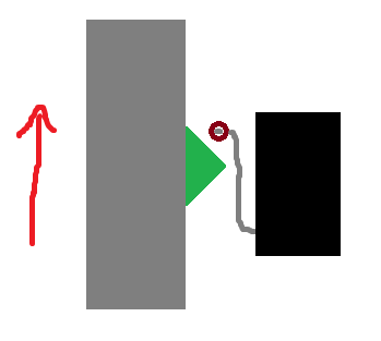
First figure is my plan. I was trying to mount the switch at the top since it hits dead center of the upper tool mount but it was hard to get the cables to thread between the upper bearings where they would be safe. So i was going to drill and tap some holes in the meaty area below. I will probably do the same up above and make a simple wire clip to hold the wire dead center between the bearings. Will probably make another clip that uses the rod mount holes to make sure the wire stays clear of areas it could get pinched.
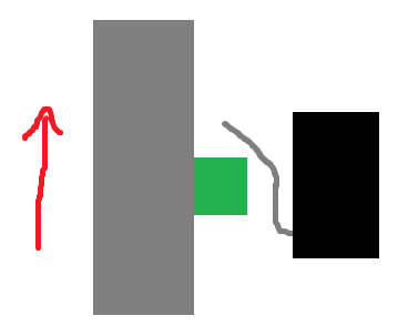
Second figure is my begging…  … Ryan…
If possible a minor change to the core profile would make a flat surface for mounting provisions for a mechanical limit switch and wire clips super easy. I realize you very busy getting other conduits set up. But without the step files i would have to build from scratch (not going to do it) and i would loose the sweet V1 Engineering flare. If this is too much i plan on just drilling and taping into my current print and maybe making some radius blocks and shims.
Backseat designing talk:
It looks like the core is using a solid subtraction that is symmetrical upper to lower. If you add the mount holes to put a limit switch dead on and use symmetry to put it on the upper area as well then its two very simple little parts for limit switch shim and cable holder. These two additional parts and the redesigned tool holder (next figure) would all that is required to add Zmax limits. (Completely optional just like the X&Y limits for dual end stop.)
The third figure is my planned tool mount. I was going to use a slotted hole and screw that way there was adjust-ability. I could just build it into the mount with plastic as well. Could just make the model parametric so users could set the height of the protrusion or screw hole.
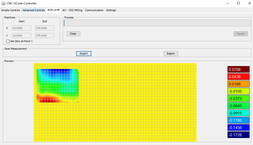
Fourth figure is just a why the heck does this guy want a Zmax:
1.) This is a heat map of my surface of a PCB. When I do a tool switch I keep my bit loose in the tool go to the last bit height in global reference then tighten the collet, the set my offsets there. No needing to retouch off.
2.) Had to stop the program because it was too late. No issue just pause, record % complete in your code and offsets from global and shut it down. The next time I re-home reset my offsets from global delete the g-code i have done and hit go. No need to re-touch of work in any direction.
3.) Need to pump out a lot of something. Jig up your space, cut your blanks the same, write a prep g-code to set offsets off global. Start making chips. Profit.
4.) To mill curved wood things, bats etc… I glue stick some tinfoil over it and use the same PCB heat map methodology. Cant get too crazy due to 2.5D setup, but it works good enough.
Figure 1:
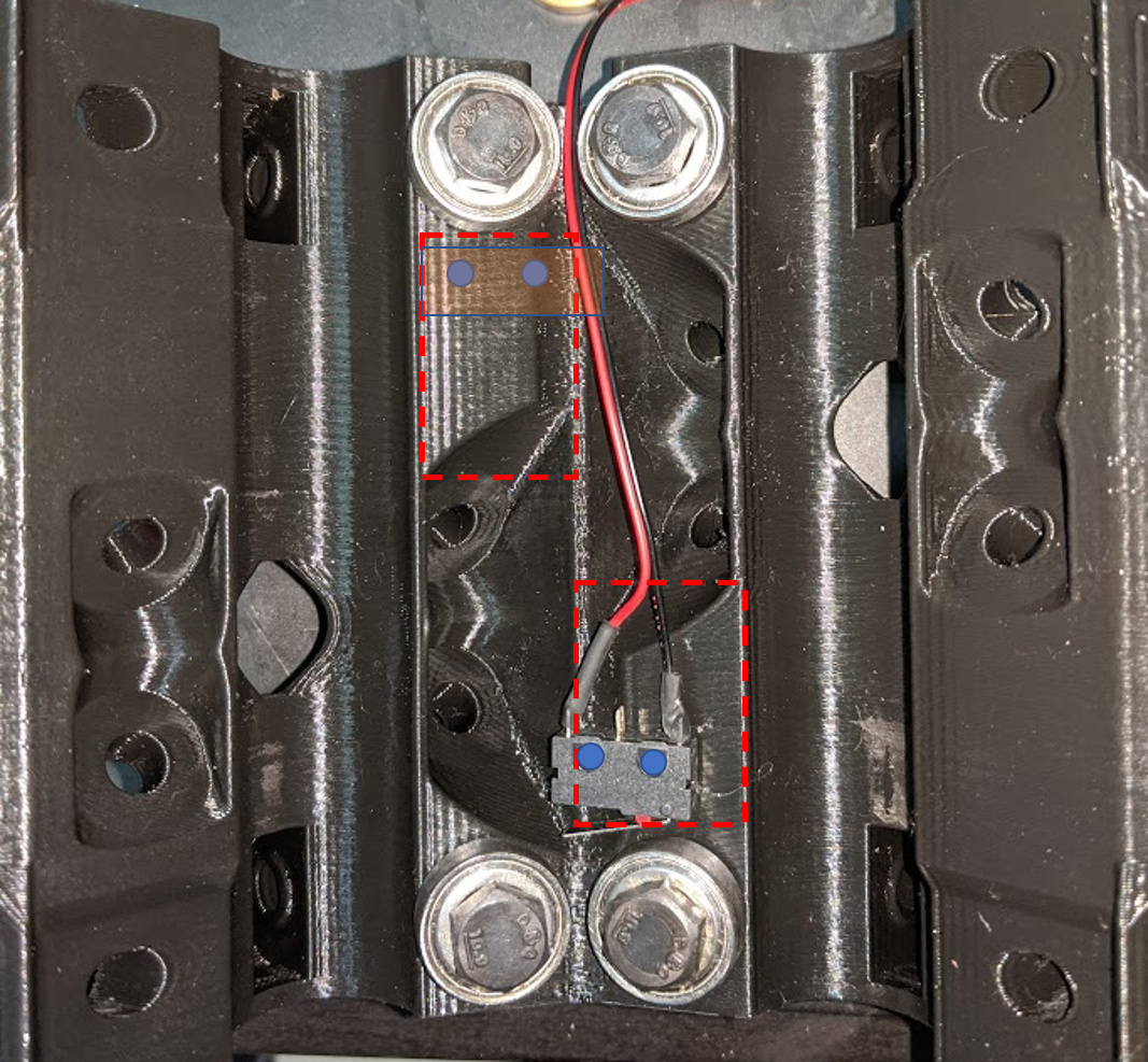
Figure 2:
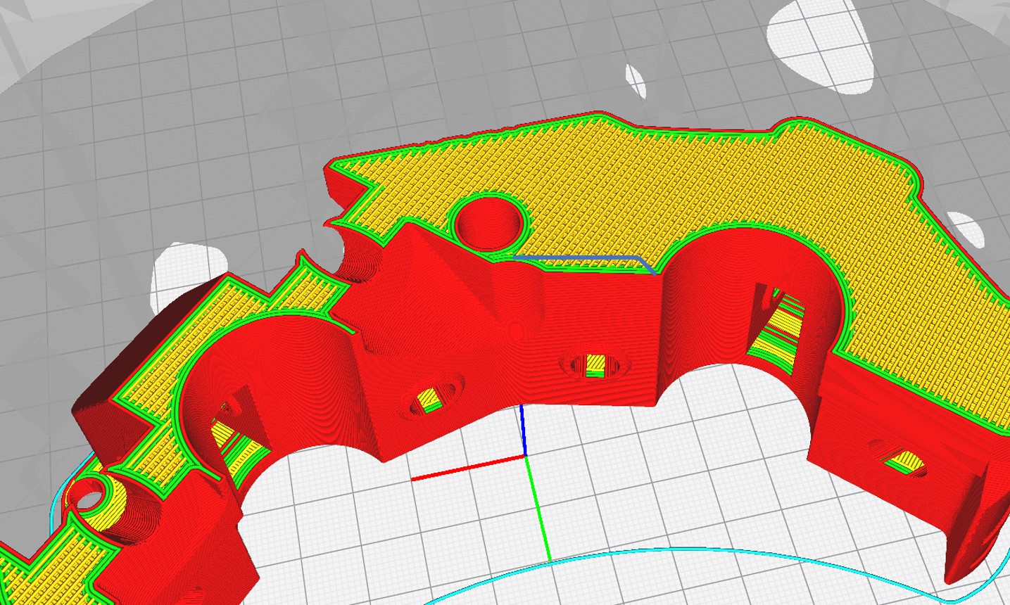
Figure 3:
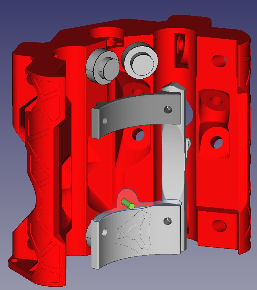
Figure 4:


 Which means I would have to drag it out for setup again if my machine lost power or i let the motors idle… maybe because i hit the panic button.
 Also I need the vacuum because with no vacuum the dust gets way too bad in the box and when i open the door it would snow sawdust everywhere…
