Ok Jeffeb3 gave me a step I must have missed, now it looks right… think it is just a newer version so things a little different
all sorted i was trying to load the program via the file tab up top but it needs to be loaded via the platformIO through projects… all working controlling motors manually… thats a start
thanks again…
1 Like
Are we missing a step or screenshot in the docs?
I do it exactly as the docs show. The key is choosing the right folder, you have to get the folder just above the platformio.ini file. It is not required to do it with the p.io tools.
While setting up a new computer I am double checking all of our instructions.
1 Like
I think the trouble is, you can open a folder, as a regular bunch of files. Or you can open the project in the platformio dialog and it gets tested as a platformio project.
You do have to get the folder with the platform.ini file.
well i got mine all connected and did some test movements… checked that the home works on the x and y axis… and then got the z axis to work on a touch plate… had to change it to the other z axis port… all good… in testing the movements i did notice that the x and y moved as per the display eg 10mm or 1mm… but the z axis would move about 2 mm for the 10mm is this normal or do i need to change a setting some where… this is as far as i got due to other commitments…
Do you have a 1 start leadscrew? It should be a 4 start.
If you have a 1 start, you need to increase the steps/mm by4x, but also drop your max Z speed to about 3-4mm/s, because the motor loses torque at high speeds.
M92 Z1600 ; increase the steps/mm to 1600
M203 Z3 ; reduce the top speed in Z to 3mm/s
M500 ; save these settings for the next restart.
Cheers, i just need to find time to have a play… the whole G-code stuff is a bit of a mystery to me at the moment… I have built this lovely machine and have no idea how to control it yet… I have down loaded Estlcam and Repetier as i believe these are the go to programs but seriously i have no idea from this point forward…
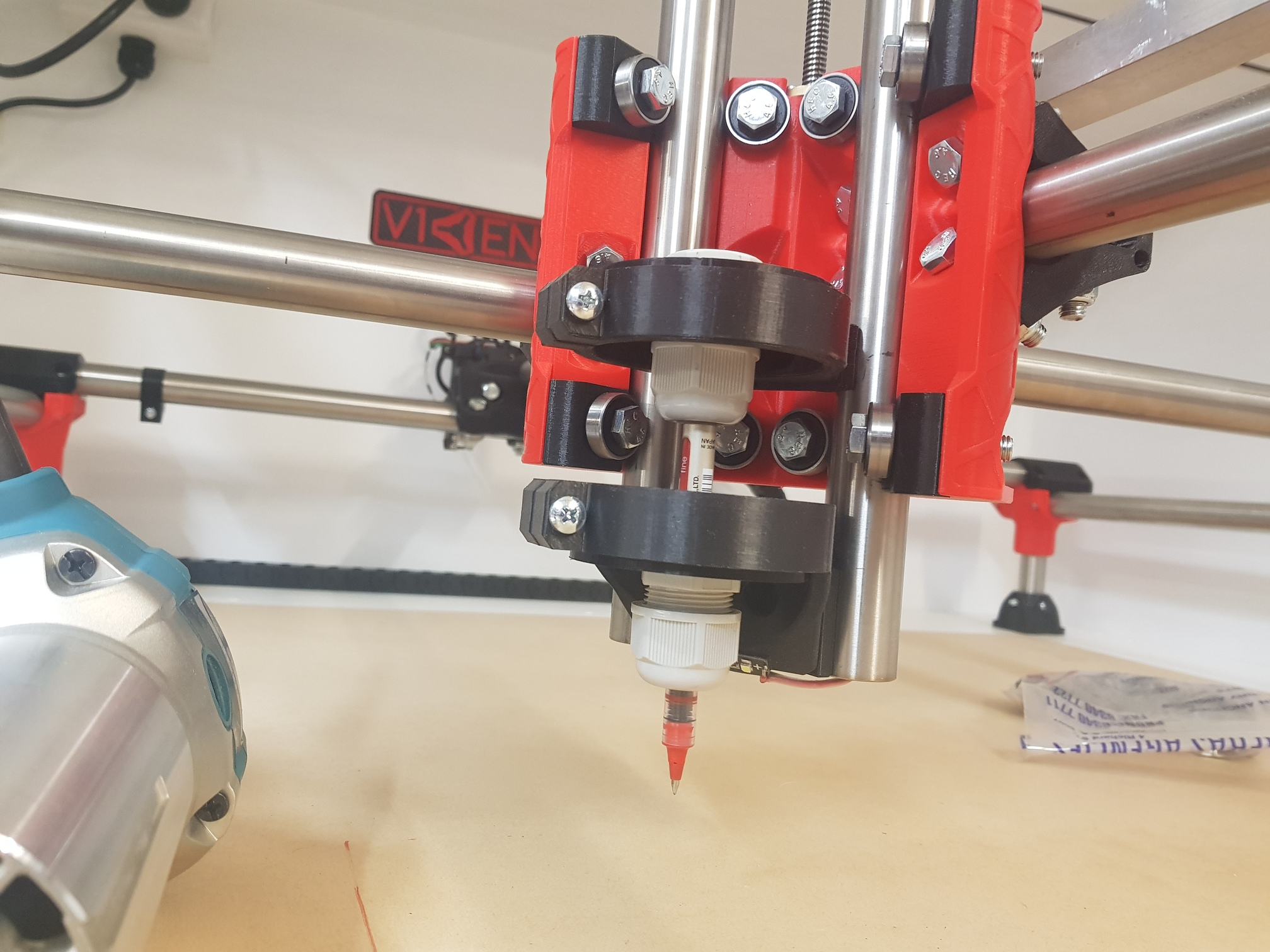
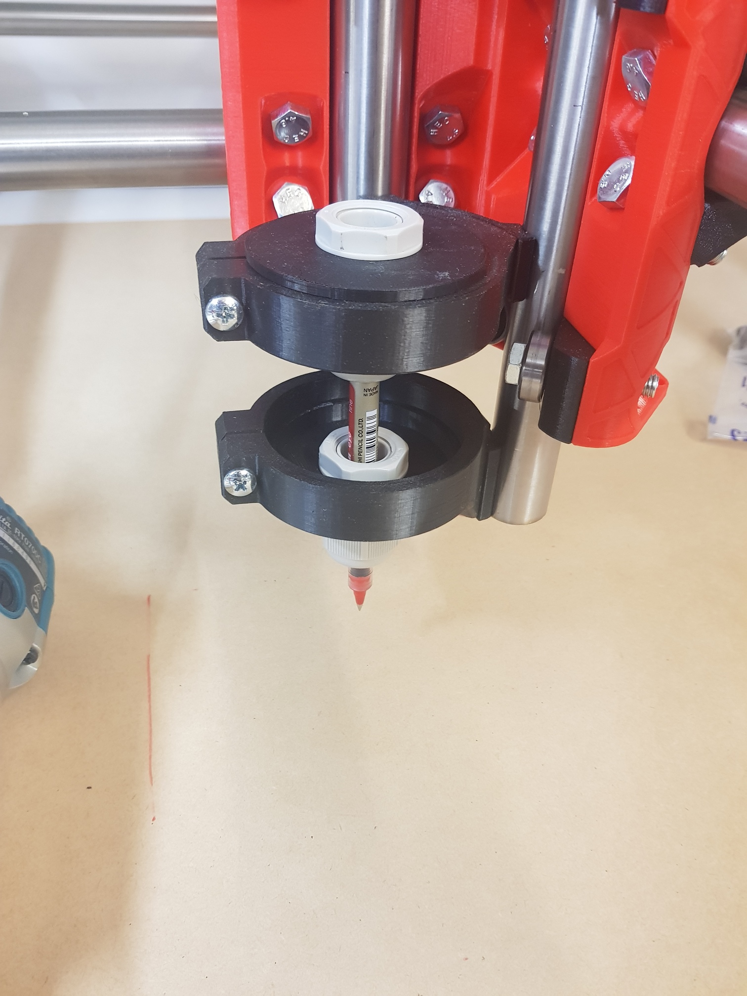
Printed a pen holder last night so I can do some test drawings… came up pretty good, uses 2 20mm cable glands so I can fit various diameter pens
5 Likes
ok so now for the next stupid question, hoping i haven’t missed something in the instructions… so i remember reading about needing to setup the program to suit the CNC… so in repetier host i found these 2 menus as pictured… do i have to edit these to suit my CNC?? secondly i remember something about setting stepper motor maximum currents… is this in the program or in Gcode… still trying to find my feet at the moment…
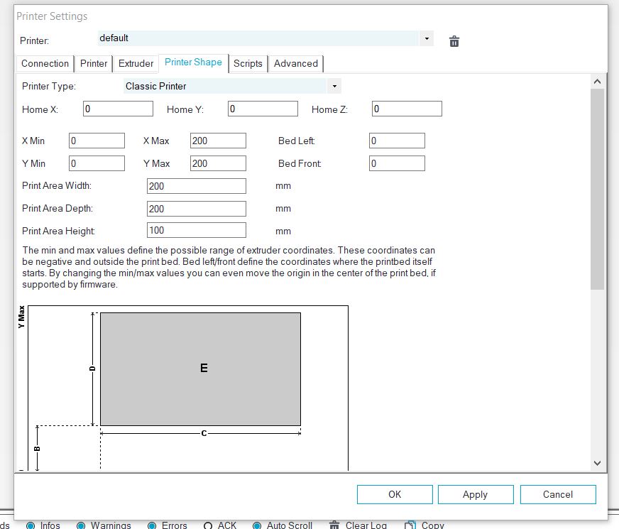
Leave that stuff alone. Repetier host is sure it knows what it’s doing. But it definitely does not.
The settings you should care about in RH is the port, baud rate, uncheck the box that says something like, “Disable motors after the print”, and select “show travel moves”. I honestly haven’t used RH in a few years now, so I’m not sure if these are all still a concern. But the printer size and steps/mm shouldn’t be changed in RH.
Is there are particular problem you are trying to solve?
1 Like
Repetier Host will use the printer shape information if you’re using it’s plating features for adding things to be sliced before 3D printing them. I wouldn’t bother filling that in for the MPCNC milling setup.
No, no problem… just being overly cautious that’s all… making sure I have all the settings correct before I start… I have done all the settings in estlcam and h ave been playing with that… I just need to check for square by drawing the rectangle and adjusting as required… hopefully this Sunday I will get a chance to m a key some dust…
2 Likes
Ok so I got the pen in and did some drawings… rectangle came out 1mm out of square but got that sorted by moving endstop… crown drew really well and only took a few minutes…all good… So I tried to cut a circle but it was going to take 1hour 53m to do a 20mm 4mm deep… something gone wrong with my settings…
secondly… I’m trying to make holes for tee nuts… I drew it in tinker CAD but I couldn’t get estlcam to see it properly and would only see the large diameter part… does it have to be a dxf file??
Thirdly when estlcam plotted it’s cut path it was going side to side, how do u make it go in circles??
Thanks for everyone’s help… slowly getting there…
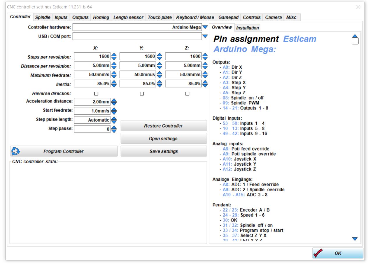
You shouldn’t use that page (the controller page) unless you plan on using the estlcam firmware. The rambo and skr can’t use the estlcam firmware.
Dxf or svg
My first guess is units. That is pretty far off. Have you looked at the estlcam basics page in the docs?
Yeah made sure I had the basics right… 15mm/second for x/y… 3mm/second for z… I will reset all my settings and re do them… I’m a bit puzzled as the crown drew perfectly fine… I will have another play tonight… cheers