As you might now from another topic I researched how to make a boom arm since commercial arms are just too expensive and can’t quite do what I want. I have come quite a way since then and am able to present half a product. Here is the video of cutting all the parts. The next video will be the assembly. Then I am going to have pictures as well.
I am going to upload the drawings here as usual when I have completed it and know it works…
For the sides and top I used this one Sorotec Online-Shop - Werkzeuge and for the 21mm wall mount this Sorotec Online-Shop - Spiralverzahnt neue Serie. I bought the “Spiralverzahnt” to see whether the cuts are any different to the “Diamantverzahnt” (that’s the one most seem to use) but besides being cheaper I didn’t see a difference.
You are right though, the cuts are pretty clean, that’s why I’ve never bothered with a finishing pass so far…
Those are recommended for plywood, because one and two flutes always rip the top layer out. The ones I use are more of a file, they make pretty fine dust.
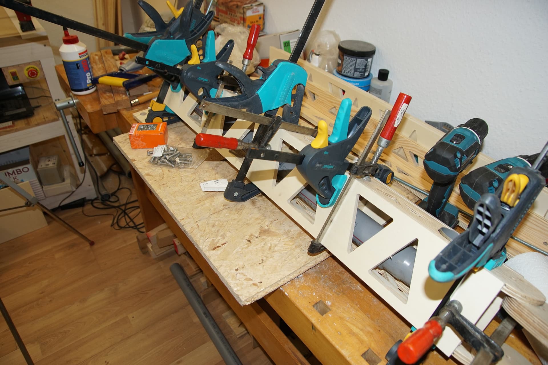
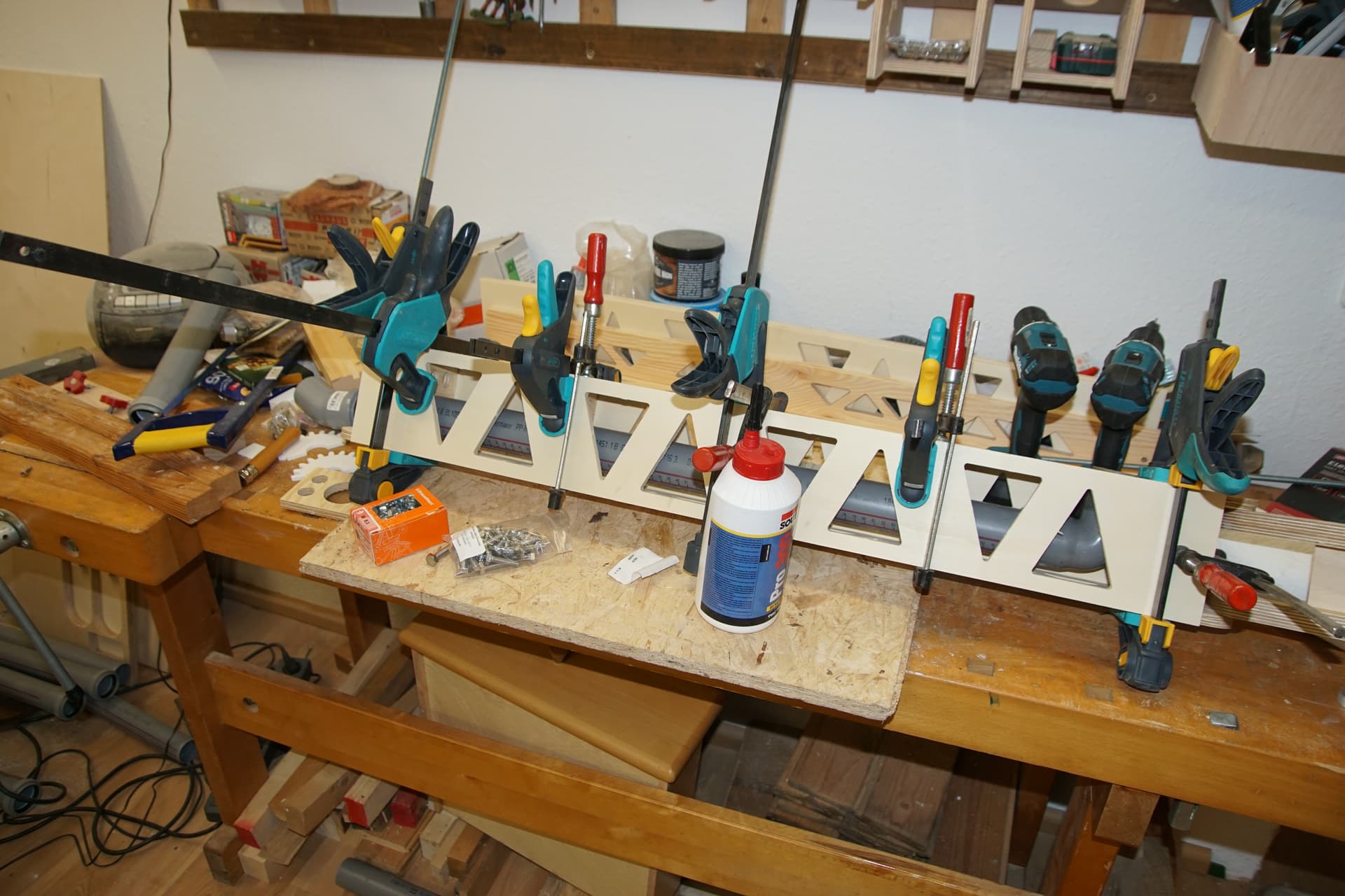
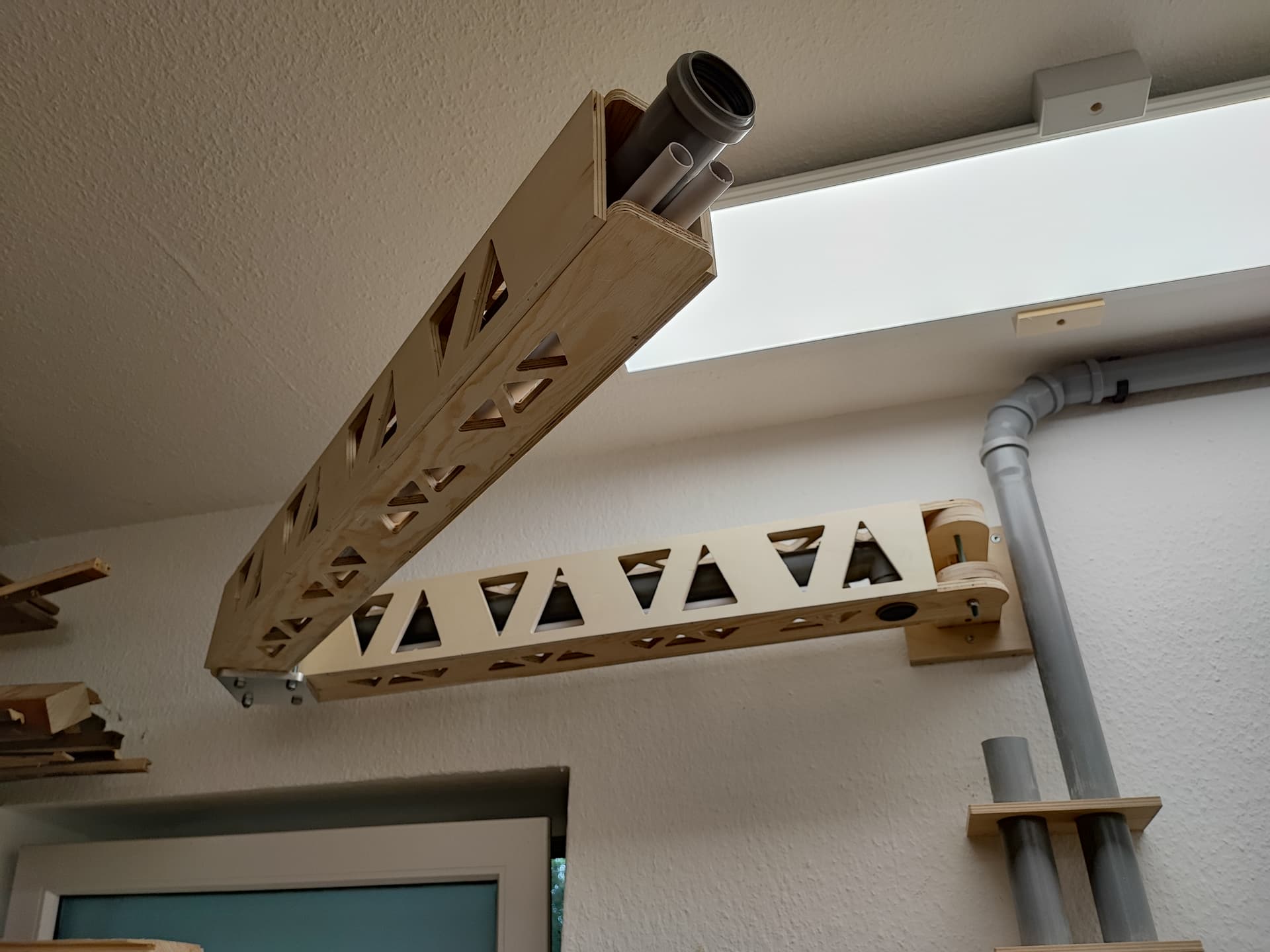
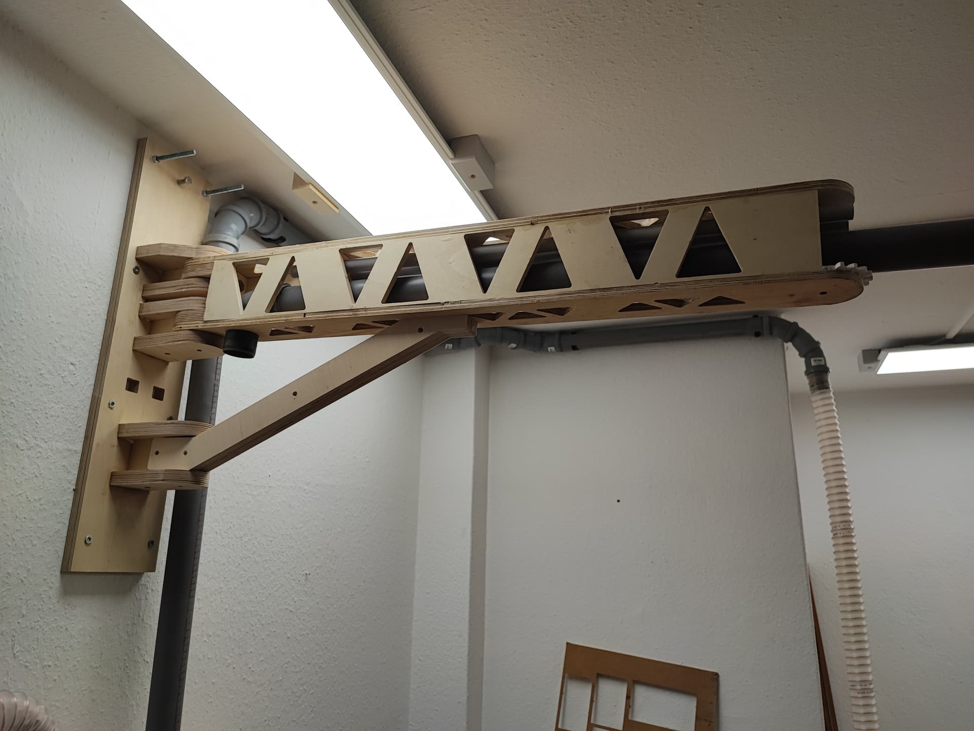
/edit: Looking at the picture I can absolutely say that it is not going to work with the wall mount… look at the top picture, right corner: it’s not going to be able to swivle… ugh. Have to shorten the sides. Good thing I forgot to properly glue it and only did so at the bridges…
Nah, even better. I was also too stupid to apply glue to the top and bottom, just to the bridges, so I can just put it on my circular saw sled and cut off 4cm. Sometimes being dumb helps.
First test fit. The bendy bit in the middle is the bee’s knees and absolutely rocks. I really can’t put that into words.
The wall mount sucks donkey balls though. It is much too small, the arm wobbles and the first screw is already loose (I hate that wall…). I completely redesigned the wall mount, made it much bigger, included bearings etcpp. So a complete overhaul. Might be a while until I can cut it though.
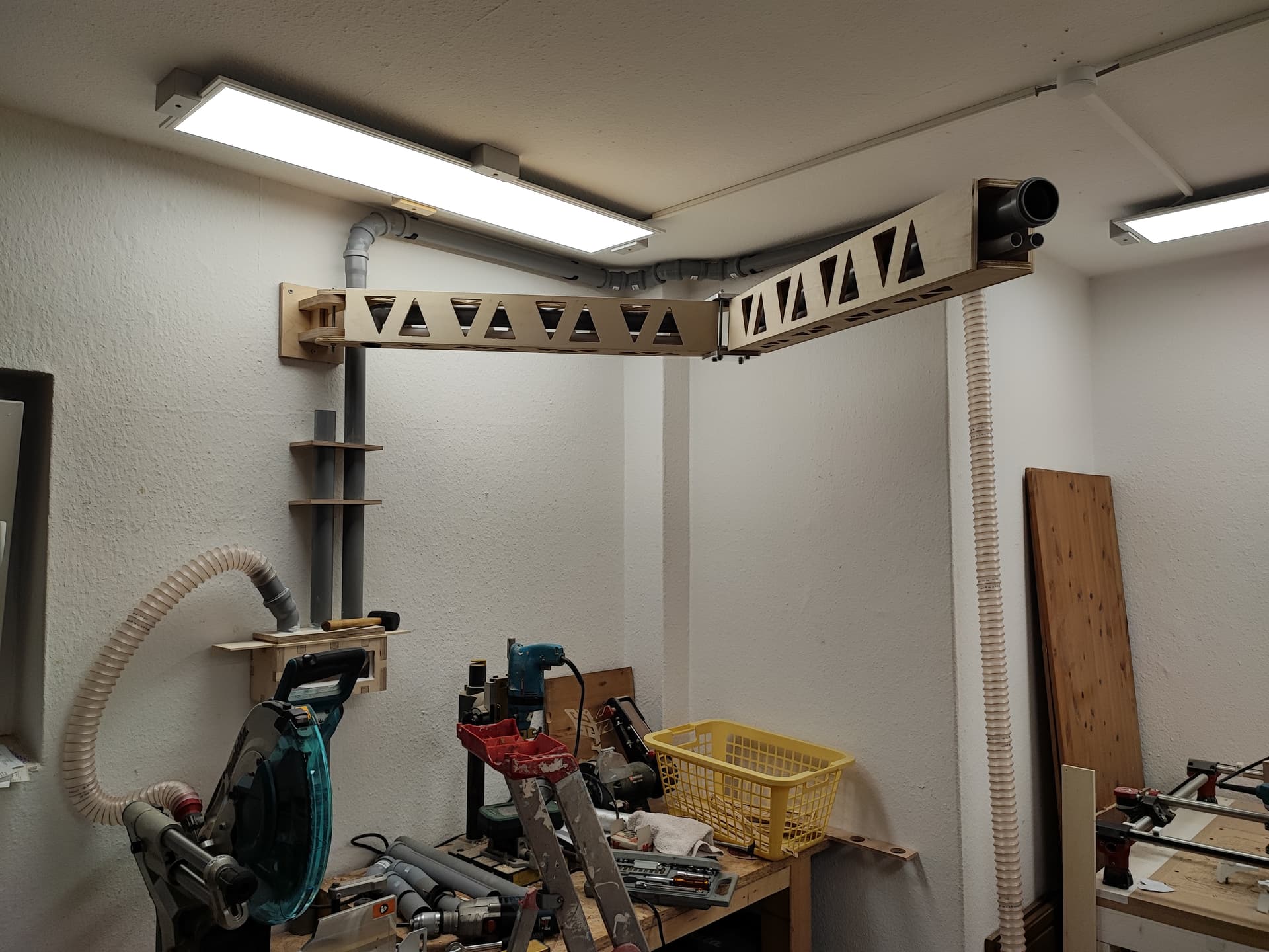
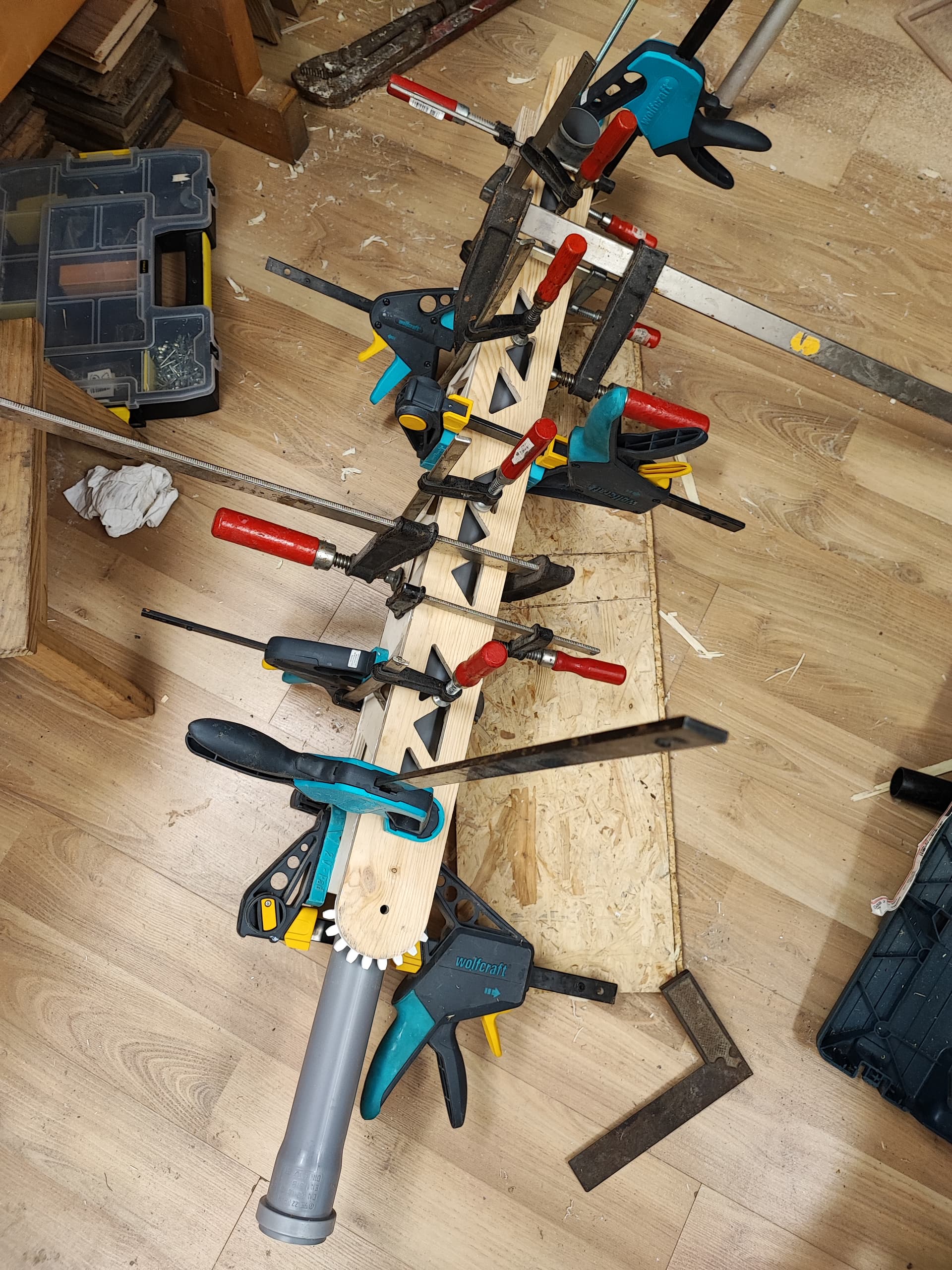
I took it apart completely again and changed quite a bit… The sides are not on the outside any more, but moved to the “inside”. Maybe you can see it in the picture. I think this will give a lot more stability because the top and bottom cannot crack or bend without taking the sides with it, which they could have done before. The arm should now also be able to bend nearly fully, because the sides don’t block it any more since I forgot to calculate them when cutting the hinge in the middle. Also, the pipe is now at the bottom and actually sticks out so I can actually connect the hose without an adapter.
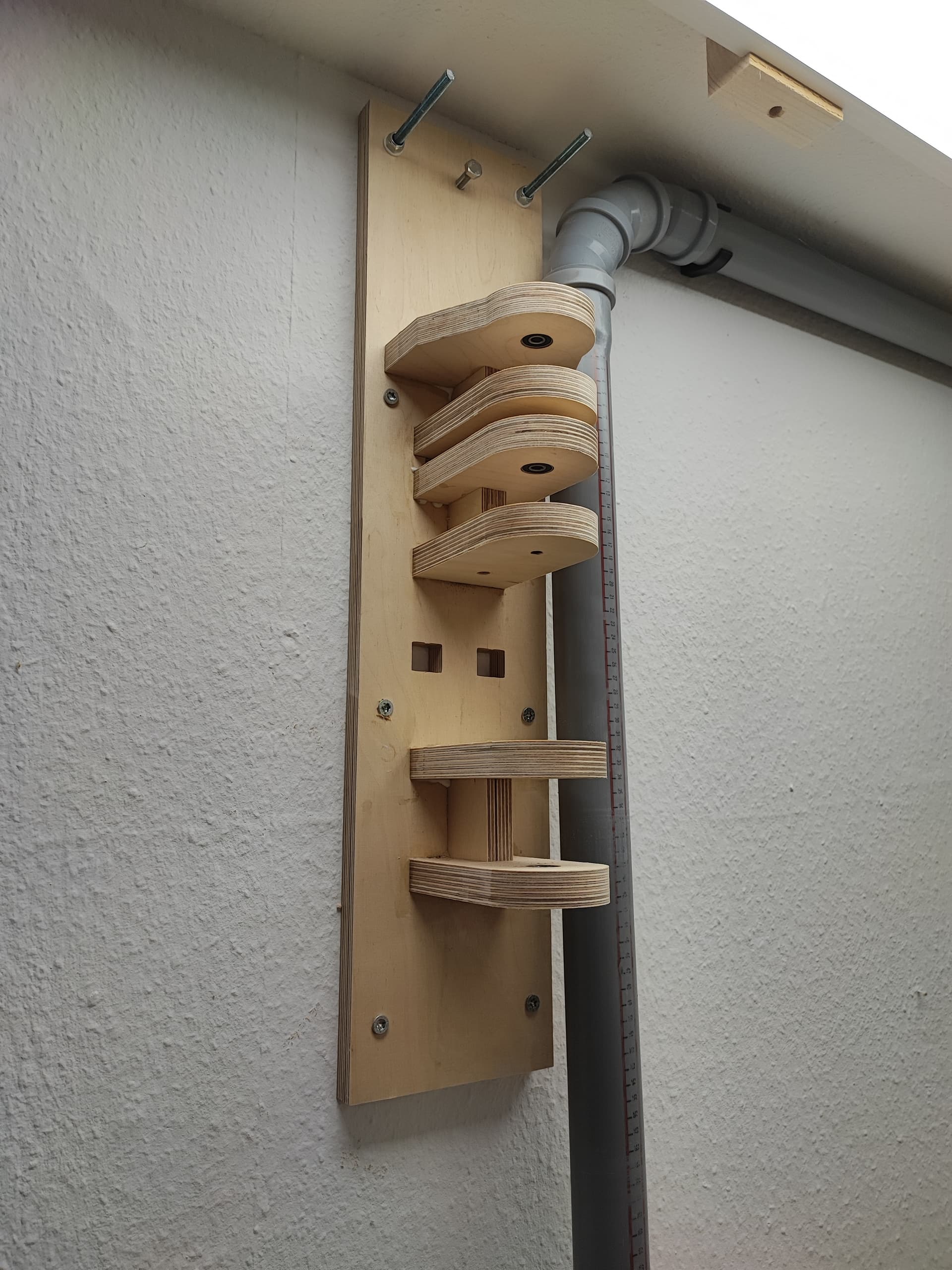
Sine my wall is 27cm sandstone (used to be a garage, they seem to have added this later) and then 8cm brick I drilled through the whole wall and fastened the top with 8mm rods. This thing is only coming down if the whole wall comes down now.
Ignore the two empty holes… I miscalculated and had two make two new holes with hand tools, like a caveman… In the plans I uploaded I fixed the error.
The arm fits (not fastened, just easily chilling there), there is now also a support beam (don`t think I’d really need it, but better save than sorry).
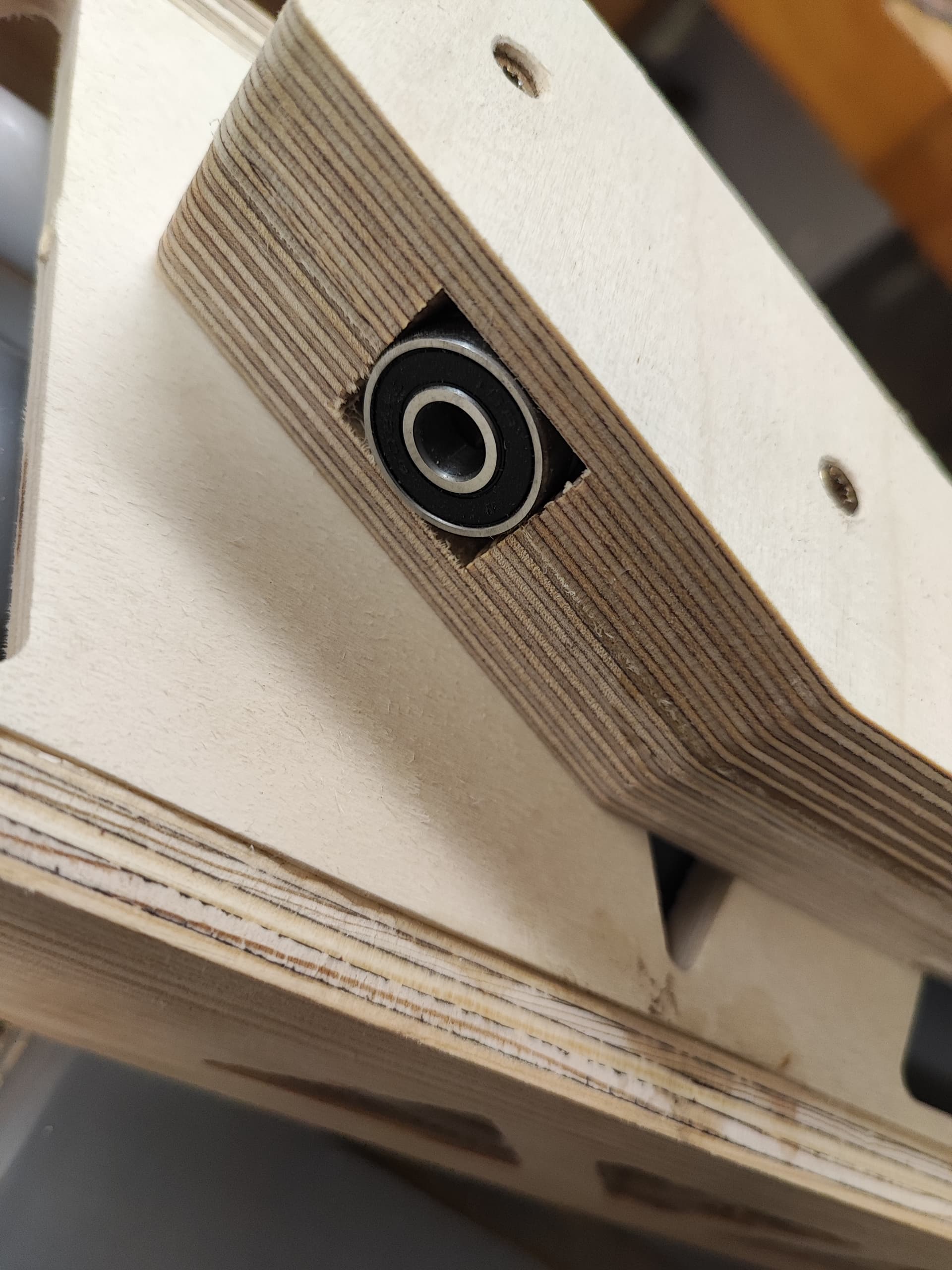
Two parts, glued together, including space for bearings (as all the other parts).
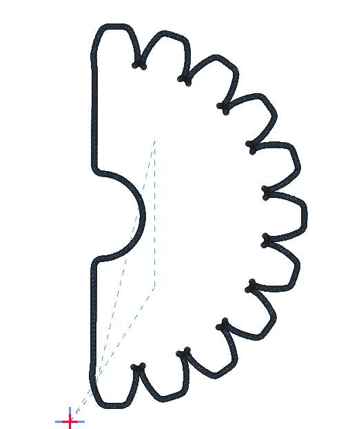
And finally, the dxf. I am really happy with how it turned out. There are annotations, but you can’t see them in Estlcam. Use LibreCAD or AutoCAD to read those.
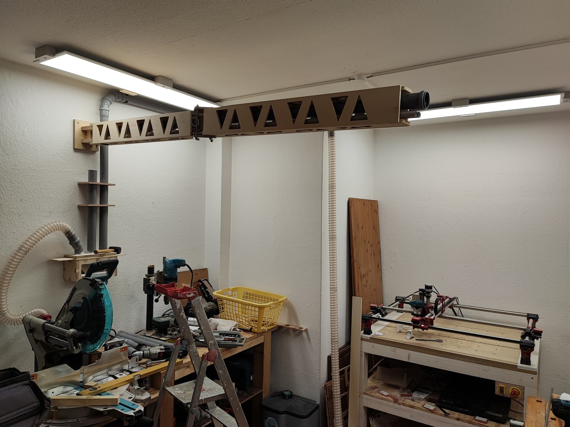
Looking good! When I first saw the second photo I thought to myself why did he make such a large arm for that tiny hose. Optical illusion from the hose on the back wall.
 Part I - Cutting the parts on the MPCNC")


 Part II - Putting the arm together")
 Part III - Remaking the Wall Mount")
