@vicious1 I’ll take all the pictures you want… I’m fairly confident that it’s correctly assembled. I am running it fairly fast, but found that it seems better behaved when it runs fast. It slows down a lot for curves, which is when it shows the biggest problems.
I 3D printed a shim for the magnets, which is further shimmed to just below dragging on the hardboard.
I’ve also been thinking the Y rails need to be fully captured. I’ve checked again for parallel on the Y rails and they are as close as I can reasonably measure.
My thought is to add a printed piece outside the bearings on the Y runners to hold one more bearing underneath, and use a zip tie to tension it under the rail. Sadly, this will increase the depth of the mechanism by that bearing’s diameter, but will fully capture the Y rails. I have some smaller bearings that I might use for my own use, but probably could not recommend for others in the “anyone can source these parts” philosophy
That looks fine. I am not sure how that piece can even wiggle so much without something obviously wrong.
Shoot.
While testing for the new build I have sources some tiny wheels. I like them so far. I am trying to make sure it will fit in anyone’s current build and actually use less space but that is proving to be the trick part while fully capturing the rails. That is why I am really interested in how that center is having an issue as I do not want to duplicate it if it is the problem.
Best I can say is watch the zen move (lay under the table if you can). See what is happening when it grinds. Maybe the pulley is slipping and that is making it crooked every so often?
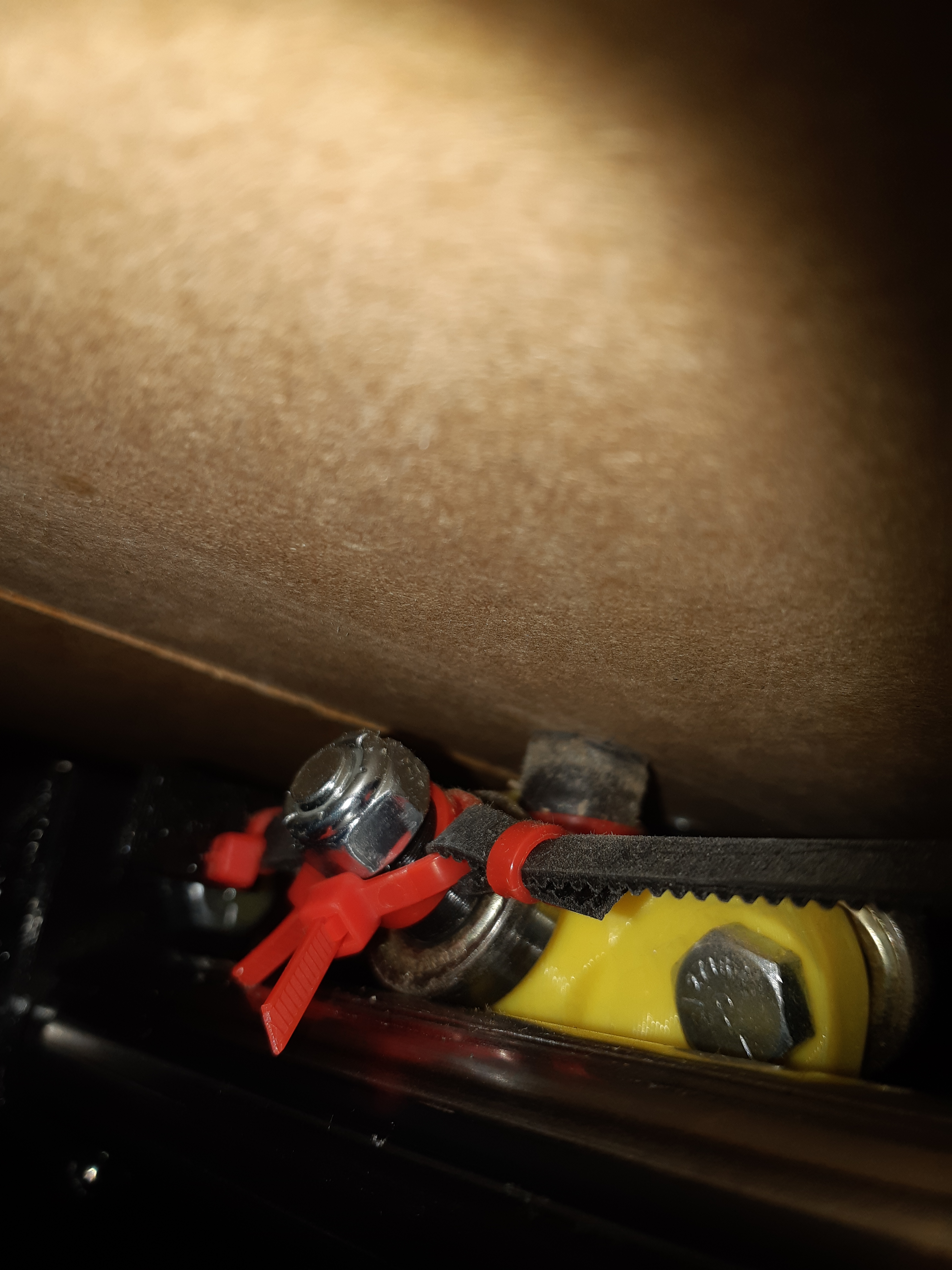
I should point out that I’ve replaced the center print. The one that was moving htat much has been replaced by the bright yellow thing. It was tight when it went in. Lots of juddering while the motor was skipping steps, I think that basically jackhammered the threads into the plastic, allowing the bearings to move more and more. Now it’s started clicking again. This print is PLA (Previous was PETg) the bright yellow is because that’s the only PLA I had left.
The pulleys aren’t slipping on the motors, but when it has homing problems, it can pull the X rails askew. The belt will slip on the clamp at the center as it tries to pull the carriage further in the X direction than it physically can. I have many cut zip ties from fixing this… I’m looking at using a screw assembly to secure the clamp. It has also sometimes pulled a twist into the X rails, which I have to loosen the clamp screws in order to fix. (I could probably gorilla it back into alignment, but that’s never my preferred method.)
I can’t see anything obvious when it grinds. Something is pulling unevenly is the best that I can determine. The belts do not seem to feel excessively tight at the back end, but I can hear them catching somewhere. My intuition is saying that it might be under the bearings along the Y rail… Which brings me to a suggestion:
Perhaps the belt run that goes from motor to corner pulley can be moved to go through the tube. I think that it sometimes catches where the twist is tightest. This happens at both ends of Y travel. If instead the belt were run through the tubes, this twist would never need flatten at the point where it runs underneath the spacers on the trucks, and so could be left to always run the full distance between the motor and the corner pulley. The biggest trick would be ensuring that it only run a 1/4 twist along the length, which would take some careful planning when laying it out, but once done, it would be aesthetically and functionally simpler. It would also allow you to pull the rails a few mm closer to the table.
Yeah… It’s zip tied, but with enough force, it still slips. I can’t imagine what it is that puts that kind of force on the belt, but it happens from time to time. Might be when it’s trying to go past the physical limits of the machine.
This is the reason why I have a bunch of clipped zip ties in a pile because it would go and pull the X rails out of square, and the only way I can (reasonably) put it back to square is to clip the zip tie, re-square it and put a new zip tie on.
Again, I could probably gorilla it back into place, but zip ties are cheaper than new belt.
Something else seems wrong. I drive mine with like 100mA on each motor and there’s no way it is jumping teeth on that connection. I wonder if we had the root problem earlier and we just increased the current and now it is just hurting itself when it binds.
Once again, MOAR POWAA did not seem to be the actual correct solution. I’d like to turn the current down again, but not until I get it to stop binding.
The motors that burned out did seem to be POS quality, but the new ones are as good as any I buy.
I’m going to try fully capturing the Y rails, to see if that keeps forces aligned the way they need to be. Something went wrong somewhere, I fully agree.
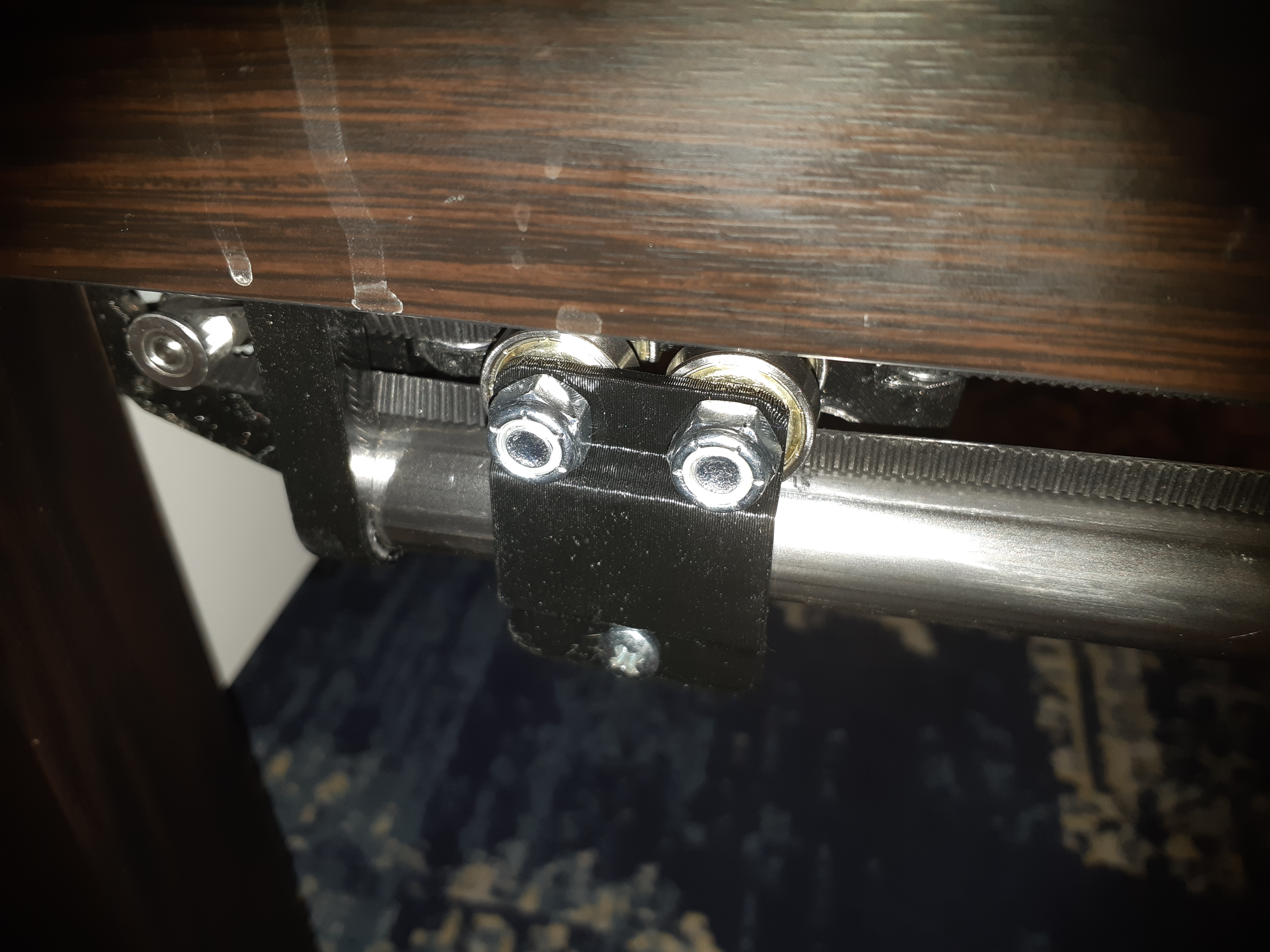
So this is my temporary fix. The thickness is based on the amount of thread still showing on the 5/16" bolts that the rail fits on. I am using leftover 5mm X 30mm screws and some 5X10X4mm bearings that I have around. The project they were meant for went another direction, and I never ended up using them. I printed a 10mm spacer for the bearing. It fits reasonably over the 1" tube and holds the truck from lifting. I can still flex it enough to lift the 608 bearings a little, but nowhere near what they did easily before. I think I can zip tie the end of the bolts to keep the bearings under a little tension, but I’ll try without first. I don’t want to introduce more problems.
Edit: I don’t know if I introduced new problems, but some of the old ones are back with a vengeance. Without the bearing on the bottom, the trucks would sometimes wobble a little, which bugged me, but it didn’t seem to matter much to the ball position. It would be fractions of a millimeter, not a big deal. Well, turns out that what it was doing, with accompanying noise was catching belt teeth with the edge of a bearing. Now that it can’t jump or move, it catches and grinds. This probably means that something isn’t centered on the belt path somewhere. I may have to take the whole thing apart and re center everything. Maybe I’ll move the 0,0 point a quarter inch in both dimensions to keep it to where the ball can actually go. This may require a new table top, which is a shame, but I can make it work.
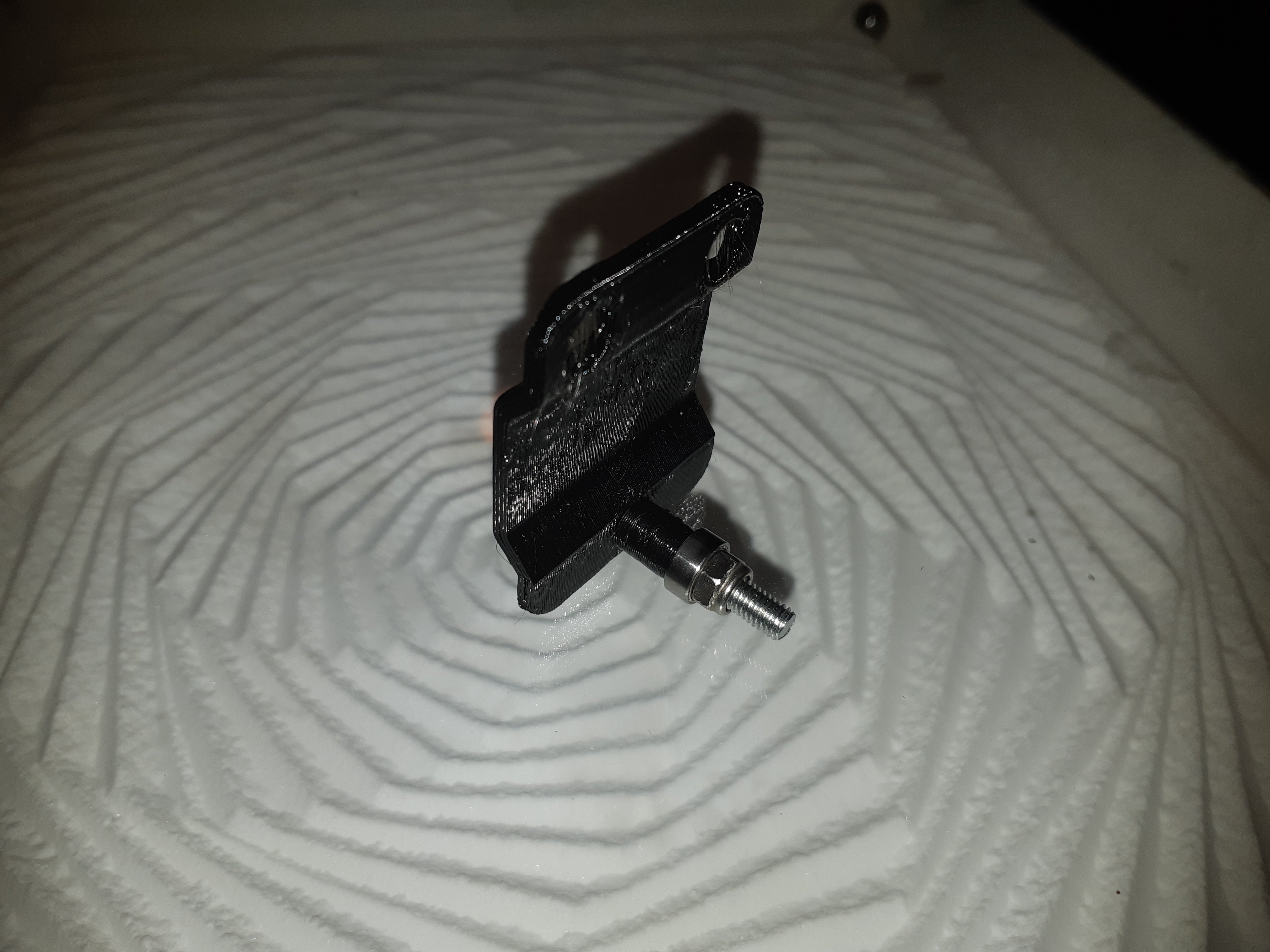
y capture.zip (14.0 KB)
Anyway, FWIW, here is the STL of the Y capture print that I made. It was designed in FreeCAD. It has 2 8mm holes spaced 25mm apart with room for the nuts, and one 5mm hole for the retainer bearing. If people want, I’ll share the FreeCAD file, but it’s likely to be seen as kludgy, since I’m a total beginner when it comes to this as a tool. At least changing the distance between the bearings is easy enough with the CAD file, which was all I was concerned with initially.
(Aw heck with it. Here’s the FreeCAD file, too.) ZenXY Y Capture.zip (94.2 KB)
I won’t bother with the spacer. It’s a tube, 8mm OD, 5.2mm ID, 10mm length. I’m pretty sure that anyone can manage that without my help.
Tweaking and centering everything. Still not perfect, and it still clacks and grinds. Maybe I should replace my printed wheel spacers with metal, or reduce the printed OD a little. That may reduce the belt catching under the axles, which appears to be the main problem. I think there is a slight bend in one of the Y tubes as well, maybe a millimeter or so run out along the length of the axis. It seems to me that was the reason not to use that part in the MPCNC. Both 20’ lengths of tube I bought had a section like that.
The belt seems to catch and snag on the printed spacers between the bearings riding on the Y axis.
There is a slight bend in one of the rails, it bends inwards, it’s barely findable, it’s less than 0.5mm narrower about 3/4 of the way along the Y rail. I’ve rotated the bar so that the direction is downwards instead, but it doesn’t seem to make a difference. It’s close to Minimum and maximum Y that the belt snags on either the spacer or the bearings. I’ve re-checked that the motor pulleys are as close as possible to the centers of the openings (therefore the center of the rails) so that shouldn’t be the issue.
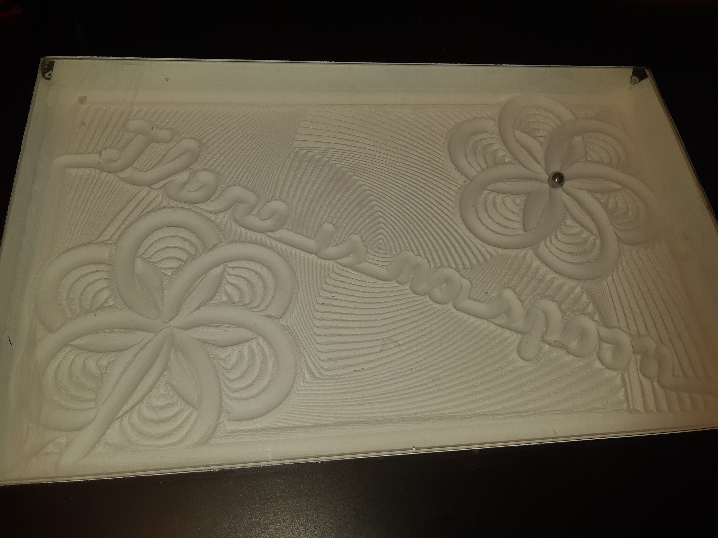
I’ve been playing with Sandify a bit. I’m trying to make it a performance, rather than static art. That picture is after a run that re-writes the picture several times, with different text at different times. “Don’t Panic” (Or rather “Dont Panic” since the apostrophe doesn’t print) “Relax I got this.” and “Time is an illusion” appear at various points in the process.
I’ve manually edited the Gcode at points, where there are a lot of straight lines, I find that it works well to speed up the process, but where there are mostly curves, it seems to be all that the controller can do to keep up to the commands. I’m starting to think that I might want to see what a Duet can do with it after all. My spare is out for repairs, probably the new year before I get it back.
Someone mentioned using this as a clock. I’m working on a New Year countdown pattern. It will pretty much have to be run from a python script on the Pi in order to get the timing right, but maybe if I can time certain sequences, I can manage it in Sandify. There should be enough time before the end of December.
That is a fun challenge. It’s a little bit funny because you have to watch the machine draw to really understand it. I tried to do the same thing with my tasting flight pattern. It draws these slow, deliberate shape patterns and then quickly zips out a message of “cheers”. The only trouble was, it ended up being like 7 hours of pattern the first way I made it
Connecting patterns is a bit tricky. Bob and I were working on a branch that allowed some more discrete control, but they were rough features that aren’t ready for the main website yet.
I wouldn’t mind allowing some arc commands. I saw an octoprint plugin the other day that replaced line segments with arcs. You might try that (arc welder, IIRC). I would love to have a feature like that, or at least keep the arcs I draw as arcs.
A big part of the bottleneck is the gcode getting to Marlin. If you are using octoprint, then you need a good USB cable and get the baud rate as high as possible. If you are using the old school LCD, and SD card, then that is a few times faster.
Have you looked at sanypi? I still think there’s a lot of potential in a controller like that. We need more eyes on it and we can really grow its capabilities. It should be able to handle interrupting a pattern at a certain time, or starting a pattern at another time, at least.
I do like hacking around with the Pi. I got my start with stuff like that in the middle 80s, hacking a Commodore 64 to do simple home automation stuff. A photovoltaic, geared 12V motor and limit switches to open curtains when the sun came out, and close them when it got dark. Relays for some light switches when the basement door was opened, a simple timer for shutting them off (Or handing them back to their real switches.)
I think that the Commodore 64 and the user port board that I used to do all that is still in the garage.
Anyway…
I cut a piece of stock so that it exactly fits between the Y rails With the X rails homed, I can run it down the length of the rails now and they never lose contact with the steel. I know there’s that little bend in the one tube, but I can’t see it. this does mean that there’s that little high spot for the magnet, I can hear the heat shrink tube that I put around the magnet brush the table bottom in one spot. (I thought that I rotated the bend down, must have been up.) It doesn’t cause a problem and I can only hear it when I’m specifically listening for it.
I think I’m going to try thinner spacer prints. These are 1.6mm thick (11.3mm OD, 8.1mm ID) to make them 4 lines thick. I think I’m going to cut them down to 9.7mm ODto see if that helps. 2 layers ought to provide adequate strength for a 10mm spacer that shouldn’t be dealing with too much compression.
I really think that raising the tube up so that the lower run goes through the tube would help in a few ways. It would eliminate any friction or possibility of catching in the rollers, it would also allow you to use your trademark 120 degree angles to capture the rails, since the belt itself would no longer need go anywhere near the bearings. It would also reduce the exposed space below the table, it should leave barely any protrusion thicker than the NEMA17 motors if the top surface of the tube is level with the motor center. Doubly true for a 23.5mm version.
It also then brings the belt pulleys for the X axis closer to the rail, less torque on the trucks, therefore less twisting force at the carriage. I don’t think that this amount is excessive if everything else is right, but when something is wrong, it will be more forgiving. (Obviously my build is an example of “something is wrong.”)
For all the problems that I had, I think that center section is brilliant.
Not trying to argue for this. But if you had this, and the other end was just riding with one bearing on a tube to keep it at the right height, it would be pretty tolerant to variances on the other end.
How the heck did you work that out? I still get mixed up with the regular corexy. I will have to make a mock up or something to see if I can make that smaller than the standard.
My issue is trying to make the new one take the same area or less, yet still have fully captured rails and possibly 10mm belt. Just in case the new one is better I would want to make sure it fits any tables that are already built.