Nope…it really is that simple! The only question mark I might raise is that the input power is rated at 12 - 24V and the laser will not like anything over 12V and as they don’t show the bottom of the board I would just check that there is a regulator there to drop the 24v to 12v if you intend to use 24v…better still…just use a regulated brick PSU of 12V @~3A.
Most of that software linked is somewhere between poor to useless. You may need the CH340 driver if you haven’t used a clone nano before on your computer, for the rest I would give it a miss. I recommend you look at LaserGRBL or LightBurn for software.
You don’t need the ‘offline’ board as those functions are also provided by the software.
Also…do yourself a favour and follow their example of buying a laser module with an integral controller board like these, not one of the lasers that have a separate ‘brick’ psu/controller…like these
for the input power: 12V-24V in the description.
For the laser power output, we can read; LSR / TTL 12V GND PWM.
i dont know about the amperage i can ask the seller.
Why not a separate controller?
I have a neje laser master 2, I believe that the controller is separated, I can reuse it with the card that I showed you?
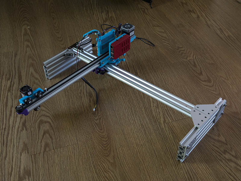
I would like to make myself a laser engraver with a larger working area, perhaps by reusing part of my current engraver.
the card works with LaserGRBL told me the seller.
Firmware: GRBL (1.1)
Input power: 12V-24V
X / Y axis: 1 * X axis, 2 * Y axis, dual Y axis support 2 stepper motor
Support laser: 500mw-15000mw (Almost support all kinds of laser in marsket, you can connect us to confirm)
Software: LaserGRBL, Laser engraver, GRBL
System: Win7 and above, XP, MAC
Servo: support write function
Offline: Support offline work (no need to connect to PC)
OK… forget what I said as I obviously confused you…it will be fine. If you already have a Neje lasermaster 2 you can use the power supply from that, along with the laser module…no problems at all.
If you just want a larger engraver you could just buy a longer lengths of 2020 extrusion and GT2 belt and fit those to your lasermaster 2…both X and Y carriages if you want.
I will test and I will come back to know my results here
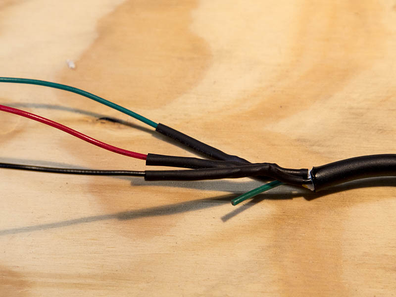
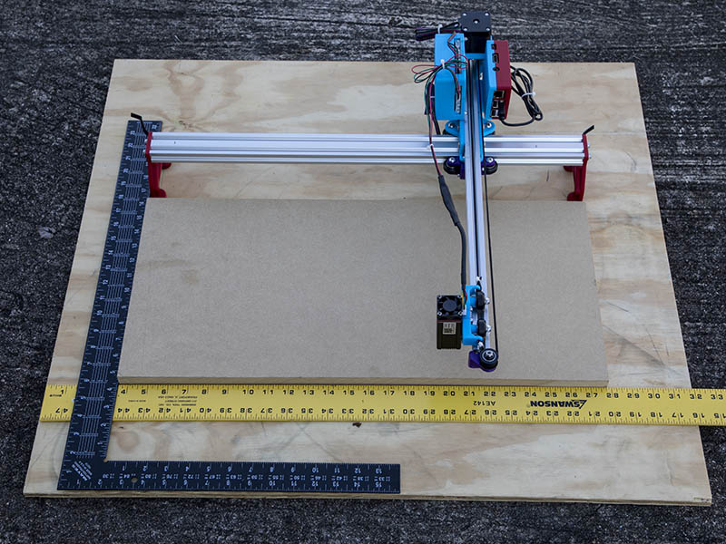
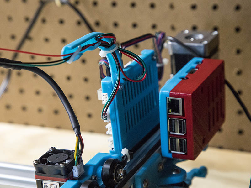
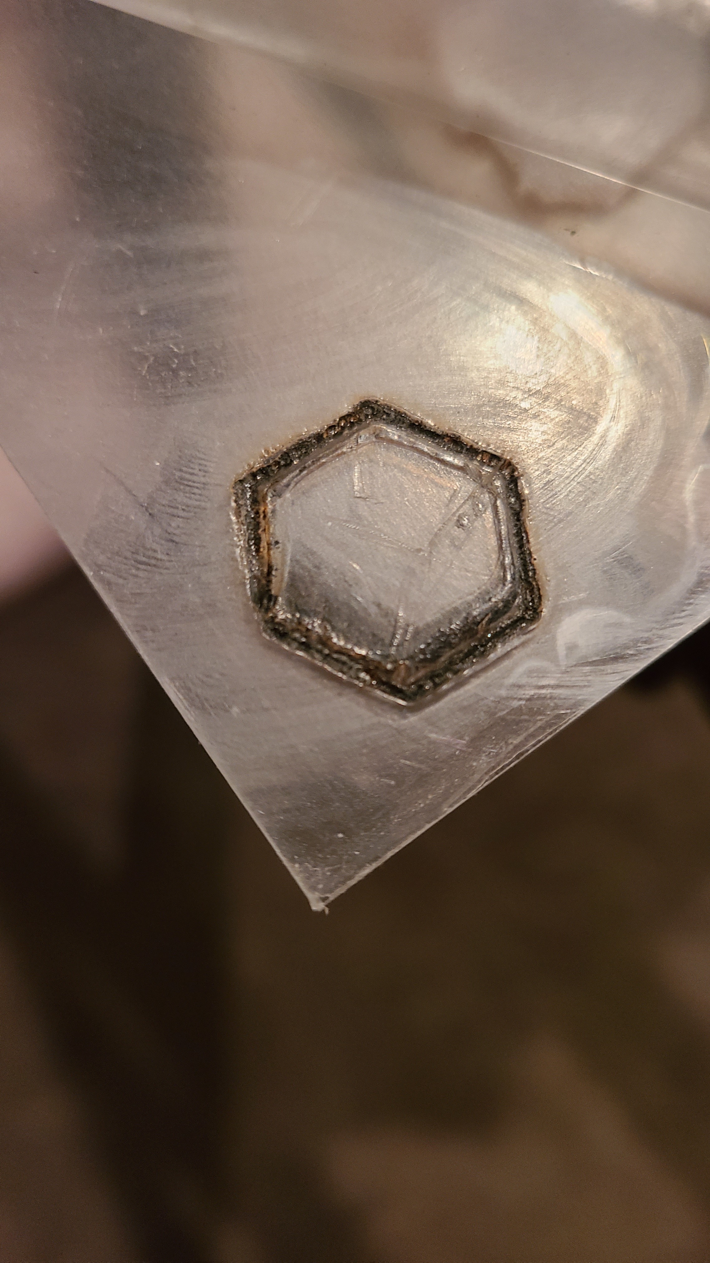
I finally got the wiring done and will probably do my 1st burn test tomorrow. I forgot to put heat shrink on the 1st wire before I soldered them together, but was able to pull that one out of the plug & put it back in after putting on the heat shrink. Luckily I only did that before soldering the other 2 wires. I set the VREFs on the DRV8825s before putting that case on. I had a spare piece of MDF which was a good size & if it is not too short a burn distance will use that as the flat surface to burn projects on. Here are a couple of photos.
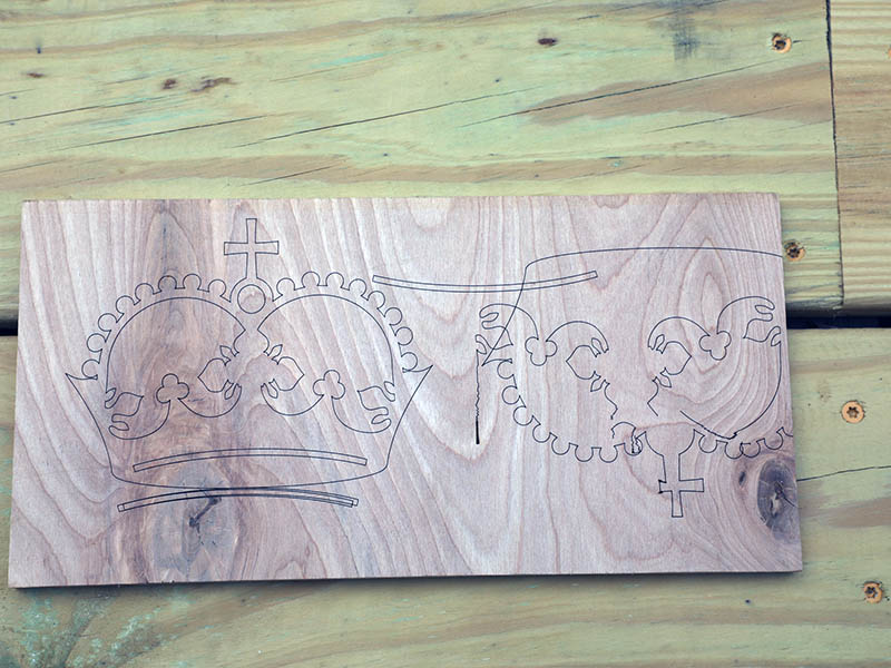
I was going to use .9 degree motors I had bought this summer, but they did not seem to want to move, so swapped them for the motors I was originally testing & everything is fine now. Will have to test those motors again on a spare board to see if they do work. I found the crown laser test gcode and ran that today. I had to change M106 S255 to M4 S1000 & M107 to M4 S0. I thought S255 was the high number, but was not burning much, so then tried S1000 & it looked good. The 1st test I was not watching it the whole time, but seems to have caught on one of the wires when moving. I will have to create some better wire management. Here is a photo of the test burn. Looks pretty sharp to me.
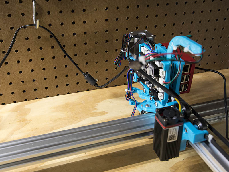
I added a wire management channel for the laser wire & seems to work good. It is attached to 2 screw connections on the controller board.
Here is a video of it burning an image using Lightburn. The image mode is Sketch. This is running at 100mm/sec & 90% power. Probably need to adjust those numbers. I used my 6 year old phone camera instead of my real camera to video this in case the laser was not good for the camera.

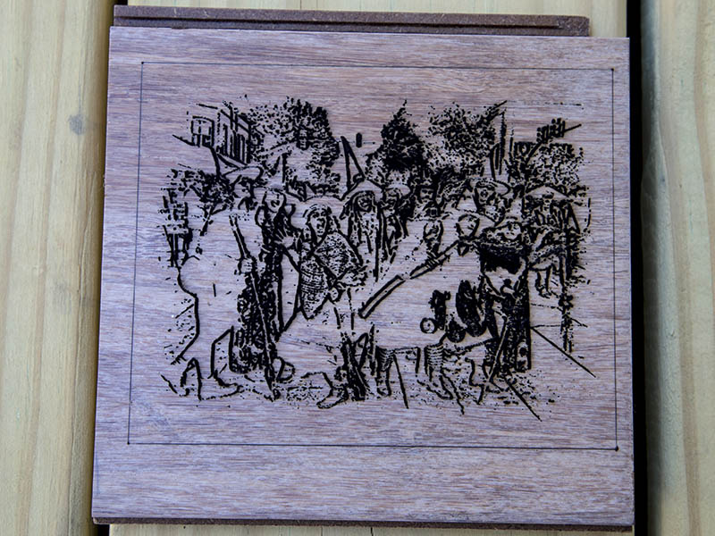
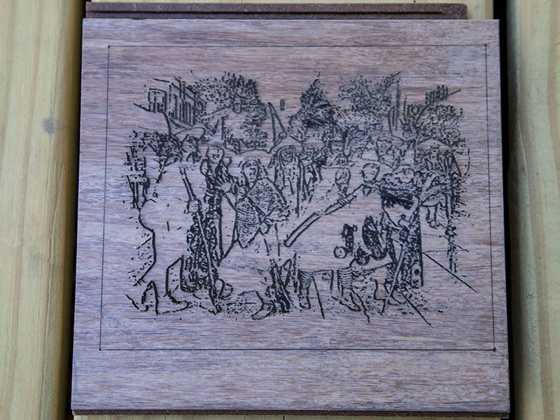
This was from a halloween photo from a couple of years ago of a group of witches. First photo was hot off the laser, the 2nd one is sanded a little with 220 grit. Looks like I have room to improve. I made the rectangle outline 5"x4"(127mmx101.6mm & it measures perfectly & diagonals are same length, so it seems pretty square. I probably should do a maximum size Rectangle to really test the squareness. This burn took around 2.5 hours. Probably could have run it faster and had finer detail.
I have the legs screwed down to the board & did notice that I can flex the end legs. It does not seem to affect the engraving though. I placed an order with Misumi today for the extrusions for an enclosure and added 2 -2080x400mm lengths to the order to use for the legs. Since I did have the height of that 2040 at 80.7mm, 2080 works out well. That will get rid of any flex & also make it possible to make this more portable. I can foresee putting this on one of the new deck boards in a corner or two & burning a design. I had first thought about using a couple of 2x4’s for the legs, but drilling and counter sinking for the M5 screws could easily be off. While I am waiting on the aluminum, I might work on a drill jig design for the 2x4’s to see if it work.
I just realized this morning that a pocket hole drill bit would be perfect for drilling these holes in the 2x4 & I have one. Will try that on my drill press after I make jig for it.
Covering with transfer tape or masking tape prior to running the laser job can help keep the soot off of the surface around the engraving. But then you have to pick it all off again…
Thanks for that info. After reading this, I did recall seeing that in a thread somewhere. Maybe it will stick to my brain this time.
I burned a grid 450mmx250mm with 25mm spacing on the plywood base for my engraver yesterday. My current maximum dimensions are 495mmx255mm. This was a good way to check the squareness. Putting a framing square on it, I can not see any problems. I measured the diagonals & they are 1-1.5mm different. Over a diagonal distance of about 515mm, that is close enough for me.

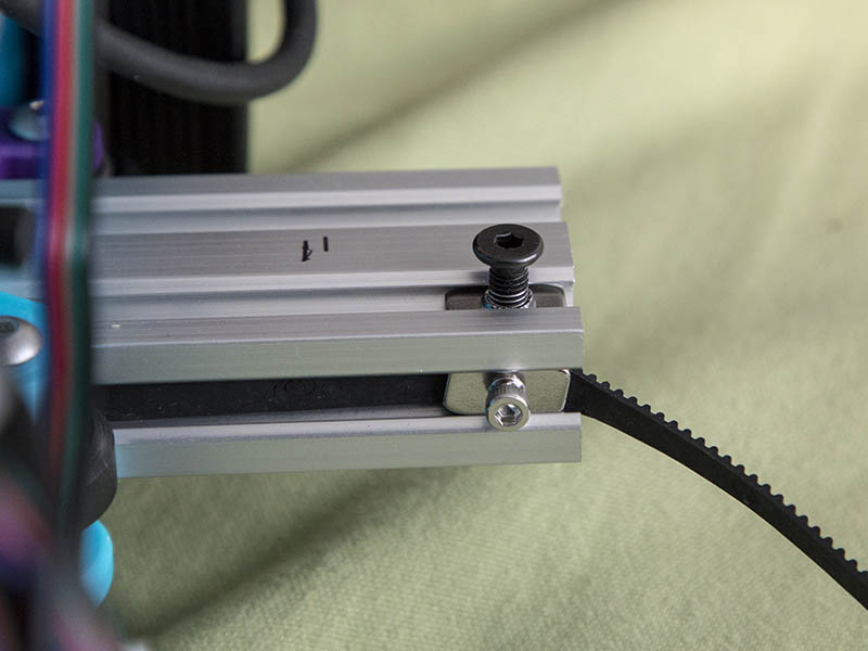
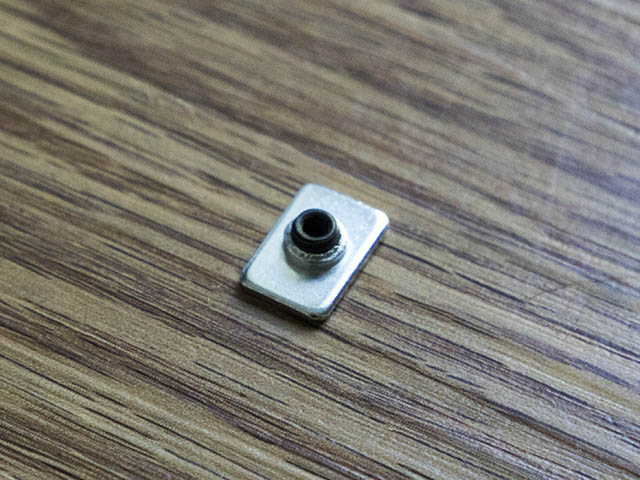
I changed the M5 T-Nut belt clamp to use a M3 T-nut which gives me another 2mm on each side. I actually had 499mm of travel on that axis, so this gets me over the 500mm mark.
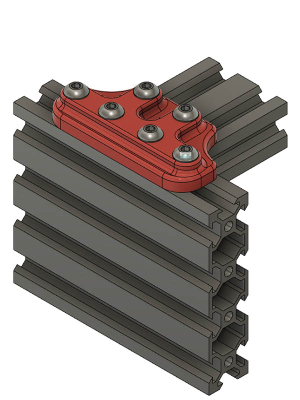
While I am waiting on the 2080’s to arrive next week, thought I would test the legs with some spare V-Slot I have. I don’t have any 2080’s, so I put 2 2040x250mm lengths together on each end. Cantilever is stiffer & this also gives a little weight to the legs so they should not have to be secured to a work surface. I used the plates that I had to worked the best.
I am not real happy with those plate, so am printing a 3D printed plate to see if that will work ok. I could always cut one out of aluminum on my sphinx CNC, but this plastic part might be sufficient for the task.
It’s starting to look like some sci-fi rail cannon!
If you look at Mike’s blog, the 7th message in his thread shows it looking similar to the Bird of Prey Romulan Ship from Star Trek.
As a note on M3 T-Nut idea, I think a better idea would be to use a short M5 set screw. The wheel on the carriage 1st hits the M5 head, so eliminating that and making it as short as possible seems the simplest solution to giving just a little more width.
Thought I had some M5 set screws but did not, so I went to local Ace store this morning & bought a couple of M5x5mm set screws & they do work perfectly & give me a little more width. I am now at 511mm (20.44") width along the 600mm 2040 axis. I started out at 495mm before making all these changes.
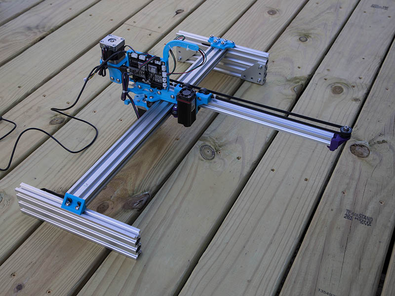
While testing the 2080 (2x 2040s) legs I realized the laser would hit one side before the wheels hit. I did not like that, so I changed to 2060. I thought about using 2060 before, but thought I would loose a little width. After looking at it again I realized I could make that work. Guess I should have waited a few more days before ordering those 2080 Misumi. I will just order another 250mm 2060 from openbuilds at some point or just leave it like it is. I do have 3 - 2060x1000mm lengths I was going to use for a delta printer a while back, maybe I will just cut one of those in half and be done with it. In the photo below you can see 2080 height on far side & 2060 on near side.
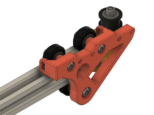
I want to get closer to the end of the cantilever with the laser so I can get closer to the edge of the deck at the house to engrave something. Right now I am at about 2.625" from end of cantilever to center of laser beam. I decided to redesign that carriage & add another set of mounting holes. Since that laser is not much weight seems like it should be ok. This gets me 2" closer to the end. I also have to redesign the end idler mount as that will hit it. I left the original 2 mounting laser holes in case I want to move it back to there.
I am looking at putting some sort of laser shield around my laser & came across this design.
https://openbuilds.com/projectresources/laser-shield-box-for-spindle-adapter.285/
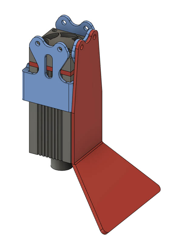
I am working on making a plastic part for this & see how it works before cutting some acrylic. I ordered some of that 3/16" acrylic shielding material from https://jtechphotonics.com/?product=445nm-laser-shielding . Can this stuff be cut with a diode laser or do I need to use my CNC router? I may just put a 12"x12" temporary wall of this in front of it while burning. I am being a lot more careful since I accidently forgot to have my glasses on when I went to check on it & glanced at it from 20 feet away for a couple of seconds before realizing I did not have my glasses on. No lasting affects from it, but don’t want to accidentally do that again. I am thinking just the 3d printed plastic shield might be all I need. Think I have it sized to be about 1" or so off the base. Any thoughts on that? I will probably put the acrylic shielding in place also. Here is the design I am working on. It is 2 parts. The blue part attaches where the laser mount is & the other part can go on any of the other 3 sides. Probably be difficult to focus if I put shielding on 3 sides.
While I can provide no data on that exact material, I bought a piece of Lexan from HD just to see what would happen. Wasn’t pretty.
Just ended up getting all melty and then I had little black soot floaties all over my lair. Don’t remember what settings I was using, but haven’t tried since.
After piddling with making changes to the carriage, end idler & adding laser light guard it is not working correctly. Initially it was not even firing the laser to start with. I tried my spare laser on this with same problem, so am thinking it is the controller board. I have not noticed any static discharge problem, but did still have motor wires connected to controller board while changing the parts & noticed the green light on controller board light up a couple of times when the motors moved. I should have disconnected them also as they do generate a little power sometimes when moving. I was going to hook up my keyestudio board, but need to make a better cable before testing that as the jumper wires at laser are to tight a fit. Here is a short video of what happens when I first connect the usb of the controller to my laptop. Almost sounds like a debug beep code for the controller. Anyone have a suggestion for this?
