GRBL limit switch alarm problem

You can certainly try an alternate protection technique like that, but again, I think you’re investing a fairly large effort to protect against a very small risk. Have you tried running the machine to its physical limit and seeing what happens? On mine the belt stretches a little (maybe 1 mm) then the motor starts skipping steps, which means the pulleys no longer turn, so theres no damage to the pulley or the belt or the printed parts of the machine. Just a sort of clunking noise from the motors, but no damage there either.

Many programs will allow you to do a “dry run” or “air cut” keeping the tool above the workpiece and moving the machine though the cut program as a test. This lets you be sure you’ve got the work in a place where the job will run without exceeding the machine’s movement envelope. Just another way to be comfortable running without endstops.

If you decide to try the relay, don’t put it between the stepper motors and their drivers. Disconnecting the motor when the driver is active will almost certainly permanently ruin the driver chip.

Many people (myself included) have an emergency stop on their machines. Exactly what stops depends on how you wire this switch. The grbl shield provides pins for what it calls an e-stop button, which resets the arduino uno. I did not use this. My e-stop button cuts off all electricity into the controller and machine, killing the spindle, arduino, stepper motors, and 2 accessory relays, same as if I were to pull the power cord out of the wall. I havent had to use it while a job was running, but I have tested it and I know when i hit it everything will stop.

I never felt the need to hit the e-stop when, before i got my noise problem fixed, the machine reached its limits of movement and started losing steps.

Another quick comment about safety. You cannot trust any machine with a spindle running at 20-30,000 rpm unsupervised. There are stories on these forums and numerous videos on the web of spindles crashing into workpieces and friction from the collet starting fires literally in seconds. All those chips make excellent kindling, and things escalate terrifyingly fast.

I’ve run several 3D printers, and am not worried about leaving the room while they run. I don’t leave the house, but will get a snack, use the restroom, answer a phone call, etc. I don’t currently have a webcam on any of them but am considering adding one so i can have a longer leash while big jobs run for hours.

I will never leave the room while the MPCNC is running a job. The job gets paused and the spindle turned off if I need to leave it alone for any reason for any length of time.

That’s a risk I just wont take. I have smoke alams and a nice big fire extinguisher on the shop wall right next to the door. I still won’t trust this machine (or any spindle or laser cutter) unsupervised.

2 Likes

After a near fire while sitting with my machine it happens that fast. I never go anywhere while its running

I found Alarm problem, it is from Stepper motor wires near to end stop pin that cause alarm, I think wrap the paper foil to the wires for end-stop switches and stepper motor.

that is good idea?

You’re basically making your own shielding that way. If it works for you, great. The endstop wires could be picking up the noise from anywhere along their length so you might not get results just shielding near the board. Personally, I would also be worried I would accidentally short something if the foil is exposed.

Hello @ttraband and everyone.

I found inside store room has bit problem with electricity, When I walked with
barefoot and go to store room, I start to test MPCNC and I touched metal case square of front the USB and I get little bit shock on my finger.

I put digital meter’s negative pin on top USB’s metal case and and I hold Positive pin with my hand, the meter showed me 105 Volt AC with small current output, that is mind blow.

The plug or main circuit breakers of store room don’t have an earth to protect from shock.

I realized that is big problem with CNC shield, i will call to Electricity Repair come to check.

1 Like

Maybe it wasn’t noise effect’s fault,

Interesting. I hope they get your wiring sorted out and into a safe condition.

1 Like

I’d where rubber soled shoes till it was fixed for sure

1 Like

Electricity done repair and he said earth cable was missed and he put new one.

So shock is gone now, I try all switches but it still error and it always showed me false alarm message and there are nothing solve and CNC shield is not good maker.

I decide put all switches connection E-Stop pin because there are no alarm error.

I want to know how to set CNC home without switches?

Glad to hear your wiring is sorted out. Sorry it didn’t resolve the noise problem in the endstop wiring.

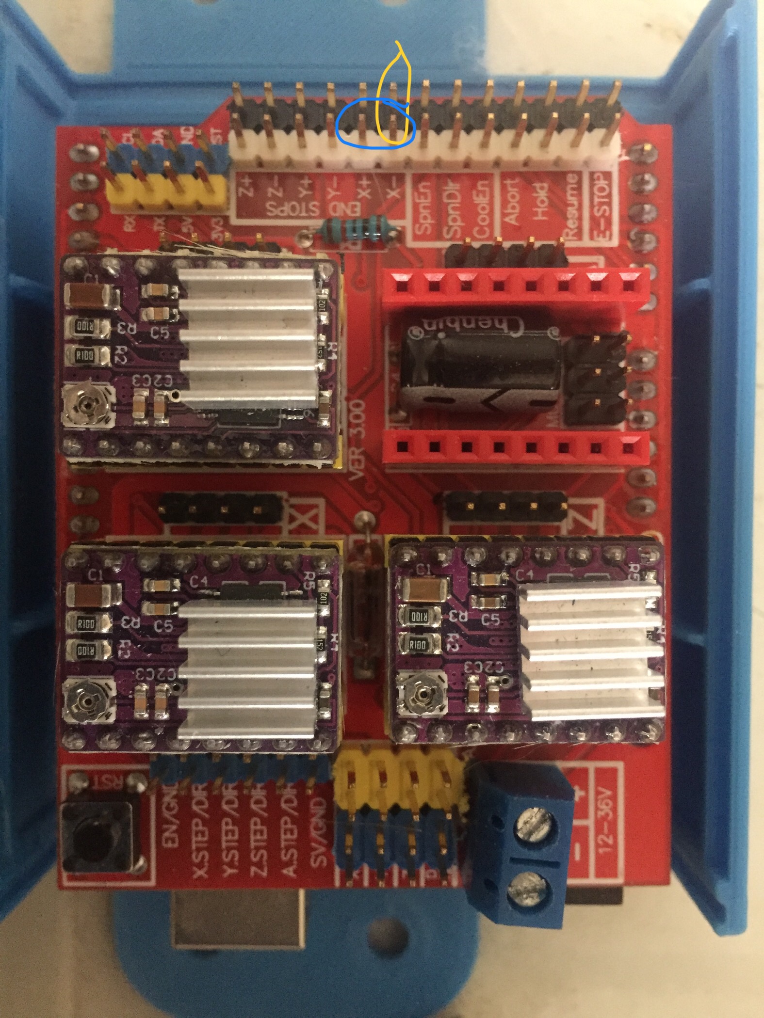
The eStop pin on the CNC shield is wired to the restart button of the Arduino. I don’t think you want your endstops resetting the microprocessor.

When running a CNC job, the job itself uses “work coordinates.” Limit switches establish “machine coordinates.” There are some tasks (tool changes, cutting multiples of the same job in a set of fixtures) where machine coordinates are helpful, but they are not needed to run a job.

To run without endstops, first make the following configuration changes to grbl:
$20 = 0 (disable soft limits)
$21 = 0 (disable hard limits)
$22 = 0 (disable the homing cycle)

You could also set $5 and $23 = 0 but that’s really just returning them to the “out of the box” defaults. They won’t have any effect on your work. Nor will $24-27.

By default, when the grbl controller starts up it begins in an alarm state. You can modify this by recompiling the firmware, but you can also just start each session by “unlocking” the machine. In cncjs there’s an “Unlock” button for this at the top right of the screen. You can also send $X from a console to kill the alarm lock. The machine should now be ready to move, using gcode commands or the buttons in your control software.

From here on out, you should be able to follow the instructions in the Docs sections.

Load the gcode into your gcode sending program. Install and secure the workpiece to the machine.

You’ll need to tell the controller the location where you want the job origin (X=0, Y=0 and Z=0) to be. This needs to be set relative to where you’ve physically attached the workpiece in the machine. Most often the job origin is set to the left hand corner (minimum X travel) nearest the front of the machine (minimum Y travel) of an imaginary box inside of which all the cuts are made, and with the tip of the tool just touching the top surface of the workpiece. Once the tool is in the desired origin position, execute the command
G92 X0 Y0 Z0.
This will set the work coordinate origins for all 3 axis to the current position. You can also do this one axis at a time, if needed. For example, after changing tools you may want to get the new tool touching a the top surface of the workpiece and send G92 Z0 to reset the Z origin without changing X or Y. Once the origin is set, you can move the machine around however you like, but when you start the job all instructions will be run relative to where the job origin was set.

The Crown gcode that Ryan has built as a test is a good example of this. When you load the gcode in a gcode sender that includes a preview, you can see that none of the lines in the crown touch the origin, but all moves are relative to the job 0,0,0 coordinates. Ryan has also included the G92 command in his pre-built gcode. This is not universal practice, as folks have their own preferred methods for setting up and starting their jobs. Options include telling the software you use to generate gcode for your jobs to include the G92 command, setting up macro buttons in your gcode sender, or doing it manually.

Once you’ve got the workpiece fixed in place and the origin set, you may want to move the tool up a little bit then move the machine to the extents of X and Y motion within the job (many gcode senders display this information) to be sure all the moves are completely within the mechanical limits of the machine before starting the job. This is sometimes referred to as an “air cut.” If something is out of whack, you figure that out without ruining a work piece.

Good Luck!

1 Like

I following this diagram to build GRBL Buffer for prevent EMI.

Im cofused which I connection GND from GRBL board buffer to XYZ GNB pin from Arduino?

See which is Yellow or Blue circle of pin + and - is correct to connection?

I build my own GRBL Buffer and the parts took from PC old power supply.

That board looks like a good solution.

The pins in the white headers (the blue circle in your photo) are the signal pins on the shield. All the pins in the black headers along that side are ground connections. You can verify that the black pins are all the same electrically with a continuity tester or multimeter on the Ohms setting.

Don’t forget that, with the latest grbl versions, SpnEN is really the Z endstop connection on the shield.

1 Like

Question

X+ Y+ Z+ that mean max of X, Y, Z, right?

Set homing will work with X and Y limit switches series or Parellel?

Do homing need limit switches connection straight to CNC shield without connection each other in paraellel or series?

Yes, the + means max for that axis.

The series/parallel question only matters if you want both min and max switches on an axis. Remember that the multiple X and Y pins on the shield are already in parallel.

Series for multiple Normally Closed switches on a single axis using the single connection on the isolation board you’ve built.
Parallel for multiple Normally Open switches on a single axis using parallel runs of wires between the switches and the isolation board you’ve built…

Personally, I do one switch per axis and use soft limits to protect the other end.

1 Like

I build GRBL buffer and it is work well with MPCNC and no more random alarm and now it is protect from EMI, Im very happy with it.

I want to know why soft limit is error alarm when I click button to move X Y?

Grbl refuses to start any move that will exceed the soft limit. It doesn’t stop a current move when the machine gets close to the limit, it prevents the machine from starting a move that it predicts will cross the limit.Have you set your travel distances with $130, $131, $132? You need to tell grbl how far it can go before soft limits can be effective.

To figure out the values to enter. I disable soft limits ($20=0), then home the machine and use my control program to move each axis to the point where it was close, but not actually hitting something at the far end, or in the case of Z the bottom. I rounded that down to the nearest .5 mm, added .1 mm and set that as the travel limit for that axis. That way, I can get to the point I expect, but grbl will prevent me from going further.

Once all the max travel distances are set, re-enable soft limits ($20=1), home the machine, and see that you can get everywhere you want to within the machine’s movement envelope.

A post was split to a new topic: Grbl endstop noise

This circuit is great

limit_switch_without_capacitor

but I would like to put 0.1 uF capacitor in it. Where should I put it?

I have several suggested options, but I can’t post them as new users can only embed one picture in post.
Should capacitor go on the left or on the right side of opto? Or Maybe on both sides? Why not on both sides?

This circuit with opto will be next to arduino - on the same pcb. Relative long wires will go to swtich.

I’m not running the opto-isolated circuit, just switches right to the pins on my CNC sheild. On my setup, I had to add capacitors between signal and ground to reject noise on my switch lines. I just pushed them into the connectors at the shield. I probably ought to do something more permanent but I haven’t had any problems so far.