I am working on building my lowrider2 and have a question about dual end stops and keeping the ability to probe the table. I have dual end stops working. For the Z axis, I am homing to the max (going up to home) so the machine does not try to ram a bit into the table. Is there a way to still use the probe to find the table with this setup? I tried a few things in the firmware and haven’t had success. I read a bunch of forum articles on here and didn’t find a great answer to fix this problem.
I tried to configure the DualLR firmware that way. It needs someone to test it. WDYT?
The 503 should have z home dir up, on pins Zmax and Xmax. And a z probe configured on Zmin. G38.2 should work to probe down and G28 Z should home up. The Z up switches should be wired C/NC, and the probe should be open until it triggers.
I’ll give it a try too. I actually posted this same question in the forums today as well. Once again @jeffeb3 to the rescue. You’re a stud bro. Much thanks.
Will try tonight. If I looked correctly this has x as short and y as long with dual. Should the code work if I comment out dual y and un-comment dual x or is it more complicated and I should reverse
Alright sorry for the delay. I did get it to work!! However…
For some reason I was not able to get your version of the code to compile. I had to change the firmware a little bit because I have my X as dual and my y as single so switched that and I had my endstops wired to match (extra was on YMax). I kept getting filename too long and could not for the life of me figure that one out (maybe I am using the wrong version of IDE (I am using 1.8.13)). I went back to Ryan’s code and made the modifications you did and it compiled fine.
In Configuration.h, it did not work for me to use Z_MIN_PROBE_USES_Z_MIN_ENDSTOP_PIN. Not sure why, but seems like the probe pin doesn’t get set. I commented that line out and changed the next line to use the same pin and it worked fine (#define Z_MIN_PROBE_PIN Z_MIN_PIN // Pin 32 is the RAMPS default)
For others with the same issues I outlined above and need to change Ryan’s dual endstop code here are the changes I did:
a. the ones outlined about
b. In Configurations.h change #define Z_HOME_DIR +1 (instead of -1)
c. make sure to update your bed size (not needed for this problem but caused me some grief)
// The size of the print bed #define X_BED_SIZE 1219 #define Y_BED_SIZE 1219
d. in Configuration_adv.h uncomment out #define G38_PROBE_TARGET
e. Change the setting of the dual stepper driver in Configuration_adv.h (ex X_DUAL_STEPPER_DRIVERS - uncommented, //#define Y_DUAL_STEPPER_DRIVERS - commented, and changed #define Z2_USE_ENDSTOP YMAX – my open one)
f. In Configuration_adv.h add: #define USER_DESC_4 “Probe Z min” #define USER_GCODE_4 “G38.2 Z0”
to Custom_User_Menus if you are using Ryan’s display
ps. the probe is wired on ZMin Endstop in my code
Let me know if you have any questions. Hope this helps the next person
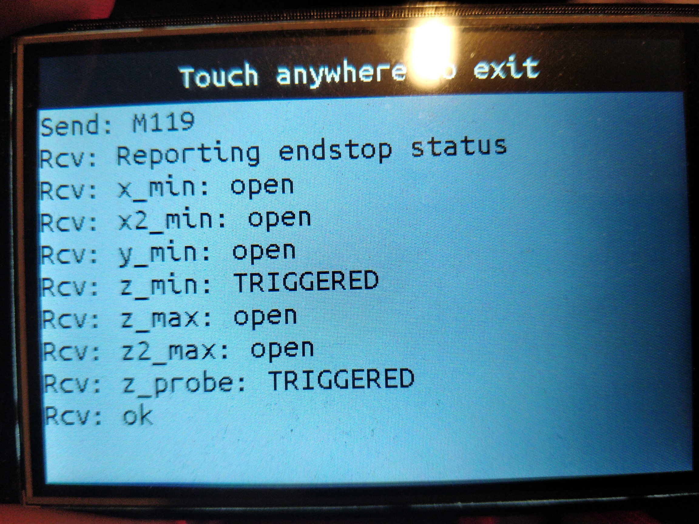
That makes sense. Thanks for pointing that out. I will install platformio. As I side note, you might need to do the Z_MIN_PROBE_USES_Z_MIN_ENDSTOP_PIN change to Z_MIN_PROBE_PIN Z_MIN_PIN unless that has been fixed in the new versions. In Repetier host the first one (that didn’t work for me) said zmin when doing M119. The second says probe (works) when doing M119. This was when I was using the G38.2 command.
Not directly but it did not work for me when it M119 said ZMin but did work when M119 said probe. I think G38.2 needs a “probe” to work. When I switch to Z_MIN_PROBE_PIN Z_MIN_PIN, I no longer had ZMin in M119 list (edit: oops was still there, just added the probe).
Here is the difference for me:
When it worked
15:29:04.956 : x_min: TRIGGERED
15:29:04.956 : x2_min: TRIGGERED
15:29:04.960 : y_min: TRIGGERED
15:29:04.960 : z_min: open
15:29:04.960 : z_max: open
15:29:04.960 : z2_max: open
15:29:04.960 : z_probe: open
When it didn’t work
13:36:17.677 : Reporting endstop status
13:36:17.677 : x_min: TRIGGERED
13:36:17.677 : x2_min: TRIGGERED
13:36:17.677 : y_min: TRIGGERED
13:36:17.677 : z_min: open
13:36:17.677 : z_max: open
13:36:17.677 : z2_max: open
Tested switches and seems to work with the following for me (rambo):
//#define Z_MIN_PROBE_USES_Z_MIN_ENDSTOP_PIN #define Z_MIN_PROBE_PIN Z_MIN_PIN // Pin 32 is the RAMPS default
Also, I had the Z2 stepper on the second Z slot on the rambo, but it appears this setup expects it on the E1 stepper.
Few things I can still used help on, I tried to convert from dual Y to dual X in the code, but I am still seeing a single X Endstop. Might flip my X/Y and test later tonight.
Also, the code resets to x0 y0 z200. Assuming this is because it assumes max Z before homing but wanted to verify this is expected.
Yeah. That second Z slot should not be used in any configurations.
I get confused. All of you seem to want dual X and not dual Y. Is that the normal? I guess it probably is… I can switch that easily enough.
Ah, yes. The Z max is set to 200. So when it homes, that’s what it should be set to. You can set the Z size to whatever you actually use, or you can just set up a macro for G28 Z and G92 Z100 or whatever your actual max is.
New to the lowrider, so I just though of the long axis as X, but am not sure what is normal (if there is one).
Update: Just realized that even though I had uncommented #define X_DUAL_STEPPER_DRIVERS, I missed uncommenting #define X_DUAL_ENDSTOPS a few lines later.
That change seemed to make the dual X work as I expected with two switches in my hand. Next step will be to mount the switches
When looking at a chart, the vertical axis is the Y axis, and the horizontal axis is the X axis. Your starting point on the chart would normally be the bottom left. The Lowrider uses these coordinates.
When using a CNC machine, the X axis is down the length of the table, the Y axis is the width, and the Z axis is vertical.
Source: Machine shop owner buddy of mine who was confused that I kept referring to the router plate and gantry as the X-axis.