Hi everyone. Just ordered pretty much all the parts to build the ZenXY table. The actual construction will be a simple box similar to a shadow box I recently built for a client.
See attached - shadowbox was not finished at time of picture, this is just a rough representation of what I’ll build.
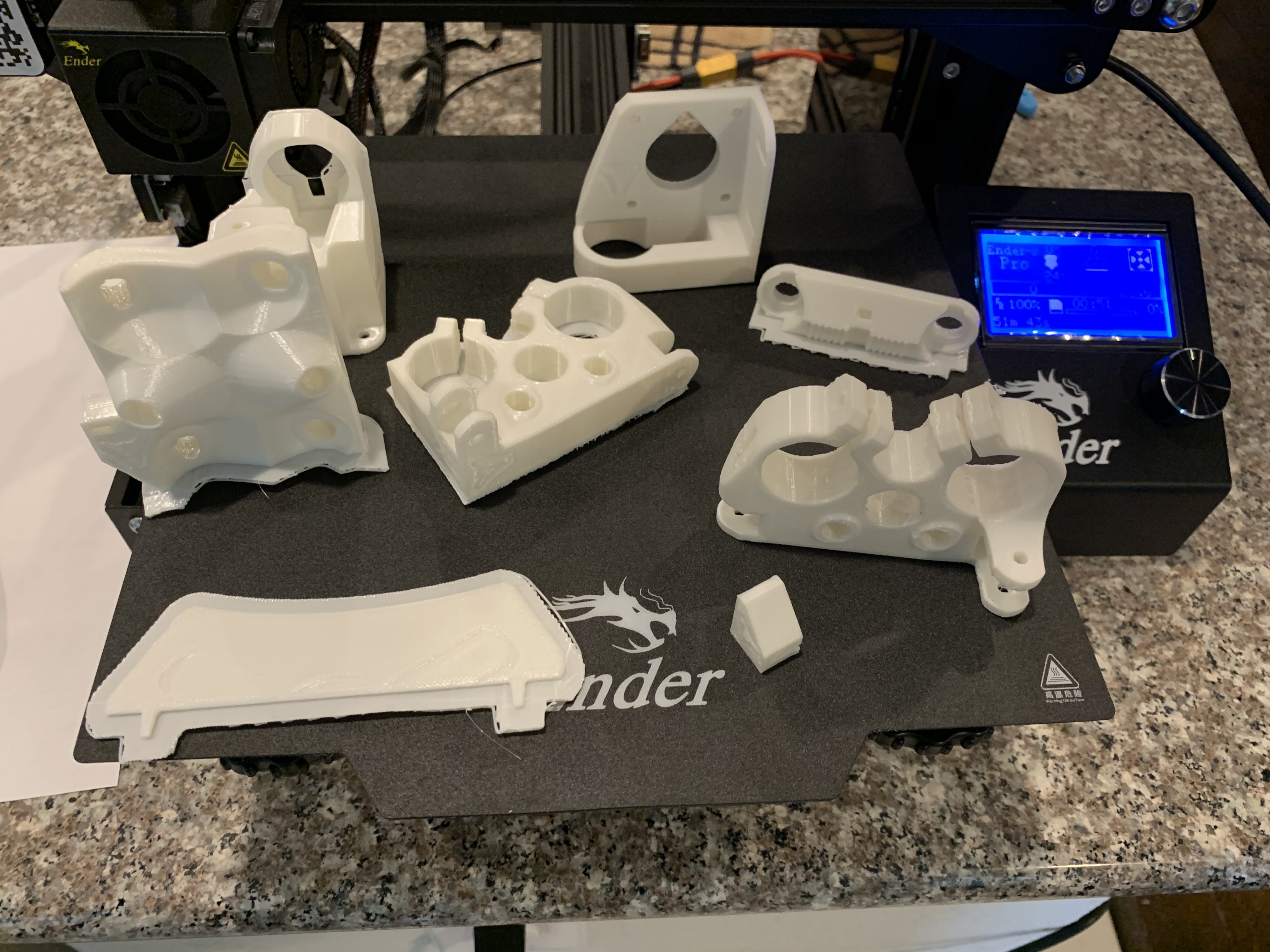
Currently I’ve printed 8 of the 10 parts. I’ll finish printing them today and pick up some conduit tomorrow. My plan is to get the mechanics working and then I’ll finalize the size and build my table around the base.
The construction will be the easy part for me, but I’ll be asking a lot of questions when it comes to programming the Rambo 1.3 mini. Please be patient with me.
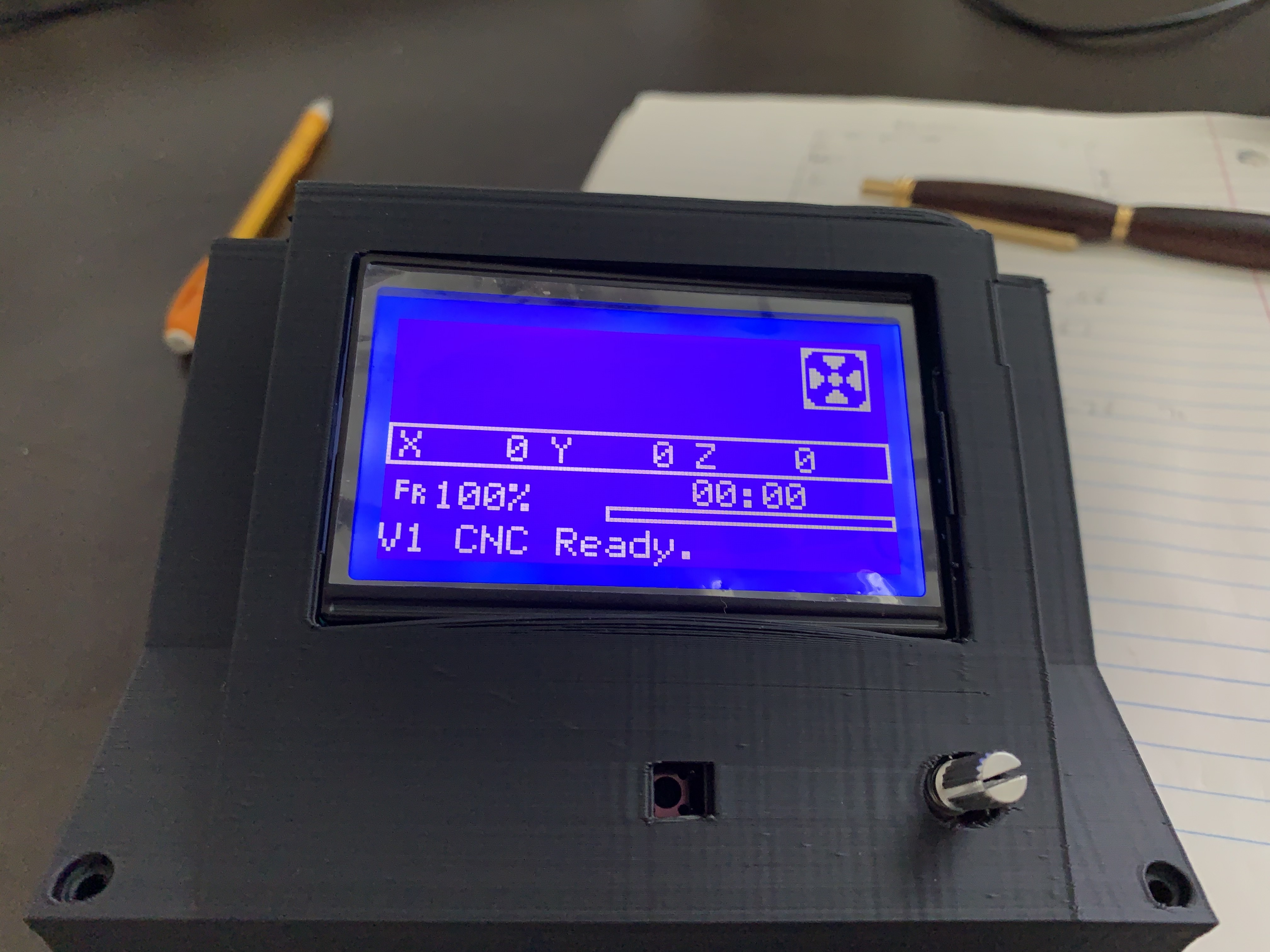
Received my Rambo 1.3, LCD, and power supply. Plugged it all up added a stepper motor and I’m able to control its movement. That counts as a success in my book. I purchased some conduit the other day and just need to cut it down to size. Right now I’m thinking of a 24"x24" surface, but I haven’t cut anything yet as I may go up to 29". I also need to 3D print a case for the LCD and the Rambo. Still no clue how you program things, but I’ll figure it out…Now that I know I can control the stepper motor I feel much better about actually building my table. Next up will be building the xy tracks from the conduit.
So silly me figured out I just need to use Sandify and setup some basic dimensions to start creating designs. I have my daughter working on coming up with some designs in her spare time.
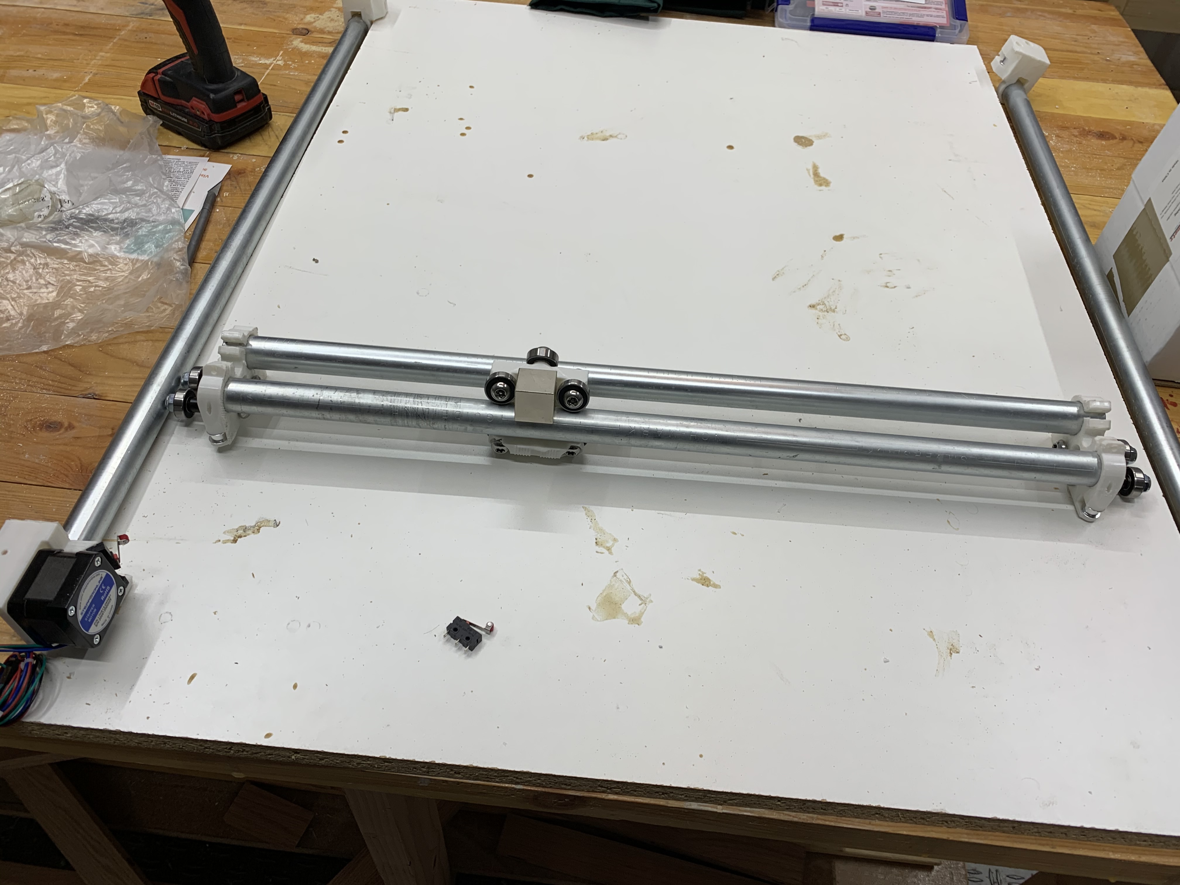
In the meantime I’ve cut my conduit down to size and assembled all my 3D printed parts. I’m hoping to have time this weekend to mount everything to a melamine board I have in the garage.
I also found a 3D printed arduino and display holder so I printed that. Fit was a bit tight, but some sanding took care of that in short order.
Once I get everything mounted and functional then I’ll move ahead with final design and build of the table. Right now I’m leaning towards oak, but I’ll see what the lumber yard has when I get to building the actual table. Maybe oak with a walnut inlay.
Appreciate the offer Kyle. I’ll probably need a hand fairly soon. I’m not much of a beer person, but I typically have a bottle of bourbon in the house.
I was looking on FB Marketplace and found several coffee tables with glass inserts for little to no $$ so I think I’m just going to find one of those instead of building a table from scratch. I find myself with too many projects, so if I can simplify my life then that’s what I’m going to do.
I have everything laid out on a board, but I’m not happy with all my 3D prints. I’ve gotten a bit better with the settings on the printer since I ran those parts and I’m going to reprint most of them. So far the three parts I’ve printed are much better.
Question regarding the limit switches: On the switch the outside pins are 1&2, the middle pin is labeled 3. On the Rambo I see where it’s labeled Endstops, but I don’t know which pin is which as it relates to the switch. Is it the same as the switch? If not, does someone know the pinout?
Also, I’m going to have to purchase a different magnet. I found a cheap square one on Amazon and it’s definitely strong enough, but unless I widen the support on the Center it won’t work. Oh well, I should’ve just ordered what was recommended.
Anyway, getting closer to doing the belt routing and testing. Assuming I don’t run into anything unforseen I’m hopeful I’ll be wrapping this up in the next couple of weeks. I’d say sooner, but life/work/etc seem to get in the way of play.
Also, after starting this I’m leaning towards building the MPCNC next…just gotta get thru a few other projects.
One last thought for the day…The printer I’m using is a Creality Ender3 Pro and it was only a couple hundred bucks. Creality has some that are cheaper. The Rambo FW looks identical to menus I see on the Creality. Theoretically I could’ve just purchased a kit from Creality and used most of the components, with maybe the exception of the belts not being long enough. I think the parts I purchased were a bit less expensive, but not by a lot. And it has the advantage of having the housings for the display and board with fans. Anyway, just a thought that occurred to me. Am I missing something?
The mini rambo is a tough board, and very versatile. I don’t know much about the enders, but if the firnware is hard to flash, or it is low quality, then the mini rambo is a better choice. But there are a lot of ways to do it. I use a grbl board. Pretty much any of them will work.
Which pin is +? I don’t see any markings to indicate what’s what.
No idea about the Ender3 quality wise or difficulty updating FW…I was just thinking it has 3 stepper motors, power supply, board, lcd, etc, all in one pkg. It was just a random thought…coming at this from complete novice and learning a bit and putting things together in my head it just occurred to me it would be a simple ‘pkg’ that people seem to ask about. You could buy the printer, print the parts, disassemble the printer and build your ZenXY table.
So interesting turn of events. I was in an multi hour meeting so I had the board on my desk to see if I could test the micro switches. I had the stepper motor plugged into the x axis and it was working fine. Using the diagram Jeffeb3 pointed me to I made up a couple small jumpers and plugged them into the endstop min/S being careful to avoid the + connection. I then wired the micro switch to the two outer pins - I used a magnifying glass and the pins are indeed labeled. Next I went in and moved the x axis and tried depressing the switch, but nothing happened. I tried the other direction, but still nothing. I reversed the wires on the switch, retested. Nada. Double checked continuity my little jumpers, tried a different switch, moved everything to y axis, etc. Still no joy so I set it aside for a bit. I just plugged it in and display looked normal, but even though I didn’t see the magic smoke, I smelled something…unplugged it. Checked everything visually, but didn’t see anything apparent and fuses didn’t blow. Plugged it back in, no smell, lcd looks normal, went thru the menus to control the stepper motor and get to the screen just fine, but I cannot get any motion out of the stepper anymore. Also the board is getting extremely hot. I’m guessing it’s cooked and I need to acquire a new RAMBO. Sigh.
What do you mean nothing happened? Did you have the 12V attached?
The endstops won’t stop motion. They are ignored unless you are homing. To see if they are working, use M119 and it will report open or triggered for each switch. There should be 5 for a dual endstop setup.
As for the gremlins/smoke. I’m not sure. They are generally pretty tough boards.
Good to know about the endstops only working when homing. I didn’t realize that…I just assumed they’d interrupt movement anytime they were depressed.
Yes power was connected. The LCD displays normally. I went thru the menus to Motion and selected X axis, which what the stepper was plugged into. I then attempted to move it 10mm, which worked previously, but this time no movement. I also moved the stepper over to the Y axis and same result. Also, the board is getting extremely hot for some reason, which it didn’t do before. I checked the motor fuse and it was fine. The other 5a fuse I checked, but it had to be fine otherwise the board wouldn’t have powered up. My desk is just a wooden desk so there’s nothing for it to be shorting on, yet like I said the board is getting extremely hot like something is shorting out on the board itself. I went ahead and ordered another rambo 1.3 out of frustration.
Interesting. Can you tell which chip is getting hot? A mosfet?, a driver? The main cpu? Did you try disconnecting the endstops? Maybe snap a picture first and we can look for issues.