I have a Rambo V1.4 board that I got preconfigured from Ryan set up for dual end stops (ill get to end stops later as i havent even tried to plug these in yet).
After searching the forums and net, i haven’t been able to determine if i have wired by board incorrectly.
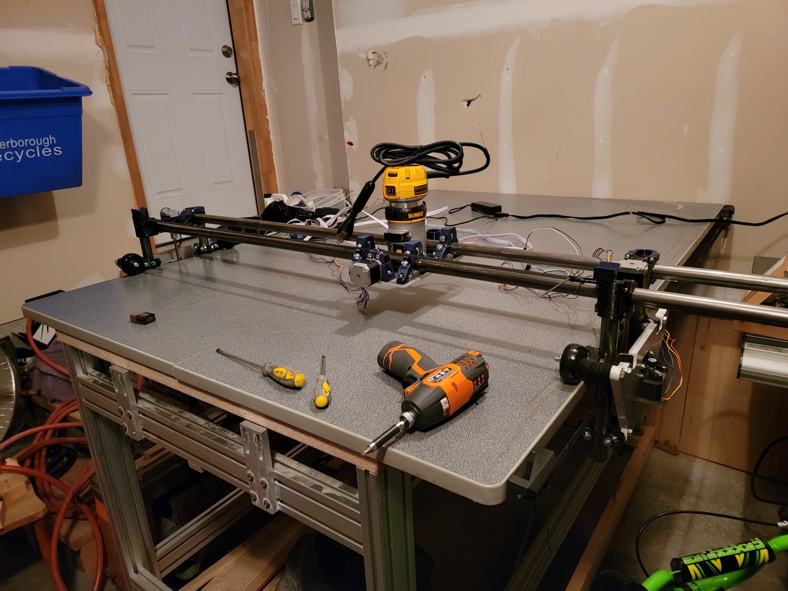
I have tested my machine and have movement along all three axis as “I” would suspect.
I have X axis going along the long span of my table (two motor - with belts).
I have Y axis moving along rails (one motor).
I have Z axis moving in the vertical.
From what I have read, I believe my wiring should be incorrect but as stated above, manual movements work as expected - maybe just luck?
my next question would be, how do i get the height of both Z motors to be aligned or does that come later with the G Code? I do have the touch pad/probe/sensor - but i know this is just to help located the tool before cutting. I find that the left side of my machine often droops after disconnecting the power.
Finally, what is the proper way to shut off the board/lcd? i have been just disconnecting the plug to the wall. is there an on/off switch that i am missing?
Thanks Jeff,
After some more reading (this page in particular: Dual Endstops Low Rider - V1 Engineering Documentation), it looks like item 5 for the rambo is the scenario I am seeing. I believe my X and Y axis are flipped for whatever reason.
EDIT: I reflashed using the firmware suggested above and rewired. Movements are now aligned with the write ups (x and y are now flipped) and the z drives seem more powerful.
I see many people confused about the LR2 axes. I borrowed this image from the LR2 instructions and added the X and Y axis arrows to it. Many people assume that they’re standing beside the machine with the gantry rolling from the left to right, instead of away from you and towards you.
In this image, the tool is close to the 0, 0 position.
Thanks Dan,
your diagram aligns with Ryan’s description as well.
i was just confused as to why my x and y drives were flipped.
that problem is solved, and now on to the next!
Another question. When using endstops on z axis ( vertical) does the homing sequence along z move upwards (postive Z)? Mine is trying to move vertically not sure if that’s the correct behavior.
I’ve always wondered how Z homing would work with the LR. I typically use a small carpenter square, one edge flat on the spoil board then lower the Z assembly until just touching with the router close to 0,0. Then I’ll move X to the max positive value and adjust the right side Z leadscrew by hand until the router mount is touching again. Move the router back to 0,0 and double check Z height.
Is there an easier way you know about?
I’ve been meaning to draw up a rest that I could slip under the X rails so that when the steppers die and the X gantry falls, it rests level. But, alas, I choose the hard way…
With the LR2, in order to use homing to square the Z axis, it homes to the top of the travel, but goes down when using the touch plate to determine Z=0
Homing in this case is more accurately squaring the machine. To do this, we need to have a consistent spot to go to where we can be assured that both locations are an equal distance from a reference point.
To home Z downwards would be difficult, to say the least, unless you are always going to have the same tool in place (like an extruder, for example) and you would need to test in 2 known locations to be able to level the motors. Easier to place 2 switches in known locations, where you can always get there, and never need to go past. Going towards the table, a longer tool will prevent you from getting there, and a shorter tool might require you to go past the switches, or cutting into the spoilboard to be sore you go through your material.
Thanks Dan,
i agree that this is more of a squaring process rather than homing. Squaring is exactly what i am trying to achieve! I also ordered the touch plate for homing prior to start the cut (which i still havent gotten around to yet). Ill need to get some parts designed or downloaded to mount the switches for z squaring.
Appreciate the help!
FWIW, I don’t use dual endstops on my LR. I just start the motors while the sides are resting on the bottom. My LR has a 4’ span. I can get within a mm. That’s pretty good too me.
Pick up a pair of inexpensive mass-produced items while you’re cogitating on your rest design. I used to tomato paste or soup cans to level the two ends of the X axis on my Prusa clone before I upgraded to the version of Marlin that supports auto Z levelling. They were identical in height to the precision available on my (admittedly not stellar) digital calipers.
Thanks Jeff, i also assumed that starting in the fully lowered position would be suitable for leveling. However, since i already have the equipment purchased, i figured why not add the functionality with the end stops (if it ends up being to much of a pain, i can always disconnect).
Tom i also agree, my next thought would be to 3d print a cradle or spacer that i could put on both ends of the X axis tubing. they would help to level but also prevent the carriage from bottoming out in the z direction. when i disconnect power, one of my steppers always wants to bottom out and im not sure why. as such, my machine always sits skewed after powering down.
I worry about that in theory, but in practice, I’ve found that they’re definitely close enough.
Even when there’s a measurable difference (One has too much “squish” in the first layer, for example) the actual difference becomes irrelevant quickly.
Even then, if you use the X or Y axis for your more precise measures, you’ll be accurate to within one motor step for sure, and almost certainly better than that. Chances are that your accuracy is the accuracy of your filament, adjusted for your nominal extrusion width. Better than my calipers at least.
So i have run into a new issue.
I can home X, however when trying to home Z, only the E1 (Z2) motor will move until the end stop is actuated. I have the Z2 drive connected to E1 on rambo V1.4 port and the end stop connected to the Xmax port.
Z1 (which wont actuate while homing) is connected to the Z port on the rambo, and its end stop is connected to the Zmax port.
Ive ensured that end stops are not using the positive terminal(S and - only).
On a side note, if I try to move any axis of the machine, it works as expected.
Could this be a damaged endstop, damaged board or something like software/firmware or just plain old user error?
My Rambo V1.4 was recently flashed with V1CNC_Rambo_DualLR 2.0.7.2-2.0.7.2 / 510.
Sorry Dan, unfortunately I haven’t gotten as far as looking into code (I wanted to get the end stops wired and parts printed/set up before starting to learn the code/commands). I have yet to read into this portion of the low rider. All movements/commands have been through inputs via the hand held screen.
Edit: i can access the code via Visual Studio Code and the platformio extension. when i do a cntrl F for M114 no results are found. I did not edit the this code, so maybe that line needs to be added?