LowRider-inspired Foam Ripper

Alright! Printed new spacers, eccectrics, and carriage plate (to accommodate the eccentrics). Got it all installed and reran the crown plot. Much better… all the closed shapes closed up nicely.

It’s still not the sturdiest of machines but this is the heaviest load it’ll see and I’m good with the improvement. I now need to run a few of Jamie’s rulers to check the calibration… and then start looking at a laser mount.

– David

1 Like

Played with the pen a bit more last evening. Did some of Jamie’s rulers for calibration of the steps/mm for the X and Y axes…

It seemed that the Z-axis might have been acting a bit weird… and the little stepper motor was running pretty warm so I set the Vref on the Z-axis down to 0.15 volts. I then tried a SquiggleDraw Yoda which seemed to come out okay…

I’ll have to keep an eye on the Z-axis for a while.

And today, while the laser mount is printing… I started looking at the laser hookup to the Keyestudio CNC board. The key for Grbl laser PWM is to see where pin D11 of the Nano goes… usually to the “Z-min” pin on the board (unless there’s already a dedicated laser output). Sure enough…

The yellow wire in the foreground is the +5v PWM pin (marked Z-min on the board) for controlling the laser intensity and the red and black wires just behind it are the +12v motor/laser power. These are the 3-wires that combine in the 3-pin connector on the 2.5 watt Eleksmaker laser controller…

Later.

– David

2 Likes

Decided to go for it. The laser seemed to be functioning properly and things looked really good for a while…

until… sadly – and quite unexpectedly – the raster exhibits skew in X as it progresses from bottom to top. To top it all off, the raster also seems compressed in Y and prematurely “finishes” without ever doing the dark top border and the profile cut (as on right in last photo). Obviously, a few things I need to go look at.

The message seems quite appropriate, don’t you think? … “I shall endeavor to persevere.” :stuck_out_tongue_winking_eye: :thinking:

– David

3 Likes

So that image was created entirely with the laser? That is pretty cool.

Yes. I used Lightburn to process the photo and generate the gcode file. In this case, I simply used the same gcode that I used to do the comparison photo on FoamRipper. Much credit goes to @Bulldog, over on the Lightburn forum, who’s helped a bunch of us greatly increase the quality of our engravings… on chipboard, wood, and ceramic tile.

1 Like

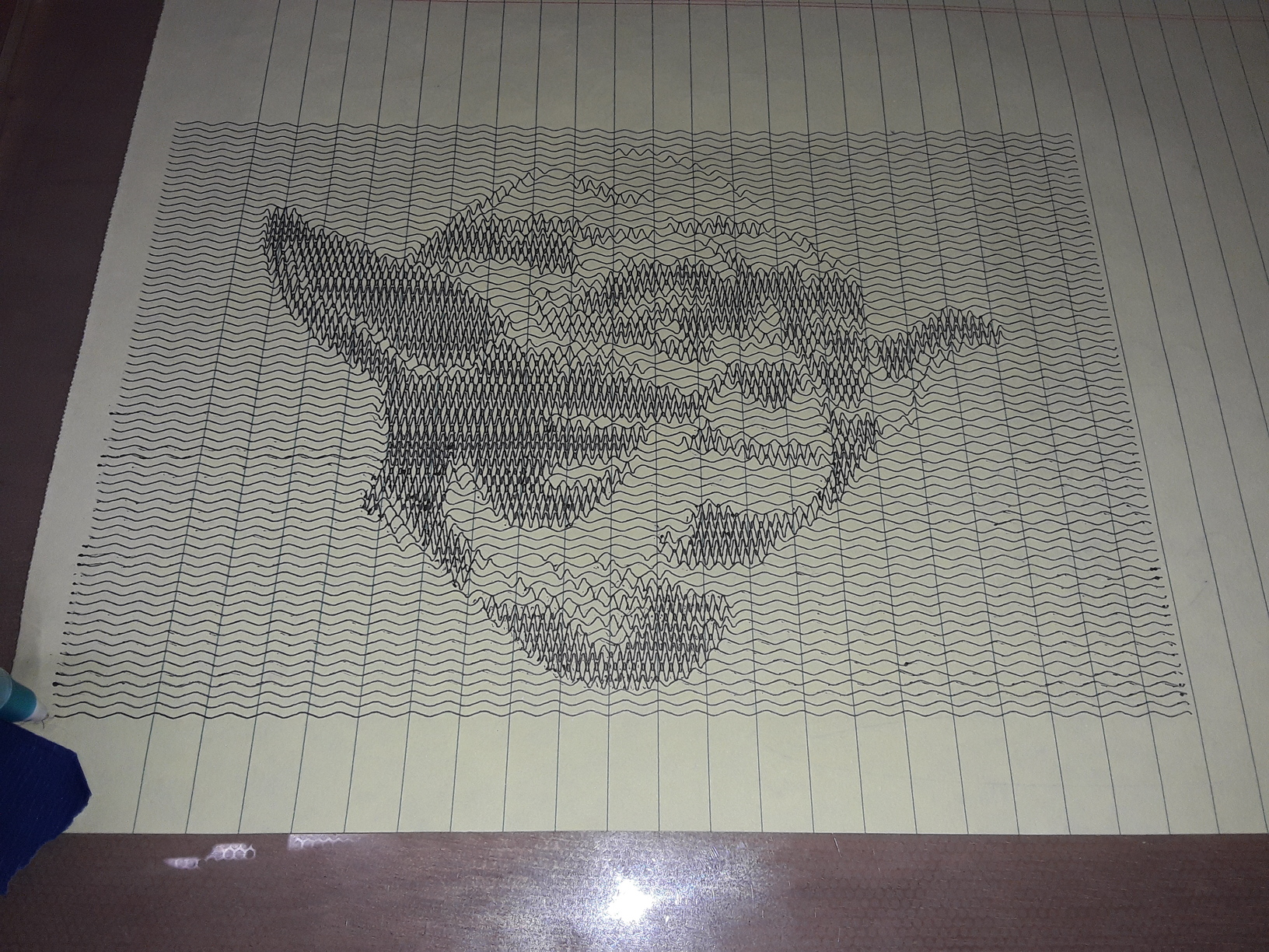
When last I left off I was astonished at what I was seeing… a skewed raster image. TBH from the beginning, I fully expected to have the put training wheels on the machine to keep it from running off the side of the road. What I didn’t expect was that it would gradually creep down the road in the same direction it was traveling.

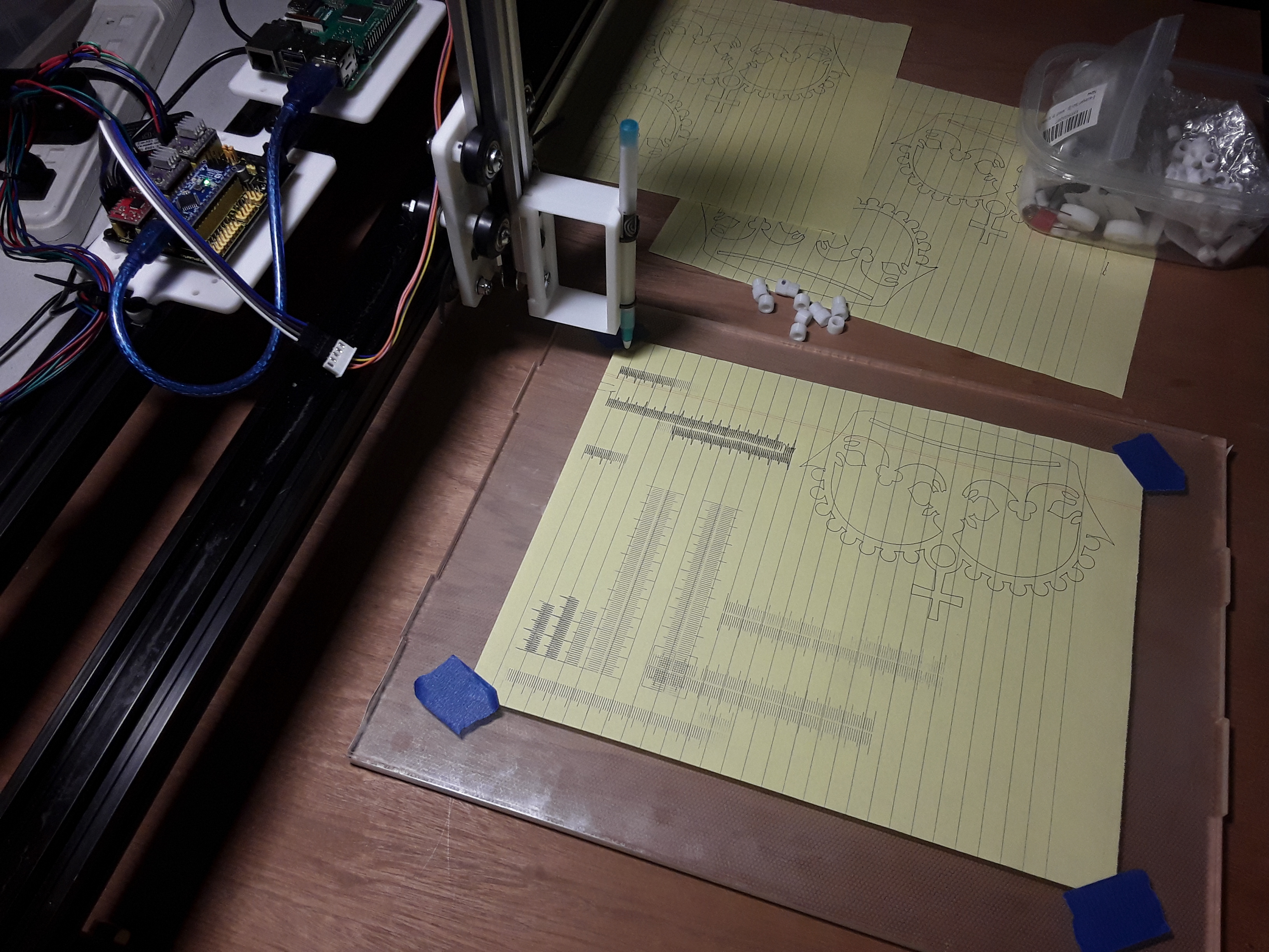
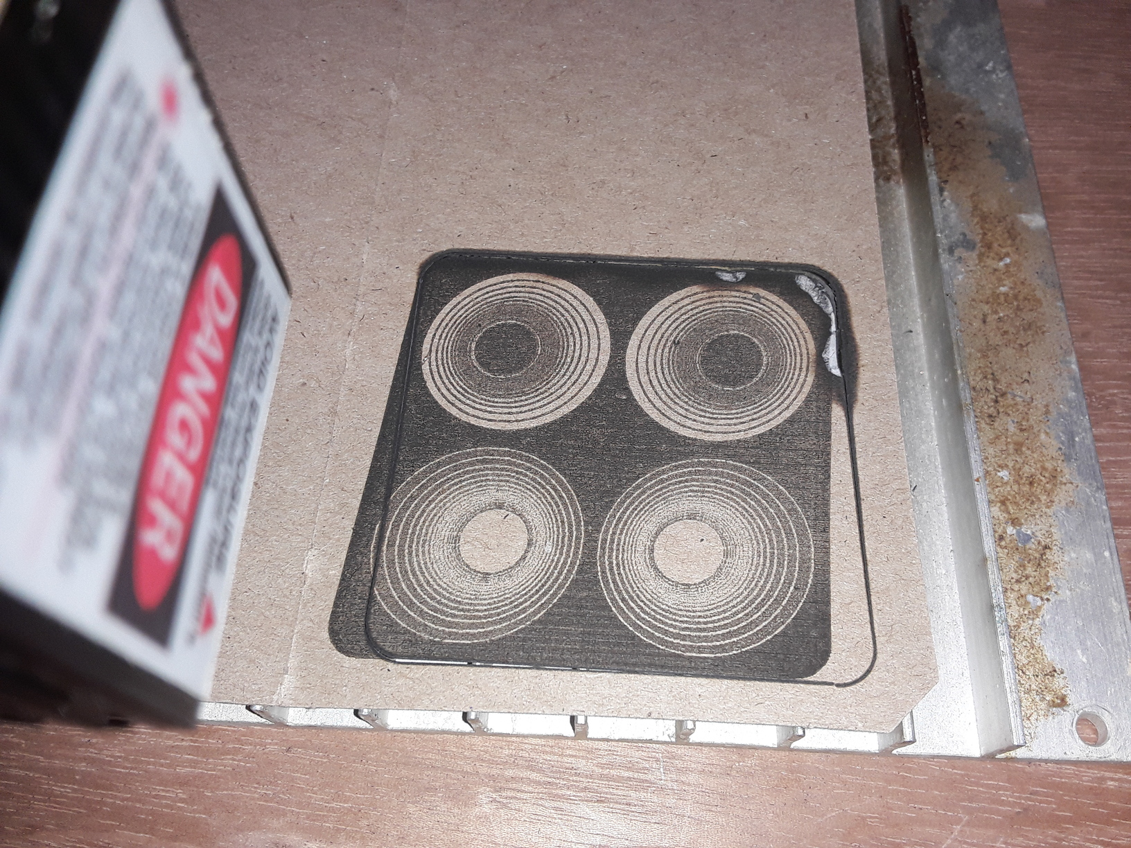
So, after pondering things half the night – microstepping, dpi, etc. – I started not-so-fresh this morning. I decided to use a smaller image and try again. This ran to conclusion, complete with the expected raster skew… and kinda surrounded by a perfectly square vector/profile cut! Whut tha… ???

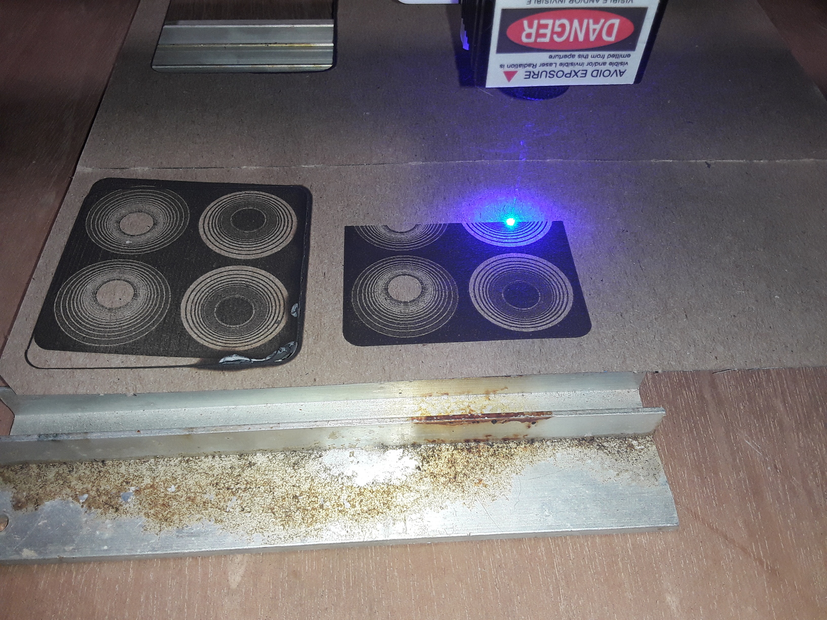
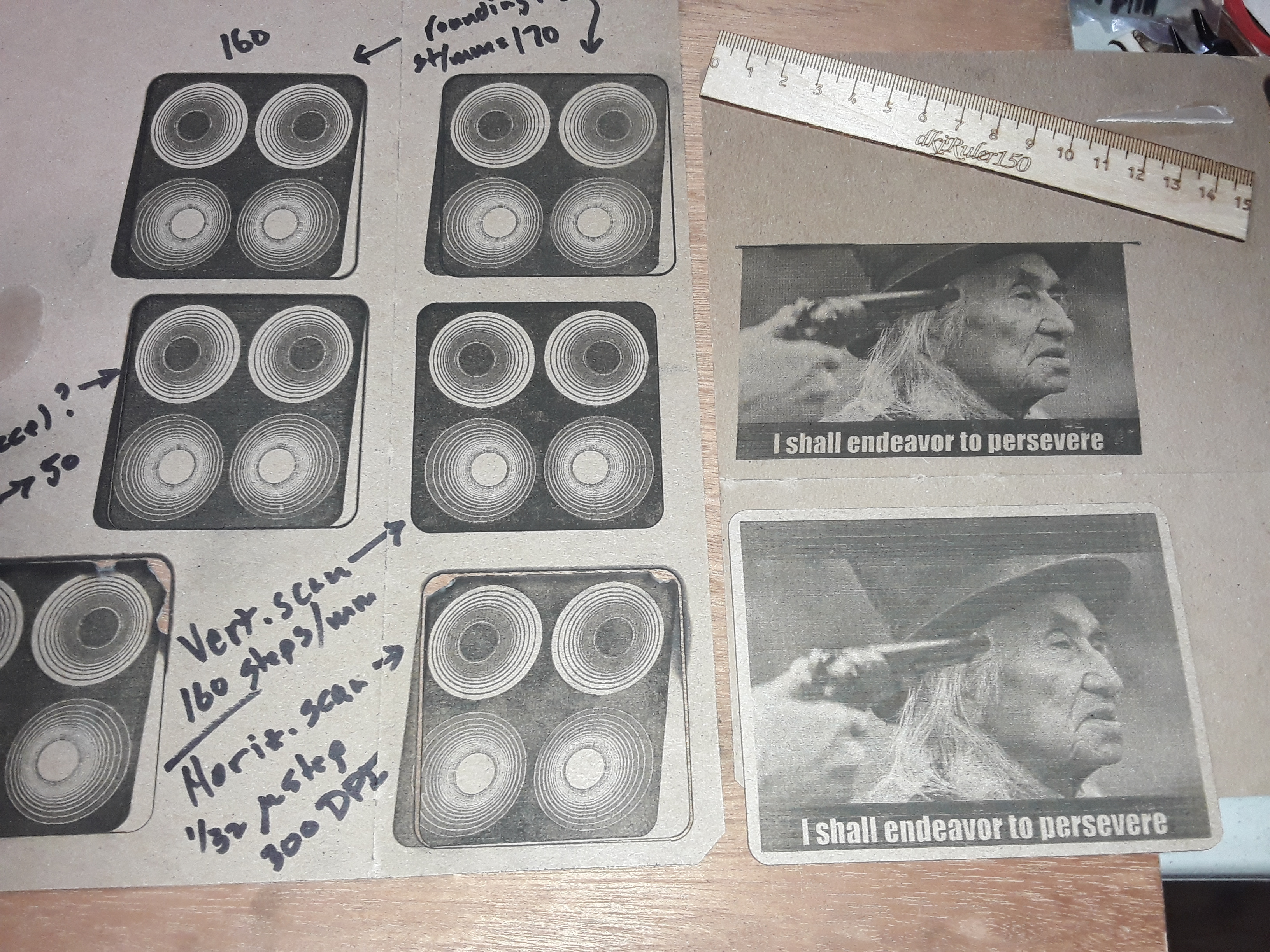
So, I decided to try a vertically scanned image to see what I could see… and fully expected to see the image skew along the Y axis this time. But, surprisingly, I got a nice, square image out of it…

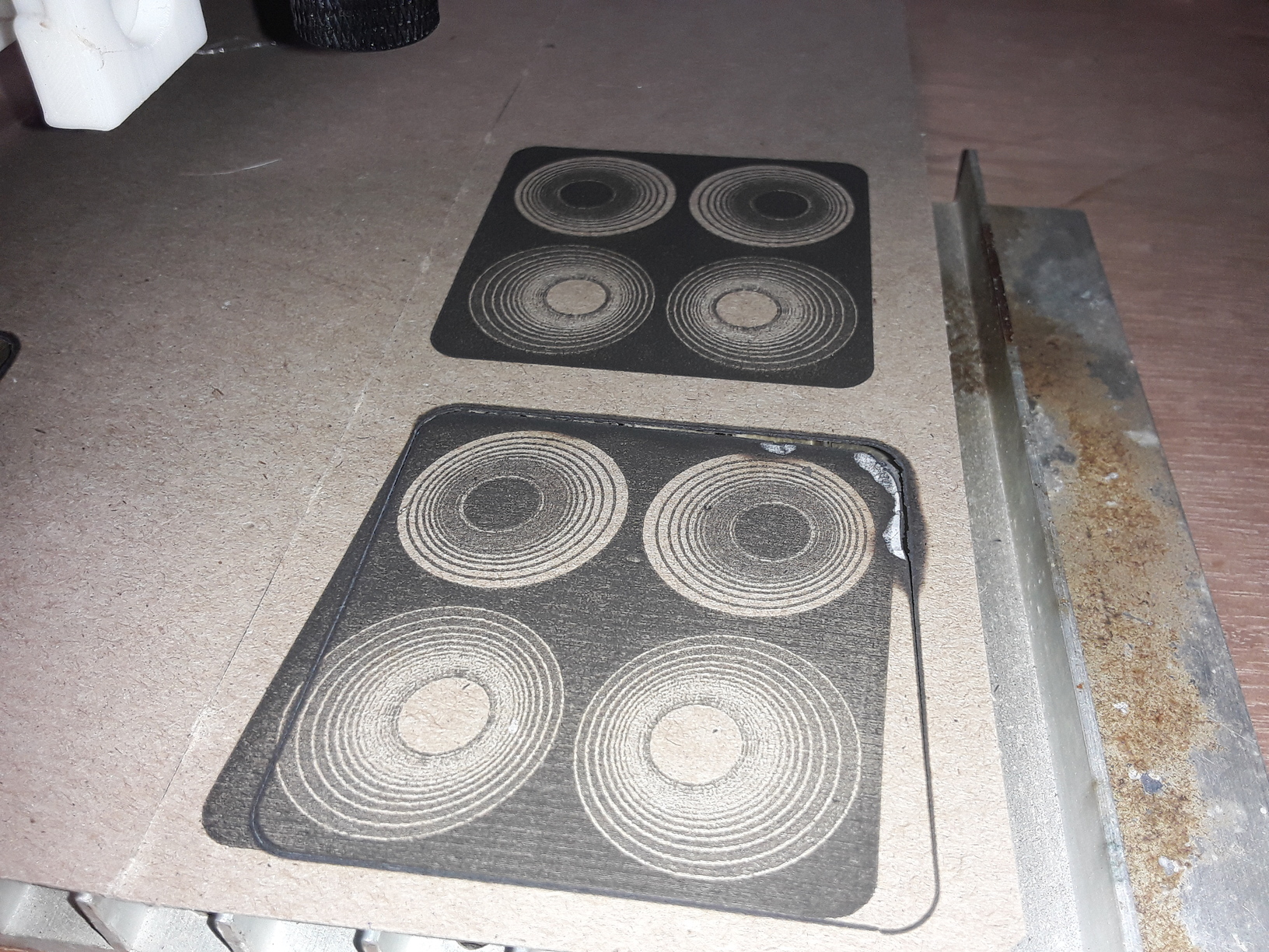
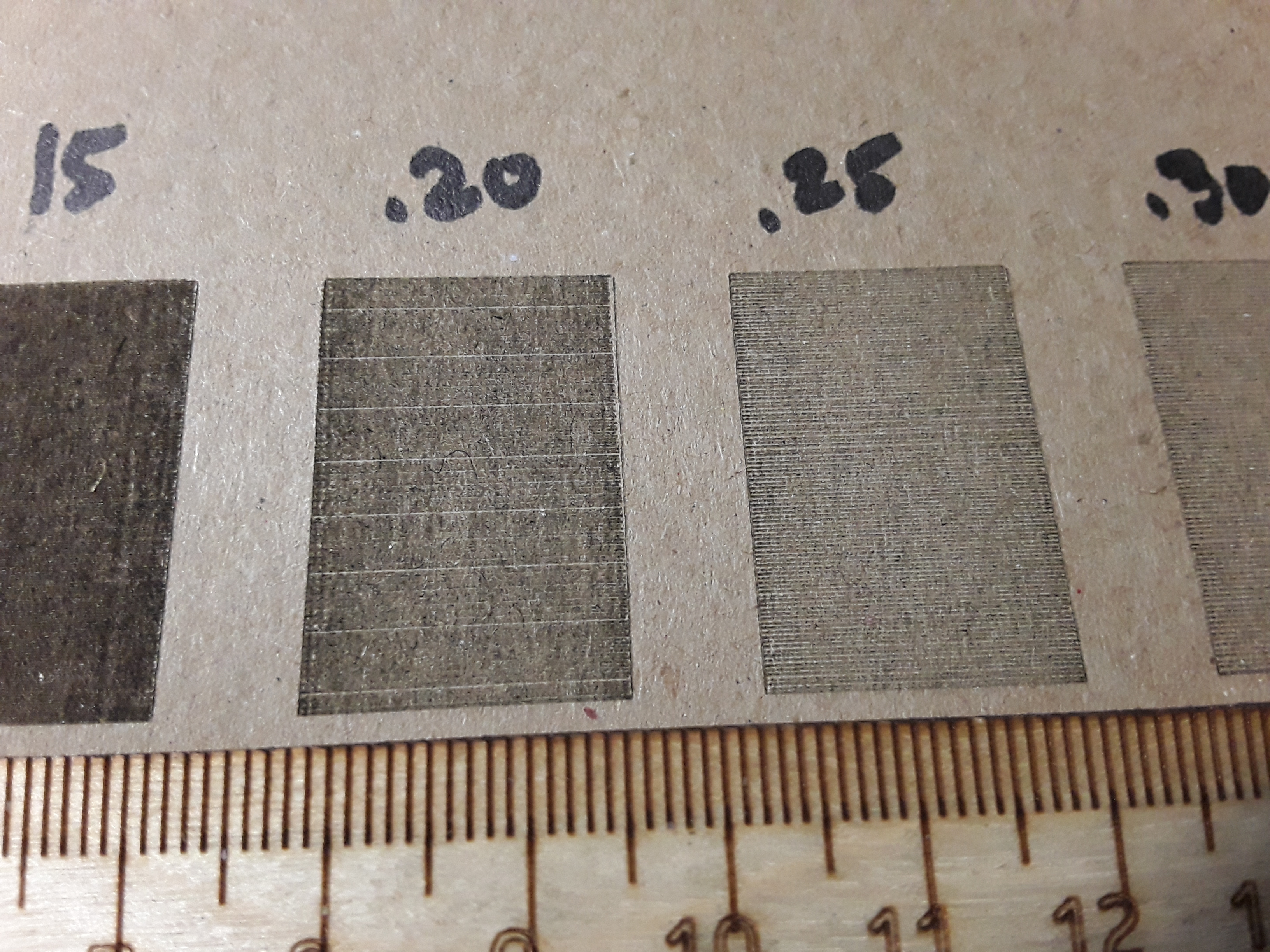
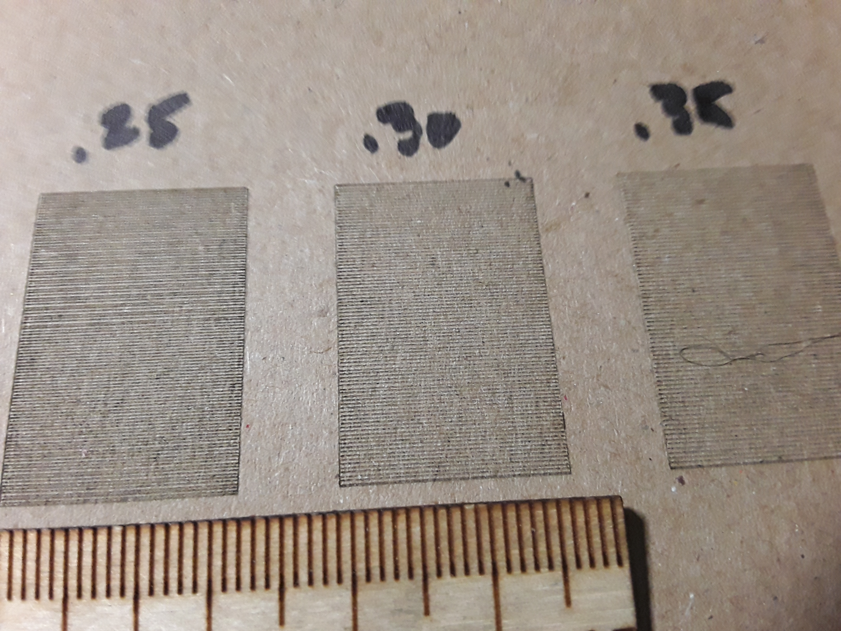
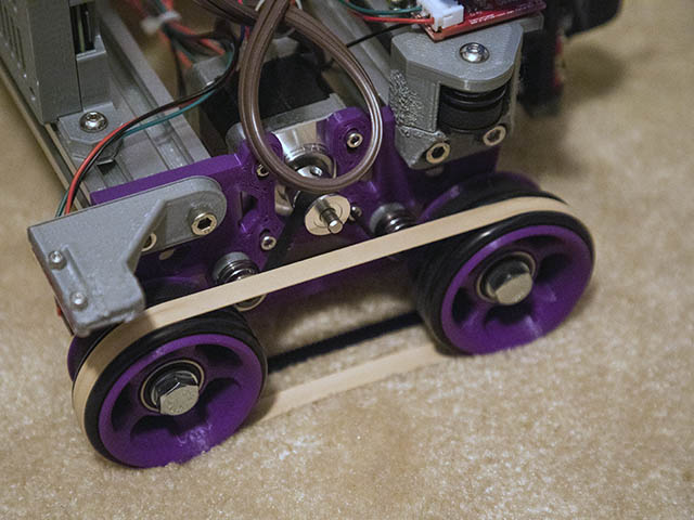
Of note, my X-axis is the direction the tractors roll… and where the skew takes place. Since these have printed 78-tooth pulleys affixed to the wheels, the steps/mm setting is pretty ugly – 169.473. In the Y-axis, things are cleaner… motor, pulley, idler, and GT2 belt… steps/mm is 160.000. Since vertical scanning made a dramatic difference, I then began to suspect “rounding errors”… with the poor, little Nano just unable to keep up. So then I rounded the NASTY-looking 169.473 to 170.000… and then 160.000… and I still get the skewed images (top two of the middle 5 images)…

It does appear there may be a little less slant to the top two images but it still ain’t right. So, grasping at straws, I began to wonder if it was possible I was “slipping the tires” a little and changed the X-axis acceleration from 100 to 50… the middle-left image appears virtually the same.

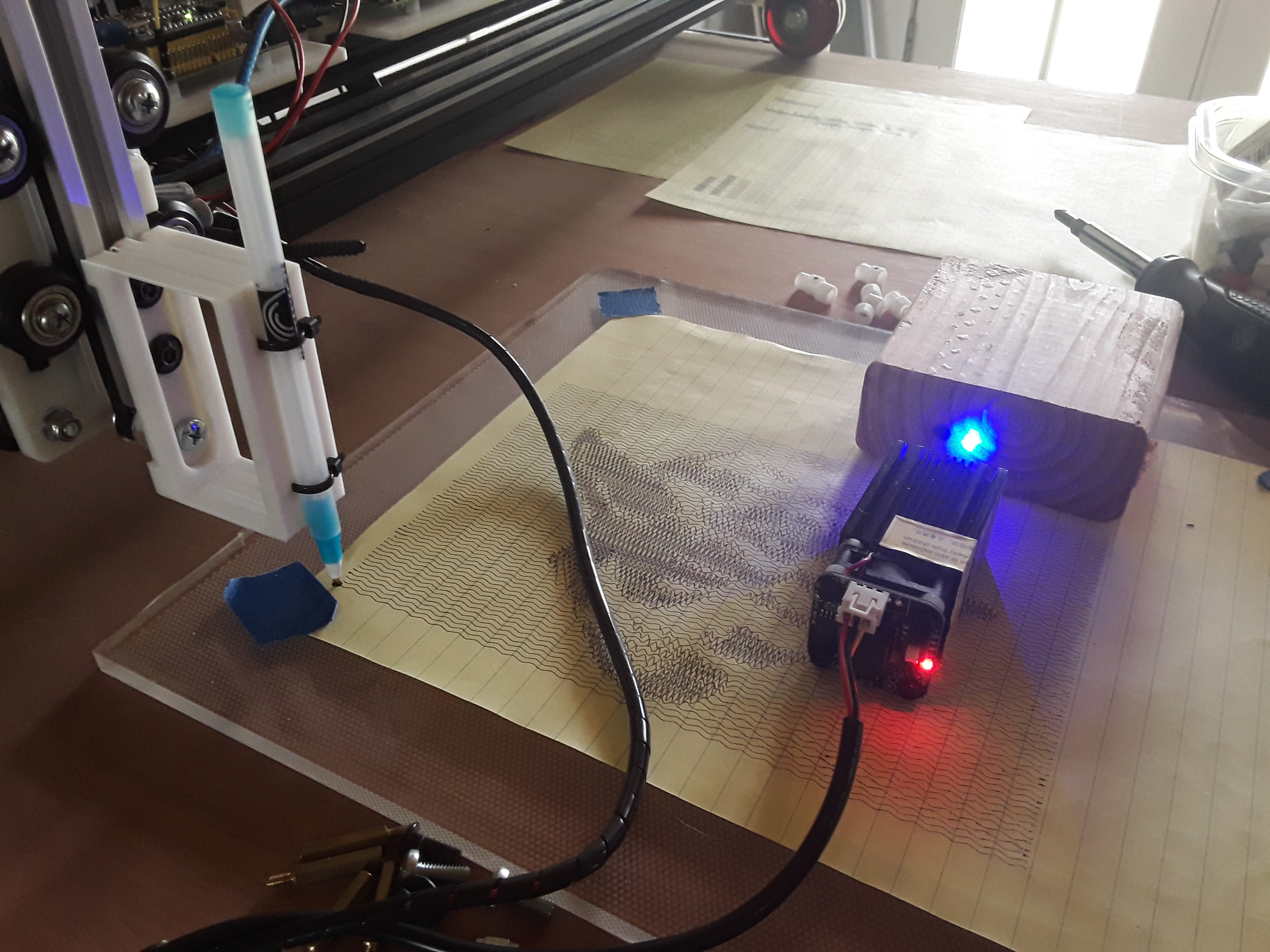
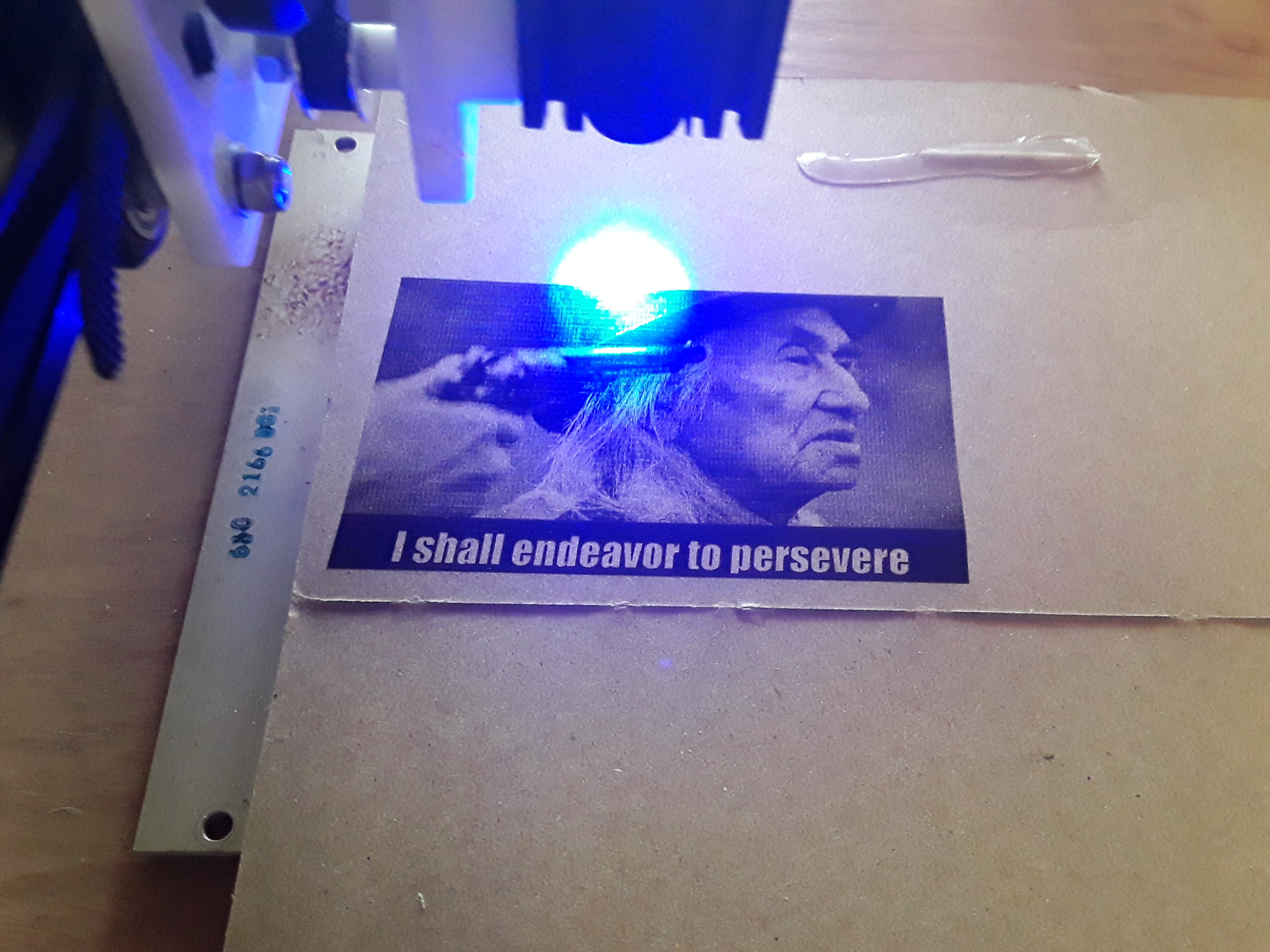
The easy way out, of course, is to simply sit at end of the table (or turn the machine 90*) and swap the X and Y axes. Given the short door cut-off serving as the work surface, it would look perfectly normal using it that way. There’d be less mass moving on horizontally-scanned images that way as well… though my FoamRipper doesn’t seem to have the issue, with an even bigger, heavier gantry, and did the Chief Dan George image I used for comparison.

So I’ll turn the machine 90* and swap the X and Y axes, temporarily. But I’m really at a loss as to why I’m seeing this now… and never before, in the some several laser machines I’ve built in the past???

Any ideas? Jeff? Jamie? All you other “brains” out there… not wrapped up in all the Primo hoopla? :roll_eyes:

And, yes… I did check all the grub screws :wink:

– David

1 Like

An interesting problem. I might suggest putting a mark on one of the wheels and doing a time lapse to see if the wheel is slipping a tiny bit each traversal or if its a software roundoff error like you hypothesized.

I am guessing not software since this would be a problem even with a toothed axis like LR2. Since both wheels are driven, a tiny discrepancy between the two wheels (for example unequal diameter) could in theory produce a small strain between them.

It’s a major change to drive only one wheel and let the other free-wheel, but maybe as a temporary test you could lift one off the surface and let it ride on a little skate or something so effectively only one wheel is driven.

I’m watching this topic with interest because I’m imagining an outdoor battery powered robot that could cover a whole parking lot with sidewalk chalk…

1 Like

You found the bug I programmed in there. Not really, that is an odd problem. I bought a bag of #84 (3.5"x1/2") rubber bands from Staples today which look like they fit well between the wheels. They were only $3.78 for a 1/4lb bag. You might want to try those if you can find them locally. #94 (3.5"x3/4") would probably be better, but not as easily found. We have some friends visiting for a day, so might not be able to test them until Friday. You might also try doing a series of parallel drawn lines like an 1/8" apart or whatever spacing seems good to you & see if or when the spacing changes.

1 Like

So, the wheels are driving one way, and back, and each time, they slide a small amount only to one side?

The error is proportional to the number of times you’ve moved back and forth on the wheels…

Tires have some very funny properties, and they are far from perfect. Maybe they are sliding, on a very small scale, all the time. And then a relatively very small force is applied in only one direction, and it accumulates because this error is accumulated over the 20m you are driving when you scan across the wheeled axis.

Do the wheels have an asymmetric geometry? Is the table tilted to one side?

I think it is smart to try to reduce the back and forth on the tires. I have spent a lot of time trying to get consistent output on big robots (big trucks) and one thing I learned is that tires are not gears. The kind of errors I’ve seen on wheel grip are pretty interesting when you look carefully. Whatever error you have, it is consistently proportional to the distance traveled on the wheels. So just don’t drive as far on them :).

1 Like

Exactly. I created a file with 7 filled boxes… differing only with the interval between fill lines.

It’s a bit hard to see in the above photo but there’s a very light bounding box around each filled block… and the severity of the skew is entirely dependent on the number of times the tractors have to move back and forth to draw the fill lines. As you said, “… proportional to the number of times you’ve moved back and forth”…

So, the larger the interval between lines the less the error.

I guess my problem with this is… why haven’t I seen this same phenomenon on FoamRIpper? My theory now is that maybe I would have seen it if the ends of the belt wasn’t anchored… as with LR2 and FoamRipper. Here, with the rolling gantry, nothing is anchored in the direction it rolls… so the drift takes place unimpeded and accumulates proportionate with the number of time the tractors roll back and forth.

I suspect that doing raster scans is worst case for an “unanchored” axis… so it probably makes sense to simply make sure that any repetitive back and forth motion is accomplished with an axis anchored at both ends. I doubt that any appreciable amount of error will build up doing most vector engravings.

I really don’t think there’s any traction problems here… the laser certainly doesn’t represent any kind of a load requiring traction to overcome and my feeds/speeds are reasonable. And the wheels are commercial roller-blade wheels and as uniform as manufacturing tolerances allow… I can live with that, knowing that nothing is perfect. Maybe my table isn’t as level as it might be… yada, yada, yada.

So, I’ve already swapped the X and Y axes and “flipped” my thinking when I address the machine. And I’m thinking Jeff’s words ring wise, “… it is smart to try to reduce the back and forth on the tires.”

Am I giving up too easy? Am I not “persevering”? Anyone see glaring flaws in this logic?

Thanks to all of you for your inputs. I’m still open to your thoughts…

– David

Do you think the rubber bands around both wheels would help at all? This will give a lot more surface area touching the ground if they stay in place. This will become less like a wheel & more like a tank track. Someone had mentioned using rubber bands before on my build thread, but think they were referring to putting separate rubber bands around each wheel. I will probably add more than 1 of these #84 rubber bands to each side, but here is a photo of the idea. I would like to have wider rubber bands, but this is as wide as I could find locally. These 1/2" wide rubber bands become about 3/8" wide after stretching them this far.
IMG_0110_640x480

Hey, Dave! I must admit I have my doubts that those rubber bands will help. It’ll depends on how well “fitted” they are to the wheel(s) and whether there’s any “slippage” between them when under load. It seems quite possible/likely that any loose material or debris that lands on the lower section of the band stretched between the wheels could easily find its way between the wheels and tire/band and jam or throw the machine off track.

I think the fundamental difference in our machines is in how we plan to use them. Where it appears you’re looking for a portable, unconstrained, “free-roller” that will operate on a variety of surfaces with an acceptable level of precision for the task at hand… I’ve gravitated toward looking at it as an alternative gantry on a relatively smooth worksurface, constrained in all dimensions but one, and giving a level of precision on par with the gantry it “replaces”. Where I can get away with “knife edged” wheels and just enough traction to handle extremely light loads like a pen or laser… you need wheels for the worst surface you plan to ever run your machine on and adequate traction to possibly push a stylus/wiper through sand or other material. My machine is not at all suitable for Jamie’s vision of an “outdoor battery-powered robot that could cover a whole parking lot with sidewalk chalk”… possibly the machine you envision is.

Maybe I’m misunderstanding (quite possible!) but it sounds like your machine’s use case is something akin to much smaller version of Ivan Miranda’s sand drawing machine. If so, you might find his machine’s tractor and tank tread designs interesting and informative. He’s a fun guy and does some fascinating stuff!

– David

It is actually amazing how small and consistent it is. The slope on the side of the square is almost exactly a straight line.

I am curious to know if it is proportional to the number of times it changes directions, or the distance it travels. Maybe another square that is twice as wide would tell us.

I’m interested in quantifying it too. I’m guessing from the images that the square is supposed to be 17.5mm wide, and the 0.05mm is the distance between the lines. So it was on for 350*17.5mm or 6,125mm. It had to travel back too though. So it also traveled 6,125mm the other way, but it ended up moving short of that by 2mm or so.

So did it travel 6,125mm and then back 6,127mm back? That is 0.00032x less than it should have. That is tiny.

Or did it lose 0.006mm per turn around (but only in one direction)? That is also tiny.

I keep thinking this is a heebie jeebie effect. Something like the wheels are not really like a gear on a track, but more like spider man crossing skyscrapers at the microscopic scale. And in one direction, there is something that is making it travel 0.9997 instead of 1.0000.

As for what I think of you for giving up… I am totally convinced that is the rational thing to do. Any more experiments involving this are in the effort of satisfying curiosity and for the sake of science. If you don’t get excited trying to figure it out, then you can definitely walk away, working machine in hand.

2 Likes

Thanks, Jeff, for your thougnts on this. And, I really need to credit Oz, author of the Lightburn software, with coming up with the idea behind this test. I find this all very curious and interesting… but I’m totally ill-equipped to handle the “rigor” required to take it much further. That’s why I called on you guys…

In those photos, I used a “bidirectional” scan and the scan lines run horizontally across the block’s narrow dimension… and in line with the rolling of the tractors. The interval is indeed the distance between lines… ranging from 0.05mm (508 lines/inch) to 0.35mm (~72.6 lines/inch). I didn’t really think about setting precise dimensions on the blocks (I “lifted” and altered a few blocks from an engravering power scale project file) and these measure about 18mm x 27mm (0.7" x 1.07"). So, on the 0.05 interval block, there should be about 540 lines… with half of them going in each direction.

I, too, was amazed at the consistency of the error… and really don’t see anything too “heebie jeebie”(?) or random about it. In fact, it makes me wonder if it can be measured and compensated for in some way… maybe with a setting in Grbl (which is what I am using here). I’m sure “somebody” is equipped to figure out a way to measure and set a value to put into Grbl to do that compensation… but it certainly isn’t me. And it’s probably only necessary for odd machines with a “free rolling” (un-anchored) axis.

Now, after talking with you guys, I know that I can walk away with a machine that does a reasonable job of carrying around a pen or laser, and is capable of turning out stuff that at least looks good to the eye. And I can be “satisfied” I did all I could reasonably do… I just didn’t want to miss something obvious.

Thanks, again!

– David

So, some of my estimates were off by a little, but it is still the right order of magnitude. Somewhere in the few hundreths of a percent.

Any compensation would have to accumulate the error as the distance traveled on the wheels, and not some XY position. Marlin has skew correction, but it is based on consistently being out of square. So that wouldn’t help, or else the outside edge you drew would then be “fixed” by the skew, and would then be the crooked part. It would definitely be some custom math. Something like having a global variable for compensation, and you would have to constantly add a number proportional to the distance traveled to it, and it would have to add up to enough correction to keep the box square, and then there would be very little incremental adjustment for the bounding box around the edge.

By Heebie Jeebie, I just meant that it was on a scale that my normal newtonian physics seems to break down. I can’t explain why it would be so consistently biased in one direction with the simple models from physics 1. I’m not saying it’s quantum or relativity involved, just that there is something going on, and it doesn’t seem to me to be explainable by the simplest friction model.

I do wonder if the angle would change if you tipped one end of the board up by a few inches. But that’s me thinking that it is summing the force over time whenever it is moving, and it not being level is making it consistently go in one direction.

It’s interesting to think about anyway. I’m certainly not willing to do the test myself. :man_shrugging:

2 Likes

It’s been a while since I used Lightburn, but if I recall, it has an “overshoot” capability when running a raster image. Any chance you’ve got a negative value in there somewhere, causing each line to get a bit shorter as the “undershoot” gets added (subtracted?) from the previous line’s length?

1 Like

I’m modifying my Lightburn file right now and will produce gcode… to do a couple of boxes, same 0.05 interval, but one twice as wide as the other. I was thinking 1" x 1" and 1" x 2" for the boxes.

And I, too, wondered the effect if I simply blocked up one end of my table to run the test. That would be really simple to do…

I agree once you start talking about micron scale, a whole universe opens up.

A soft wheel rolling on a hard surface can behave like a wheel with a slightly smaller radius.
image
Suppose the green circle represents the diameter at which the translation exactly matches the rotation. Then you can also have a phenomenon where little parts of the contact area are slipping one way or another (yellow arrows) due to the difference in radius while you have uniform translation and rotation.

I don’t think this is happening but the point is that things get weird when you look closely enough.

Another possibility which I think is a bit more plausible is if the belt tension is changing, then it could cause very slight relative rotation between the two wheels on a very tiny scale:
image
If the weight distribution is shifting due to acceleration then one wheel might slip more than the other in a systematic way and very tiny differences could accumulate. This is where driving only one wheel could make a difference. It’s just a theory, and hard to say how likely it is to be a contributor.

2 Likes

Thanks, Tom. I checked and the “overscan” iis turned off.

BTW I’m using cut definitions in LB called “Fill+Line” for these blocks… but it does have “overscan” functionality (if turned on) and “line interval” settings just like an “Image” cut definition. So, technically, I guess there’s no real difference since the laser doesn’t know if it’s tracing a “fill” line or a “scan” line.

I wonder if there is something like one wheel is slipping (very slightly) , and when it’s the back wheel (w.r.t. Direction of motion) it has slightly more downward force, so the front wheel slips, and since the two wheels are slightly different diameters, they get a different steps/mm going forward and backward.