Hello all,
I’m beginning my CNC journey by building the Lowrider v2. Over the past few months I’ve printed all the parts as time allows and I finally bit the bullet and ordered the hardware from V1.
My build is going to be a little different than some, but should be pretty vanilla in a lot of ways. I hope to keep this thread organized with my progress and document some of the pitfalls I’ve worked through.
Ryan was sold out of the SKR 1.2 when I wanted to order, so I sourced mine from Amazon and along with a TFT35 v3.0. First mistake right there, I didn’t realize that there is both a TFT35 v3.0 e3 and a non-e3 version. There isn’t much difference between the two, just the location of the control knob. It did mean that I needed to source a new case for the controller.
I used this for the case for the SKR Pro 1.2:
but that only works with the TFT35 v3.0 e3. I found a case for the TFT35 v3.0:
and remixed it to match the mounting holes for the SKR’s case as well as to use 3mm hardware.
With that all sorted I started in on some other organization. I designed a holder for the AC adapter that V1 sent:
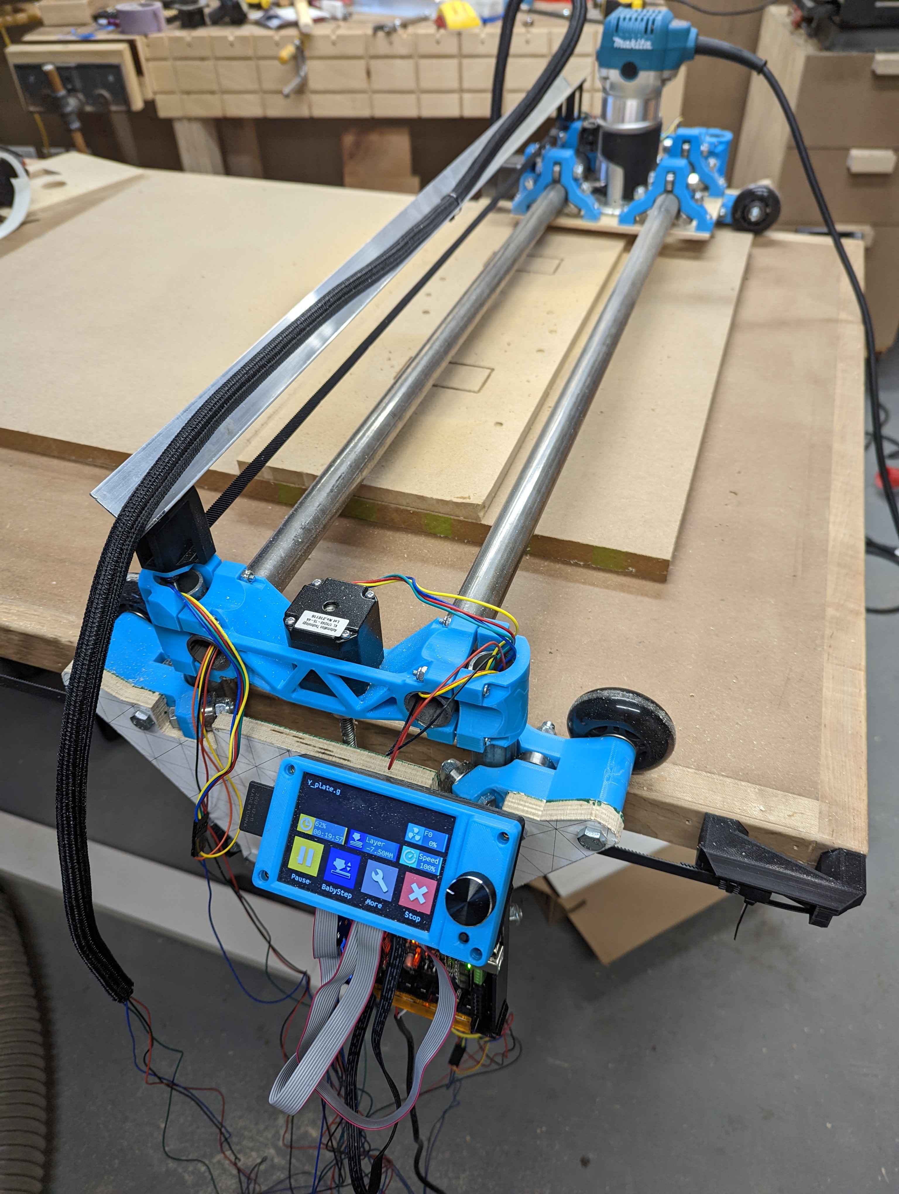
I plan to mount that on one of the Y plates along with the control board and TFT.
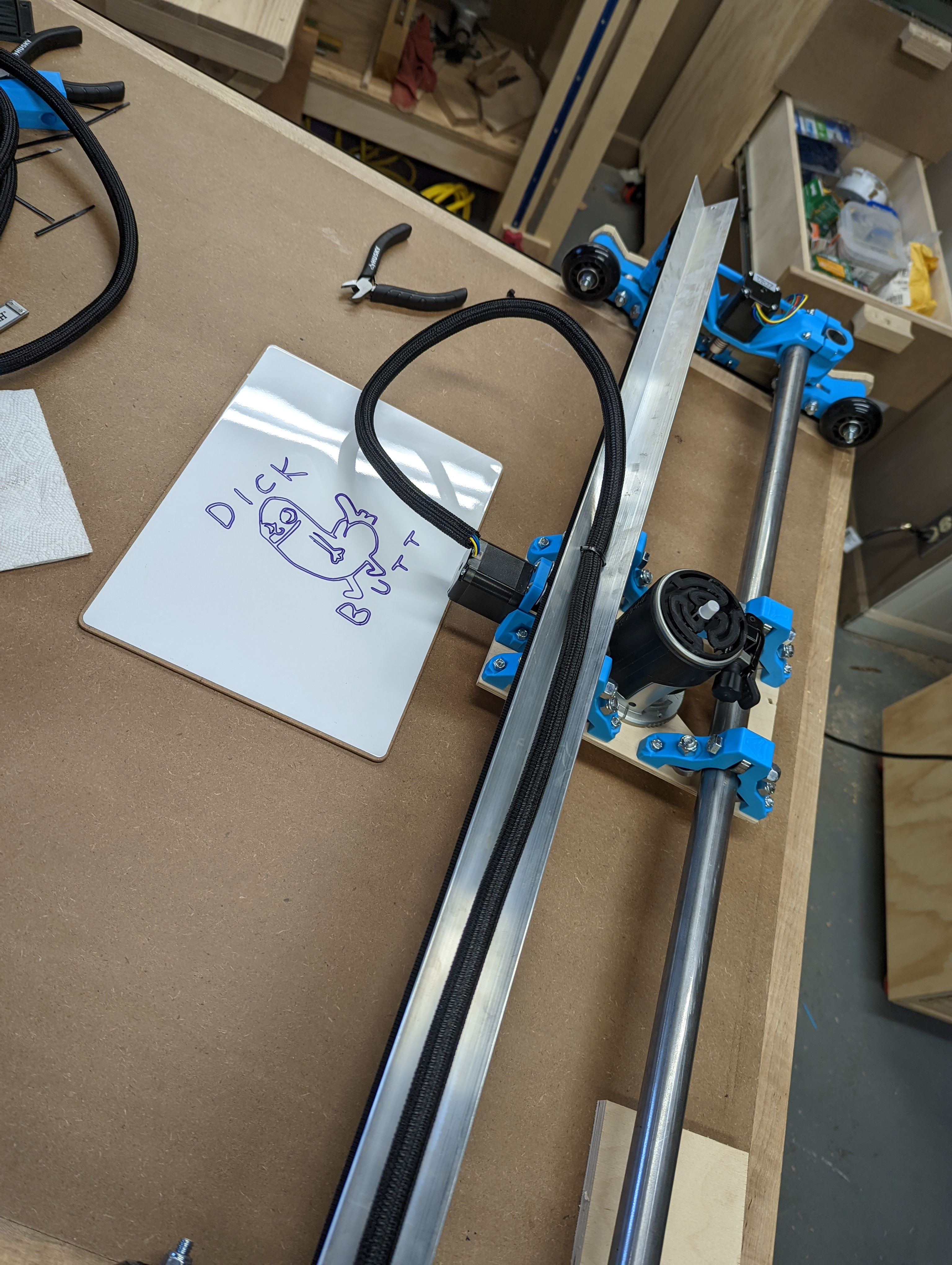
Got the whole thing assembled and sitting on my workbench now. Still have to make a new table top for it and connect all the belts.
Hope my SKR case works for you! Build is on the right track by going vanilla and then modifying to your needs. If your table is tried-and-true (literally) you’ll but cutting in no time.
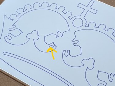
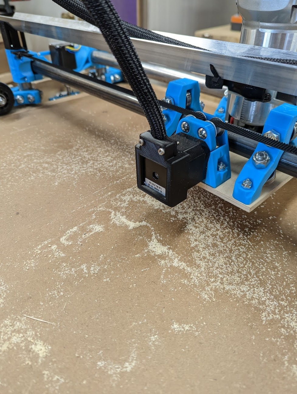
That could just be flex in the pen, depending on how rigid the pen mount was. Given that it looks the same on both “closings” I don’t think it was the workpiece moving.
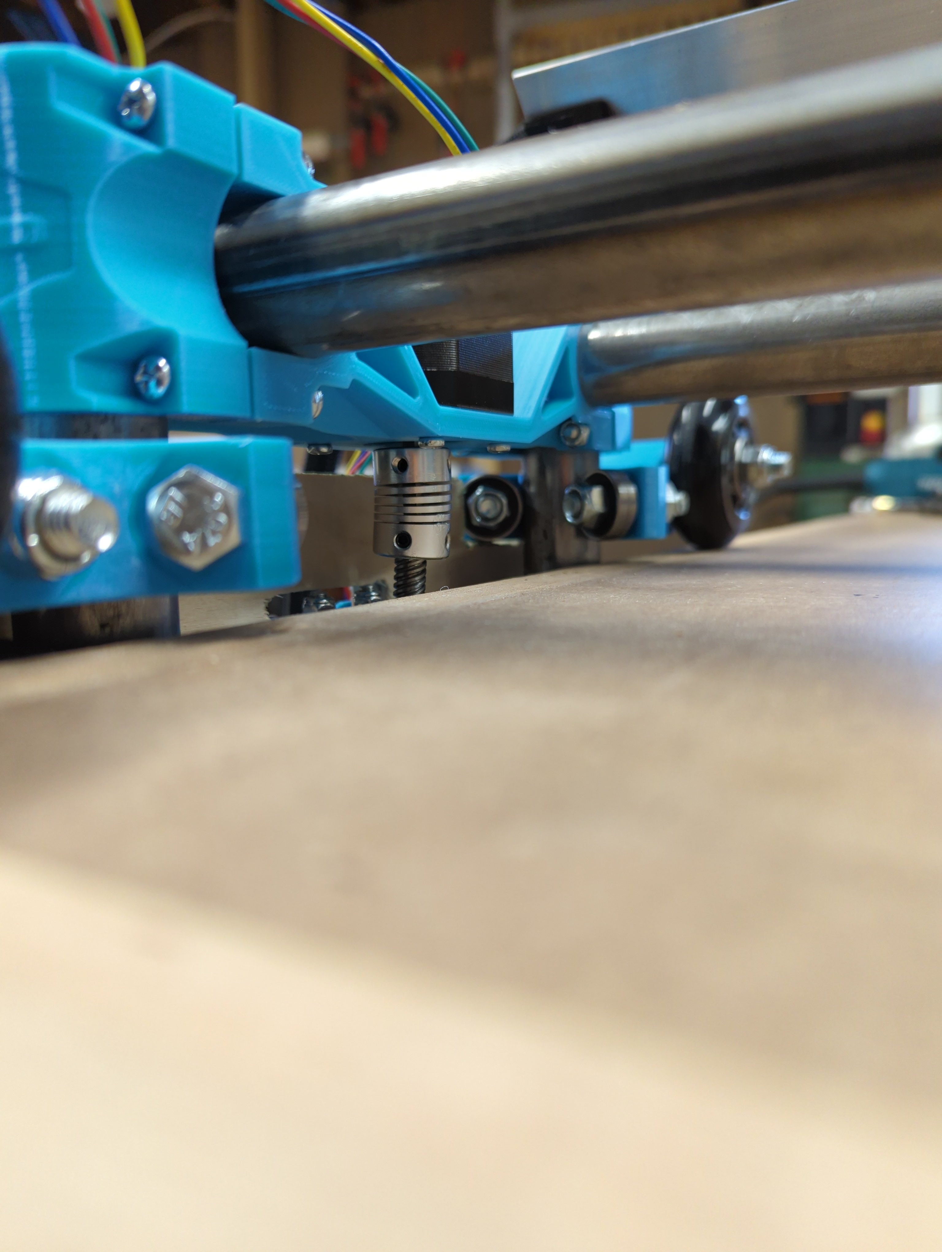
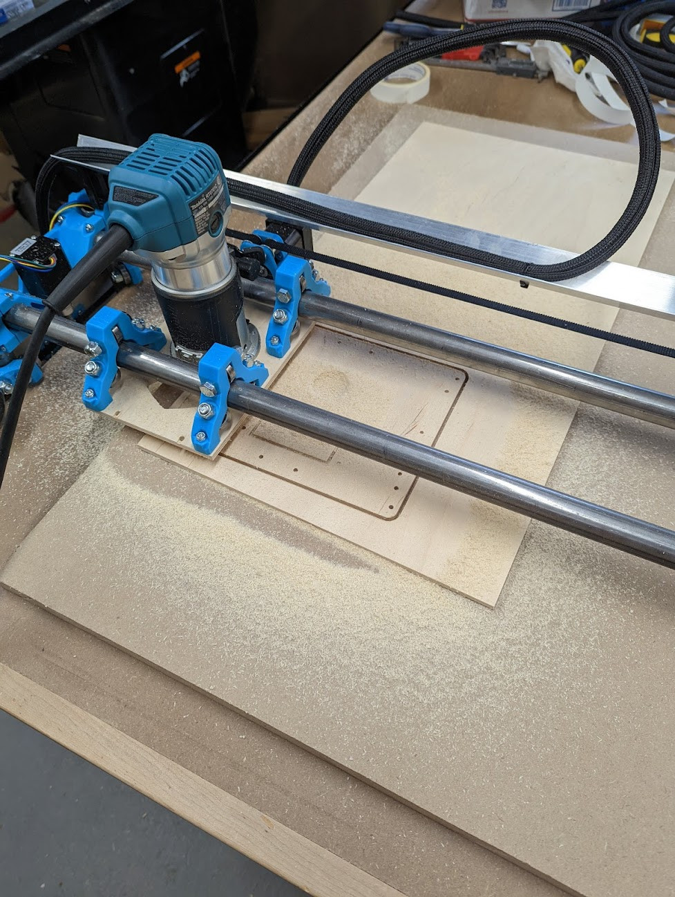
Problem 2 that my z couplers are really cocked when the gantry is fully lowered. It seems to work fine, but I don’t want to be blowing through couplers
EDIT: I just re-read and took a closer look at your picture, as I understand now, the problem is not your coupler being “extended”, but rather the fact that the motor shaft is significantly mis-aligned with the leadscrew holder on the Y axis.
The problem is more visible when the gantry is lowered because the angle they form goes up
It seems that your XY center piece is reversed (see https://www.v1engineering.com/wp-content/uploads/2018/07/00100dPORTRAIT_00100_BURST20180719181652856_COVER.jpg, the “closed” side faces the table, and motor is on the outside ). I think that’s the root of your problem
###########
Original post:
The Z coupler should only be “extended” by the lead screw if you’re trying to lower the gantry when it’s already at minimum
That’s not the case in your picture, which is strange…
Is anything binding, preventing the gantry from going down? Or is it just that the coupler already suffered from extension in a previous episode?
In any case, here’s the link to a “coupler saver” that might help with the first “oopsies”
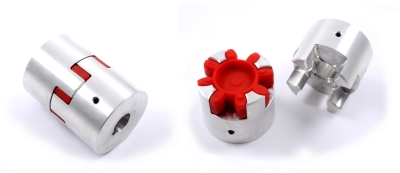
I also found that using “spider-style” couplers make this problem disappear
The two parts just disengage if you lower the gantry too much…
Also it’s usefull if you want to be able to quickly disassemble the Y plates from the gantry (eg. for storage) as long as you can disconnect the wires…
I think Ryan’s recommanded against using this kind of couplers though, can’t remember why…
Something seems to block the Z from going down, indeed!
I believe you should try and loosen the leadscrews, lower the Z axis completely and mount them again.
Somewhere in the FAQ there was a mentioning that you should stretch the coupler a bit. TBH I didn´t do this, the leadscrew and stepper-shaft just touch, so the coupler isn´t stretched (but in that way that you can not compress it neither!). I have no issues with this. To be correct; I already tried to lowed to Z further then it can go, so I overstretched the couplers many times now without any issue. The couplers are still in great shape.
I would be afraid though that those solid couplers might do more harm in such situation.
The red part is a bit “gummy” and will allow a bit of flex
The two aluminium parts are just fitted one in another without anything else holding them together, so if your gantry is set to the minimum (or stuck against your workpiece) and you try to lower it, the lead screw will just pull the coupler appart, separating both halves and disengaging the gantry
I personnaly see this as an improvement, as the gantry will never be “pulled” by the lead screw
When going up, the lead screw’s end will push against the motor’s shaft, but going down, the gantry will just slide down under it own weight, the lead screw just acts as a “moving endstop” and won’t “pull” the gantry down
The cutting tool won’t be “forced” into the workpiece by anything else then the weight of the gantry (and that’s already quite some force)
On the other hand, if one sees the leadscrew “pulling down” the gantry as a benefit (eg. for drinving the tool straight down hard into the workpiece), the “classic” couplers won’t do either (they will only stretch and break)
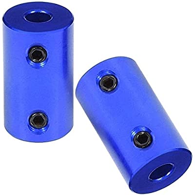
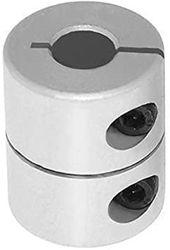
The couplers I think should be absolutely avoided are these solid ones:
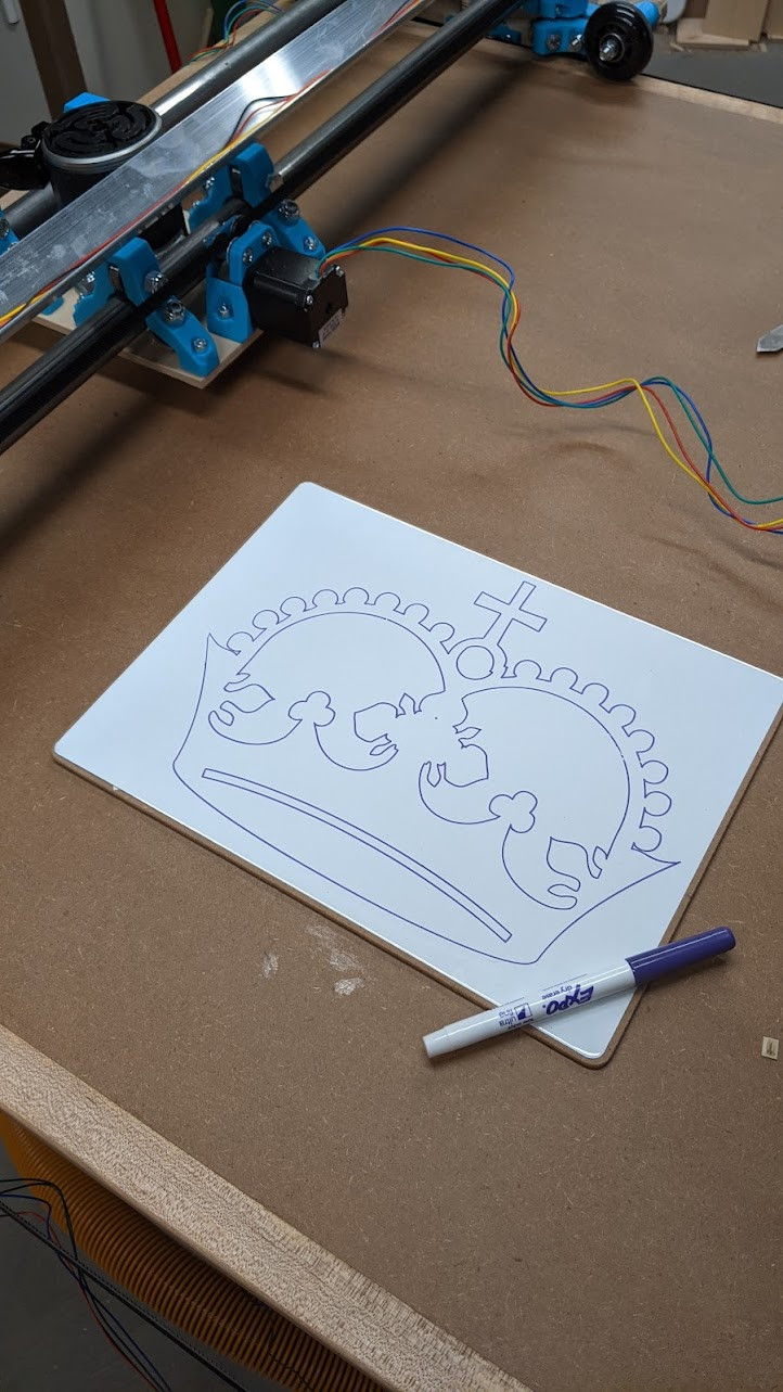
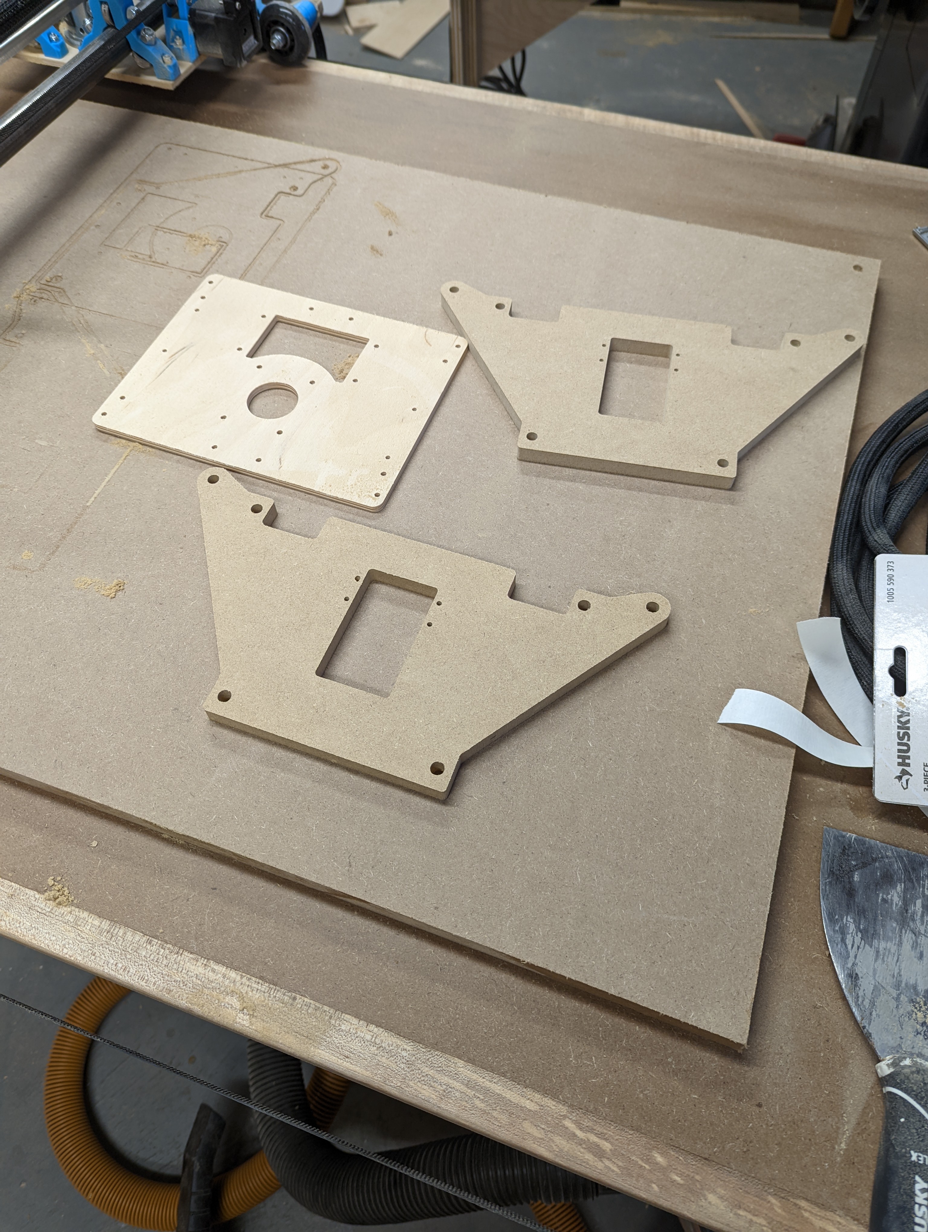
Since I need to flip the XZ mains (which means I need to disassemble practically everything) I decided to recut the flat parts since I have a working CNC.
Cut out some new flat parts since I need to fix the xz mains, rattle canned them flat black. Got a JST and Dupont crimp kit coming and then I’ll do some hardcore cable management on the rebuild.
99% satisfied so far, but did have one failed cut:
You can use it all you want just run jobs from the marlin side until we figure out what is wrong with the tft. It only takes 3 seconds to switch sides.

