Rethinking or overthinking?
I’m not about to embark on building this yet, as I want to get the “as designed” setup working so I have a base to experiment with, and please note that I have ZERO machining experience, so I am posting this for DISCUSSION purposes - to toss around a few ideas.
WHY?
The Lowrider Plate was developed for the DeWalt, and the modifications to suit the Makita installation that I’ve seen to date are mostly adaptations of that, however the router is quite different in detail, and I have a few thoughts about how the separation of vacuum and cooling air can be improved.
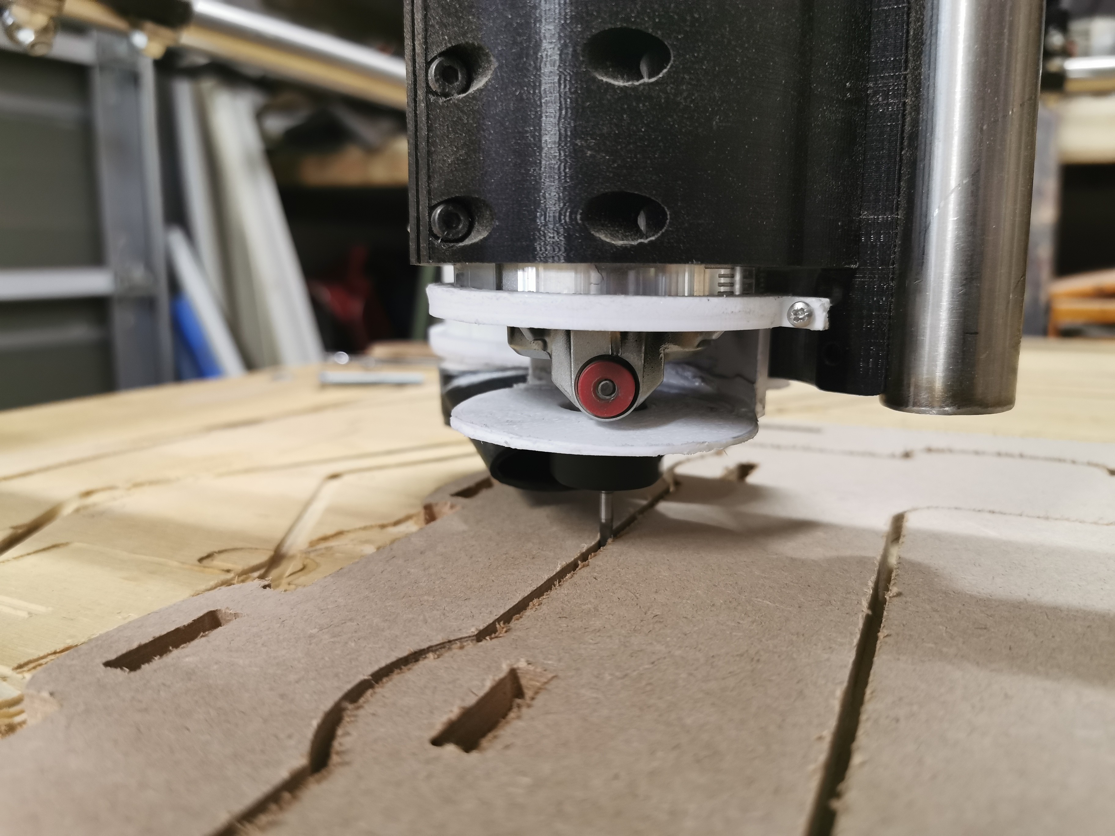
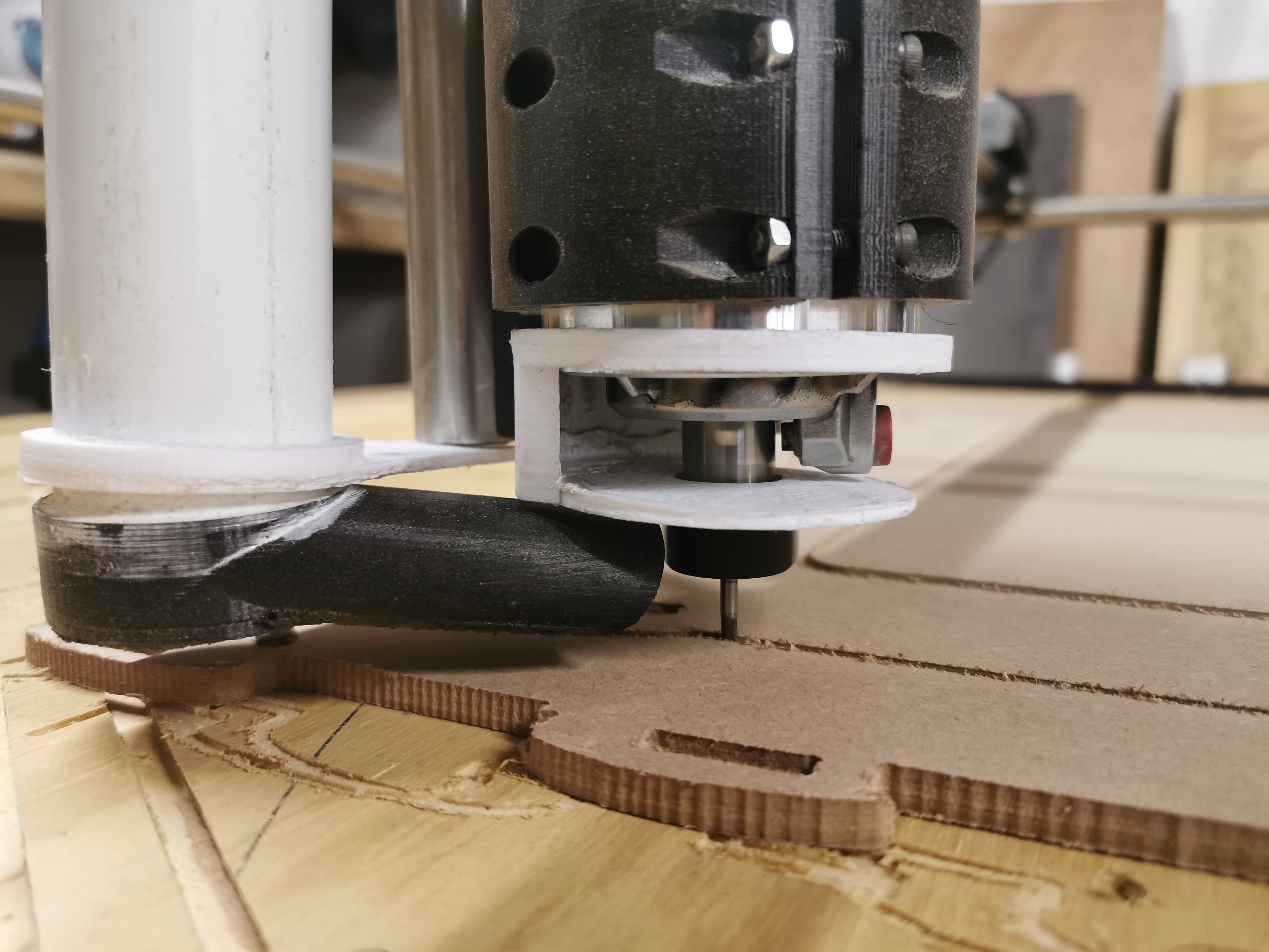
I actually love the way @vicious1 has designed the vac parts - every bit about them is neat from an industrial design point of view, but I am not sure that the dust collection and mount has been developed quite as far as the other components. “Not sure” means exactly that. I have a lot of experience installing and using dust collection around may place and the only real worry I have with the LR2 is how much dust it’s going to create, and how little control I’m going to have over that.
As a bonus, with no experience tramming router mounts, but a lot of experience levelling tripods, I KNOW that three feet are better than four for that job, so levelling the new base should be a doddle.
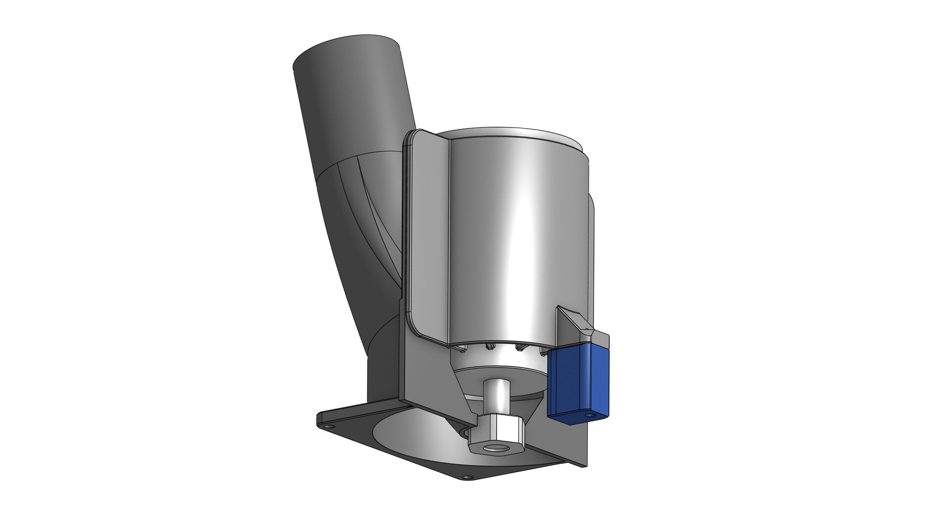
Oh, and after Dan’s @SupraGuy comments the router body mounts so that the collet is always just above the base plate - maximising working depth of the bit. Just drop it down onto the lip and it should be simply and repeatably at the same level every time.
This design is a very rough preliminary sketch, without regard to structure and so on - but I am fairly sure I can make it work - I’d like to develop the levelling base a bit further too so that it can be levelled using three screws from above.
Ahh… yes… the bid square knob on the top of the router is missing, so the router is a few inches shorter than reality.
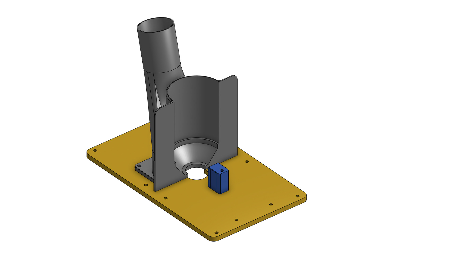
Here we go:-
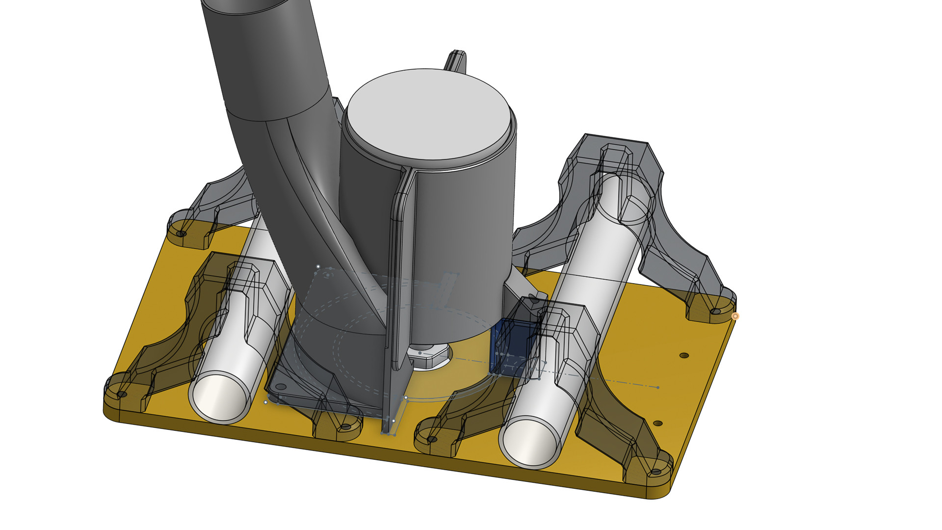
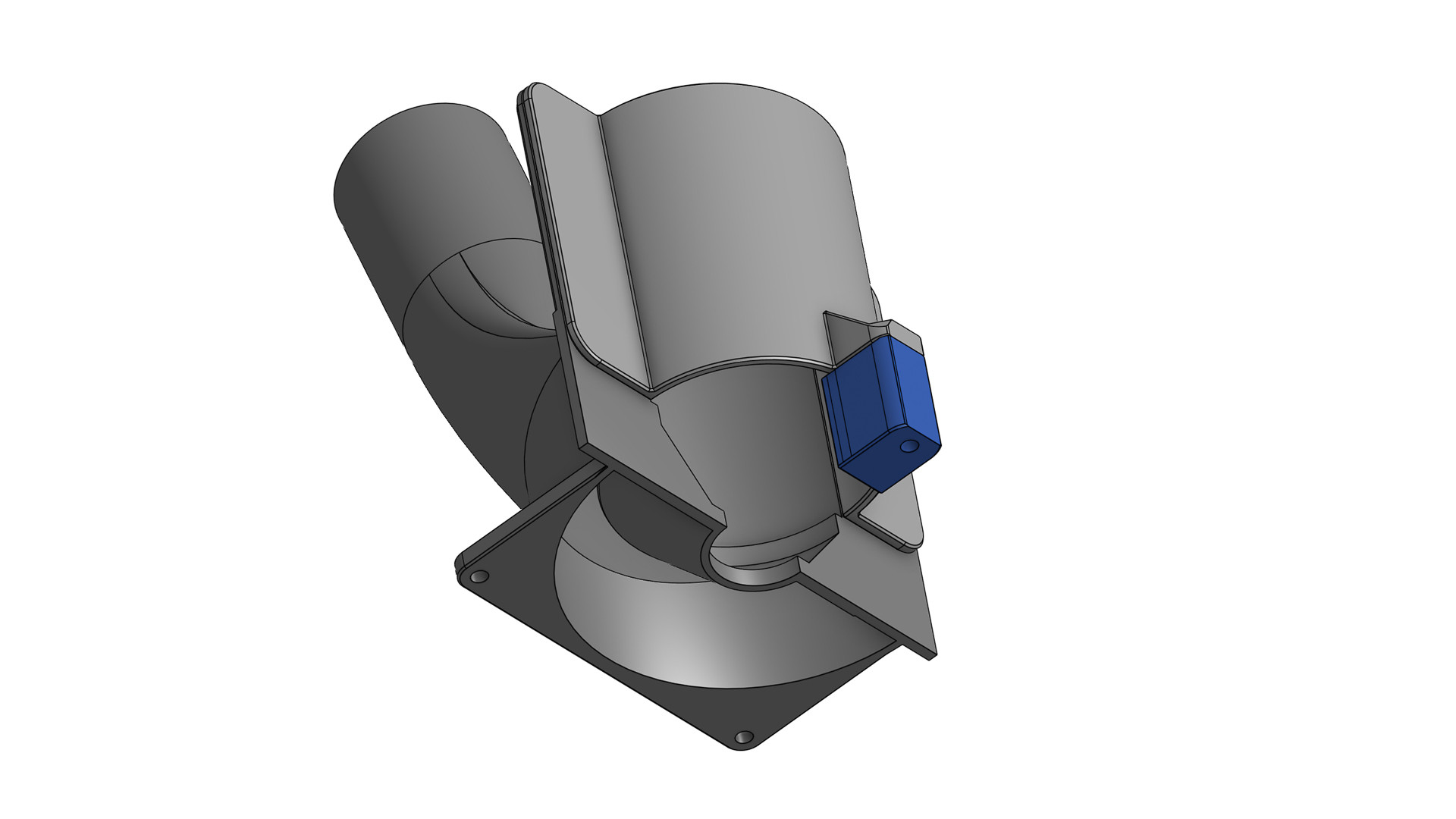
This is inspired by a couple of MPCNC solutions I’ve seen; hopefully by moving the vacuum attachment closer and avoiding that narrow dog-leg under the tube, we’ll end up with more suck! The vacuum connection and “back half” of the mount are one piece and will print without support. The "front half will also print upright and the little mounting piece (blue) won’t be a problem either. The two halves will be bolted - permanently on one side - knurled knob on the other or a quick release.
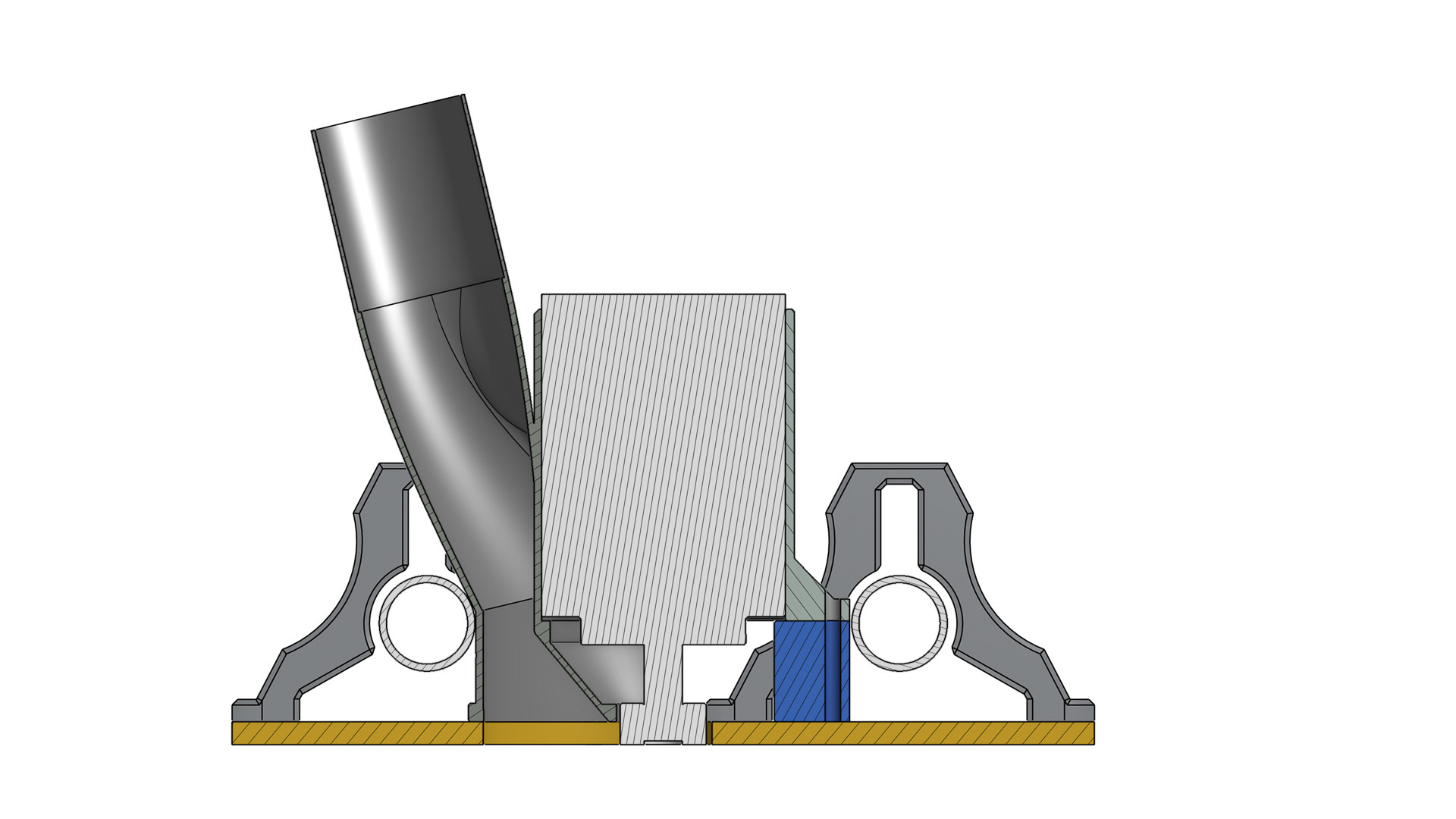

The section attempts to show the separation of air flow, and as a bonus the exhaust cooling air will be directed towards the x stepper. New Base shows the simplicity of the connection.
So my question is: Should I develop this further, or will I be wasting my time?
I am genuinely happy to be shot down in flames here - and as I have said before feel a little awkward because I haven’t done any testing first, but it filled in a day that I would have been far better employed doing other things!
Cheers and thanks!