I have a hard time answering laser questions. It seems like every answer is, “it depends”. Pin 45 doesn’t do anything out of the box. Ryan is getting the laser stuff in the next few versions of firmware. If the pwm is 12V tolerant, you can probably use the fan output and M106/M107. Otherwise, you’d need to set the laser pin to 45 and turn it on in the firmware to use pin 45 (which is 5V).
1 Like
The nightly builds of our firmware have the laser enabled on the Rambo if you want to try it out.
I’m alright with trying the fan pin. My next dilemma is the laser only has a single red wire that’s not already plugged in to something. It’s just like the picture shows on the far right. Power connection and little red wire.
The fan pin is 12V be very certain your laser can handle that signal, most can not.
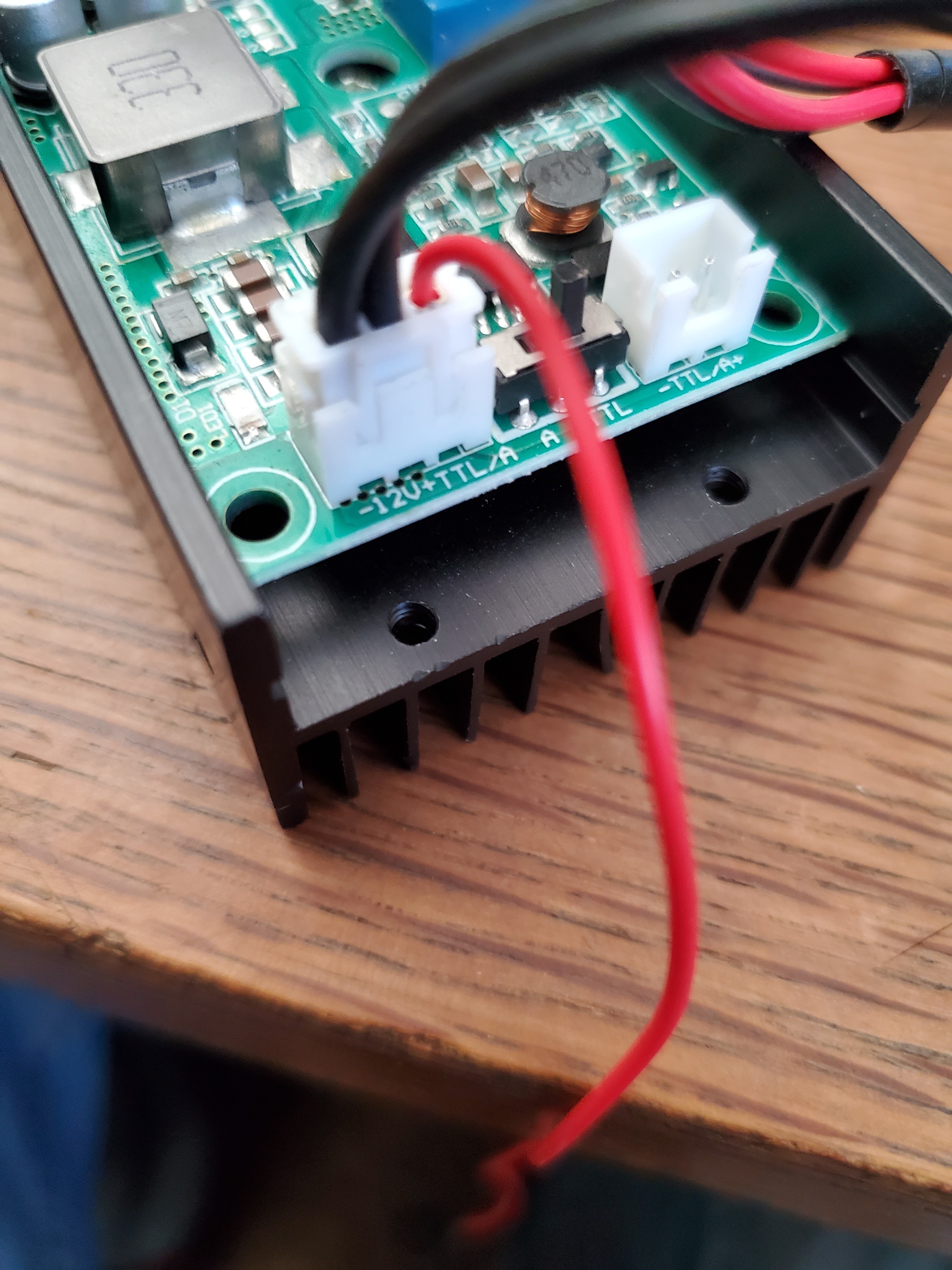
Maybe someone will recognize your laser from this picture, but generally you will need to look at the specs for your laser to determine if it is 12v compliant or not.

No, this laser is 5V TTL. The line you want is this one:
![]()
So you must use a 5V pin. I don’t know what changes Ryan has made lately to support lasers, but historically from this forum, the process would be to redefine a fan pin to a 5V PWM pin, and to use that pin.
In pins_Rambo.h, one of the fan pins would be modified in this section:
#ifndef FAN_PIN
  #define FAN_PIN                              8
#endif
#define FAN1_PIN                               6
#define FAN2_PIN                               2
One of pins 44, 45, and 46 can be used, and they can be found here:
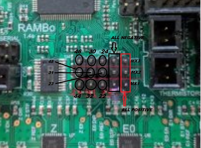
So say you want to use fan2. You would change the #define to:
#define FAN2_PIN 45
Then your laser would plug into the middle pin on the left column of the pins in the picture.
My only experience with firmware is loading it on the board. What program should I use to make the changes. I have a purpose for the p2 fan pins so if I modified fan 1 to #define FAN1_PIN 45 that should do it?
Any text editor can modify the file, or if you are using PlatformIO to compile and upload the firmware, then Microsoft Code is a good choice to modify the file. The file to modify is Marlin/src/pins/Rambo/pins_Rambo.h in in the source files that you have for the Marlin firmware. You might also wait a bit for feedback from @vicious1. It is possible that his recent laser work already has a 5V pin defined and/or he uses some other method besides fan control to control the laser. If so, he can give you a bit more information on how to download the daily build.
And yes, you can use one of the other two fan pin #defines.
He said something about the nightly having it enabled but I’m not entirely sure what that means.
Also! Thanks for all the helpful input!
I’m pretty sure I have successfully changed the firmware. Unfortunately it’s time to go to work. So I will load it on the board in the morning when I get home or something.
The Nightly firmware already has the 5V pin enabled as well as all the M3 options that seem to work best. might want to look through my “Lasers...revisted” thread real quick to get some specs.
I am finally getting back to this laser stuff and I’m trying to make a make the the change to firmware. I changed the #define FAN_PIN and FAN1_PIN to 45 but they both give me the same error in the sanitycheck.h
( #error “SPINDLE_LASER_PWM_PIN conflicts with fan1_pin.” 3107, 8
It says the same thing for both FAN1 & FAN if i swap them
I noticed an update to the firmware is it possible I’m trying to change firmware that has already been updated?
If you are using the latest firmware, then yes it is likely that you have a conflict. You are beyond my understanding of the laser at this point, especially since I don’t have one. I just have a bit of info since I preparing to install one in the near future. You have three choices:
- Assign pin 44 or 46 instead of pin 45 to your FAN_PIN or FAN1_PIN.
- Don’t do anything and figure out how to trigger the SPINDLE_LASER_PWM_PIN in your generated g-code (probably the right long-term choice)
- Reassign the SPINDLE_LASER_PWN_PIN to something other than 45 to remove the conflict (like 46 or 44).
I will attempt option 2
I flashed my board with new firmware, hooked up the laser and at first it was always on. I then had control of it for a moment and now it’s not doing anything
If you take a look at lasers “revisited link” that Ryan provides above, you will see a g-code file associated with the first post. As a test, you could just take the first several dozen lines of g-code from this file and run it on your machine. If you look at the code, it is controlling the laser using the ‘S’ parameter on all the G1 g-code commands. You will see something like this:
G1 X26.22 S52
The ‘S’ parameter with a spindle is used to control the spindle speed. With a laser, it controls the laser output. I believe the values run from 0 for no laser to 255 for the laser on full. So the value of 52 for the ‘S’ parameter should turn the laser on about 1/5 power. I’d be surprised if the laser output is linear, so you likely have to run some tests to figure out laser output for various values.
Since I’ve not yet played with outputting any laser code, I don’t know what needs to happen to get the various post processors to output the ‘S’ parameter in this way, nor how to author the various levels of laser output in the CAD/CAM software.
Note that the laser stuff appeared in the latest version of the V1 firmware, so you still need to flash it to your board.
1 Like