Okay… Now I just need to figure out what plugs in where.
Z_MIN is the touch plate. Got that.
Z_MAX will be the stop for the Z1 motor.
Pretty sure that X_MIN is the X stop, and Y_MIN will be the stop for Y1.
A little fuzzy on where Y2 and Z2 stops plug in.
I thought I had a longer drag chain than I do for the X motor. It’s not a huge problem, for now, but it’ll need addressing.
Crimping wires is a pain in the rear. I have a ratcheting crimper that does a nice job, but I need to finish the crimp with pliers to get the pins into the connectors. I have a non ratcheting crimper that the pins stick in, but gets the crimps tight enough for the connectors. Both are a pain to use in different ways. But I have my wires done now, just have to sort out where they are going, and maybe put some sleeving over some of it to make it look less messy.
Yeah, probably not needed, but I like the auto square, particularly for Z.
Trial and error got me where I needed to be. I guessed that Y_MAX would be Y2 and X_MAX would be Z2, correctly, but wired the switches the wrong way(I had wires poking through the X tubes and had them backwards.)
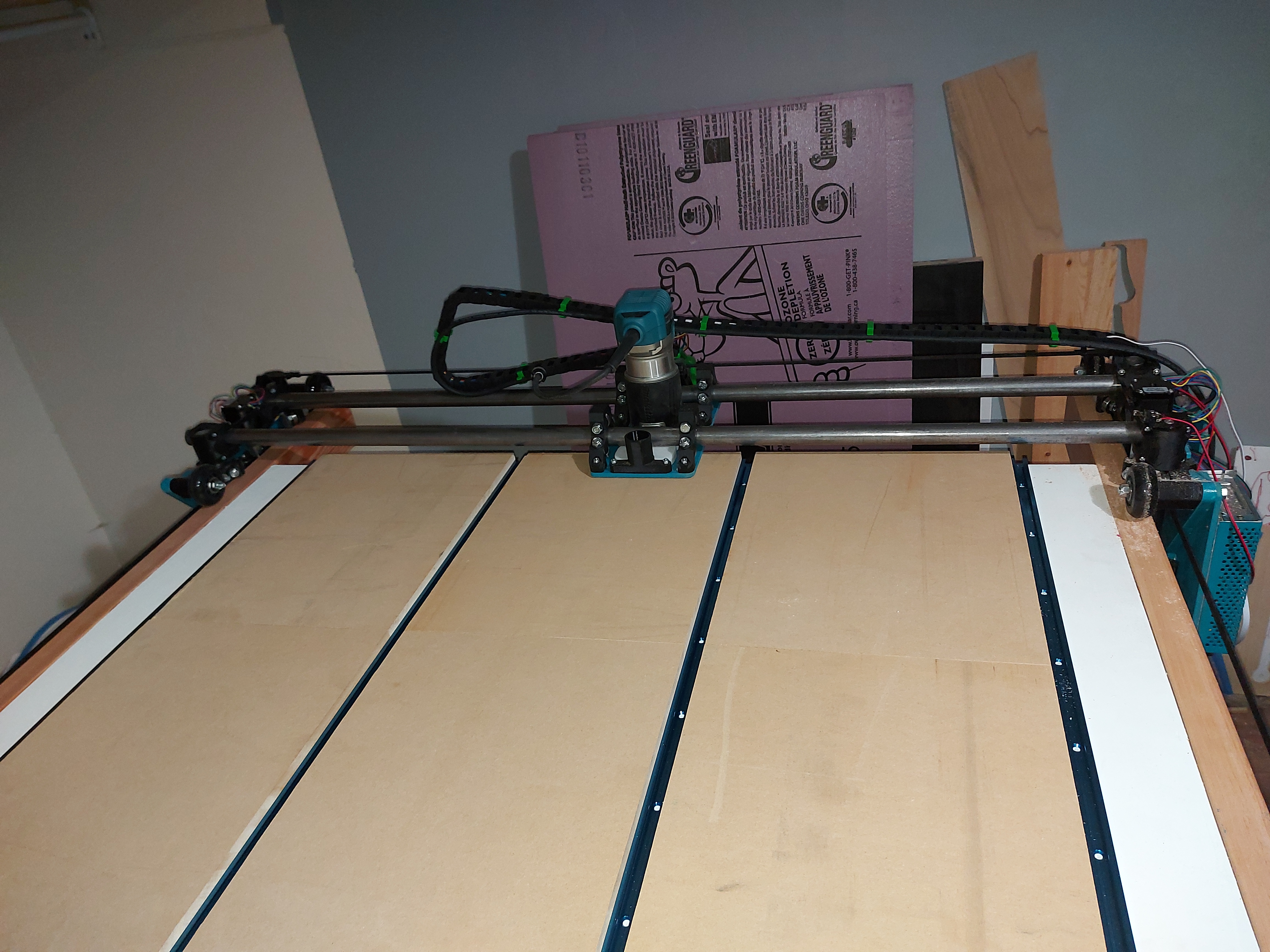
The Y switch bumps are on the printer now, homing X and Z works as expected.
First movement test looks good, I happened to get all the motors plugged in right way around.
I had originally planned on 37" for X, but after adding the rails to the table, I have a 48" wide table, so 40" usable, I think. The rails are 6’ in length, so 57" of Y. A little bigger than planned. Big enough for most things I’ll want. (Full sheet would have been nice though.)
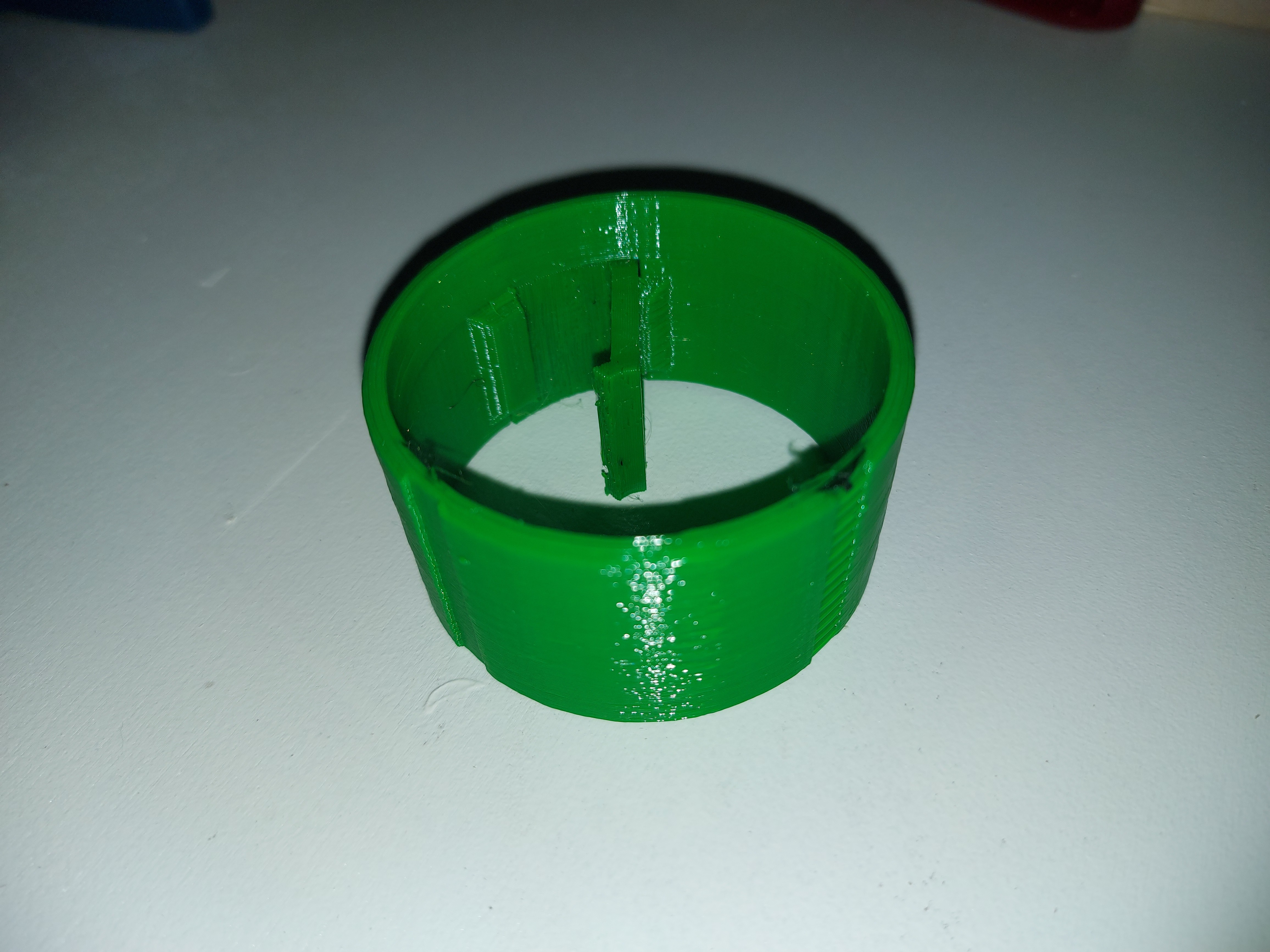
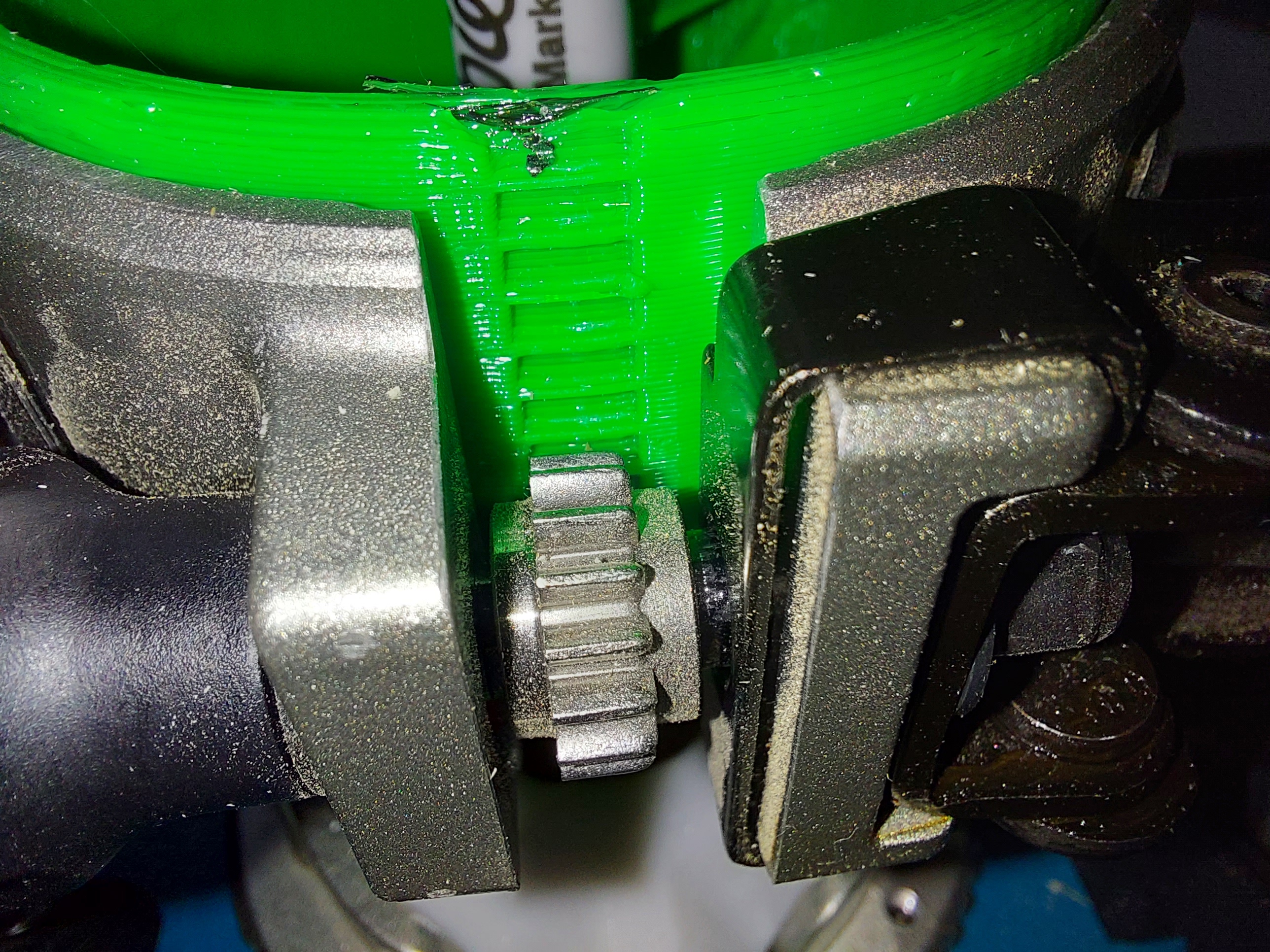
Well, version 1 of my bump stops are crappy. They need revision, but they’re functional enough, and I’ve got it as square as it needs to be.
I’ve got my Z stops square to within what I can see with a tape measure, so less than 1/2mm over a 1m span.
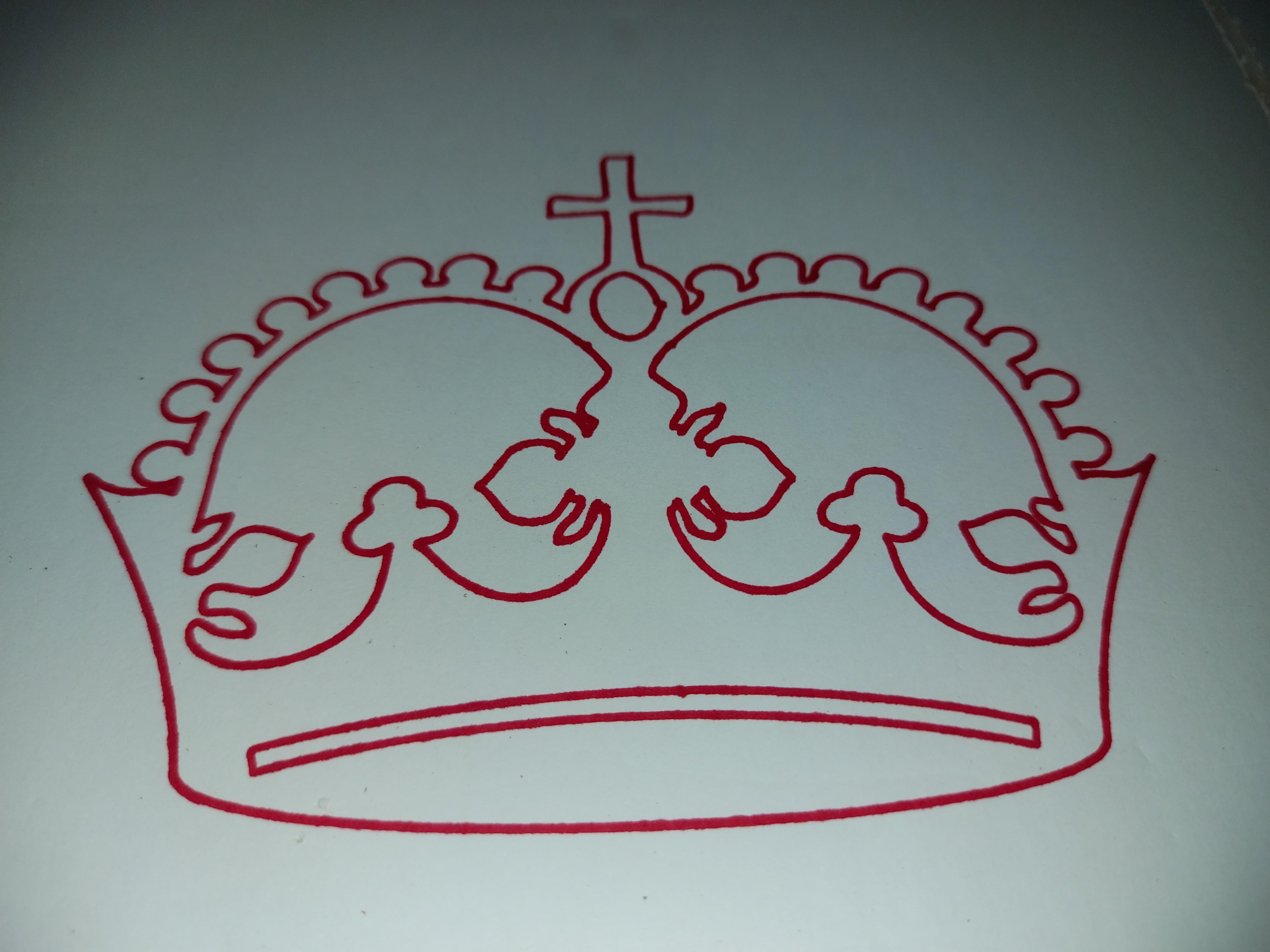
Next step is printing a pen mount to draw the obligatory crown. I’ll be looking on Thingiverse, but anyone have a handy pen mount for a Makita mounting clamp?
Okay, so I just spent far too long chasing the rabbit of a pen holder that will work with the Makita base. While I think I have a solution, I haven’t printed it yet, and it’s getting to be time for bed.
Well, since I’ve used the pen for the Primo only to draw a test crown, I’m not anticipating this being a long-term useful endeavour… but who knows…
So I’ve made a decision for the spoilboard. I’m going to go the slightly more expensive route of using T Track and then just place material between it.
The T track is 3/8" high. I think I’d be fine with a 1/2" high spoilboard, but I noticed today that I need a fairly long router bit to reach down to 1/2" above the table, and about 5/8" is as low as I can go and still be able to reach it with most of my 1/8" mills. I may end up with 3/4" as a default, so that I can be sure. (Though I still have 5/8" material left over from the Primo spoilboard.)
Now the decisions…
I bought a pack of 4 4’ lengths of T track.
My work area is 45" by 60"
I see 3 options for this.
Place 4 pieces along the 60" Y axis, leaving 6" at either end where there is no T track. These would run 14" apart, assuming one at either edge, and 2 equally spaced between. I might need slightly longer clamps, as I think mine are just about 5" but I should be able to use most of the clamp hardware that I already have.
Cut the pieces down to 45" and space them along the 45" X axis. This places then 19" apart. The advantage is that the whole spoilboard gets covered, but the disadvantage is that it’s possible to leave an edge awfully far from anywhere that I can clamp it down. I can probably manage the edges, because it will go edge-to-edge across the X axis, but it could be somewhat distant for some pieces.
Cut 1’ segments from one track and run 3 tracks along the Y axis. This gets back to edge-to-edge, but this leaves the tracks 21 3/8" spaced. This is kind of wide… I thought it would be OK at first, but the actual math makes it undesirable… It also wastes about a foot of T track extrusion.
I think I might have just talked myself into another option. Option 1.5. Leave the last 1’ at the maximum Y with no T track. If I end up needing it at some point, deal with it then by buying another 4’ length and cutting it into 1’ segments to extend all 4 tracks the whole length.
Yeah, I think that this is the approach that I’m going to take. I’ll have to think of some creative ways to make longer hold-down clamps, since I might end up over a foot away from T track for some cases. Both edge T tracks will be outside of the machine’s range, so I should always be able to use them for hold downs, though I can’t go far back from there as it will impinge on where the wheels have to go.
Maybe I’ll give them a couple inches as a buffer zone so that I don’t interfere with the wheels tracking.
I said I wasn’t going to worry about a pen holder, but… I worry about the pen holder.
So I tried designing a new one. I am pretty sure that this will work as designed just fine. The very basic idea is similar to the Primo pen mount that @vicious1 designed (I wish I could just use that because it worked brilliantly) but this uses a retaining ring to mount into the Makita router base.
One more attempt at a crown tonight when it gets off of the printer. Tomorrow, I go get some MDF cut for the spoilboard.
You probably have a vision for your pen holder but a scrap piece of wood with a hole in it, some hot glue and a pen works brilliantly. If the wood is about 4" long it acts like a spring and you can just clamp it to the 611 plate or just hot glue it on and pop if off when you’re done. It’s not elegant but works great.
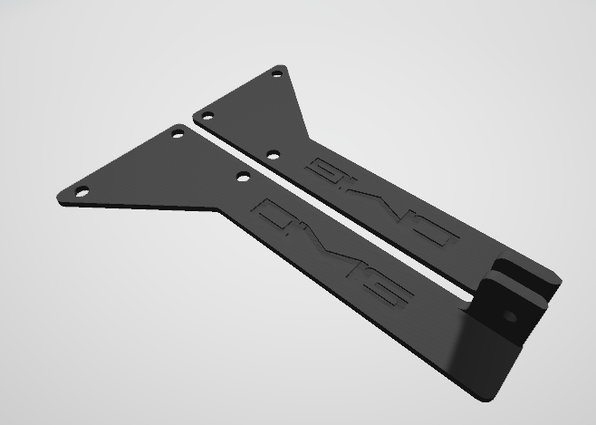
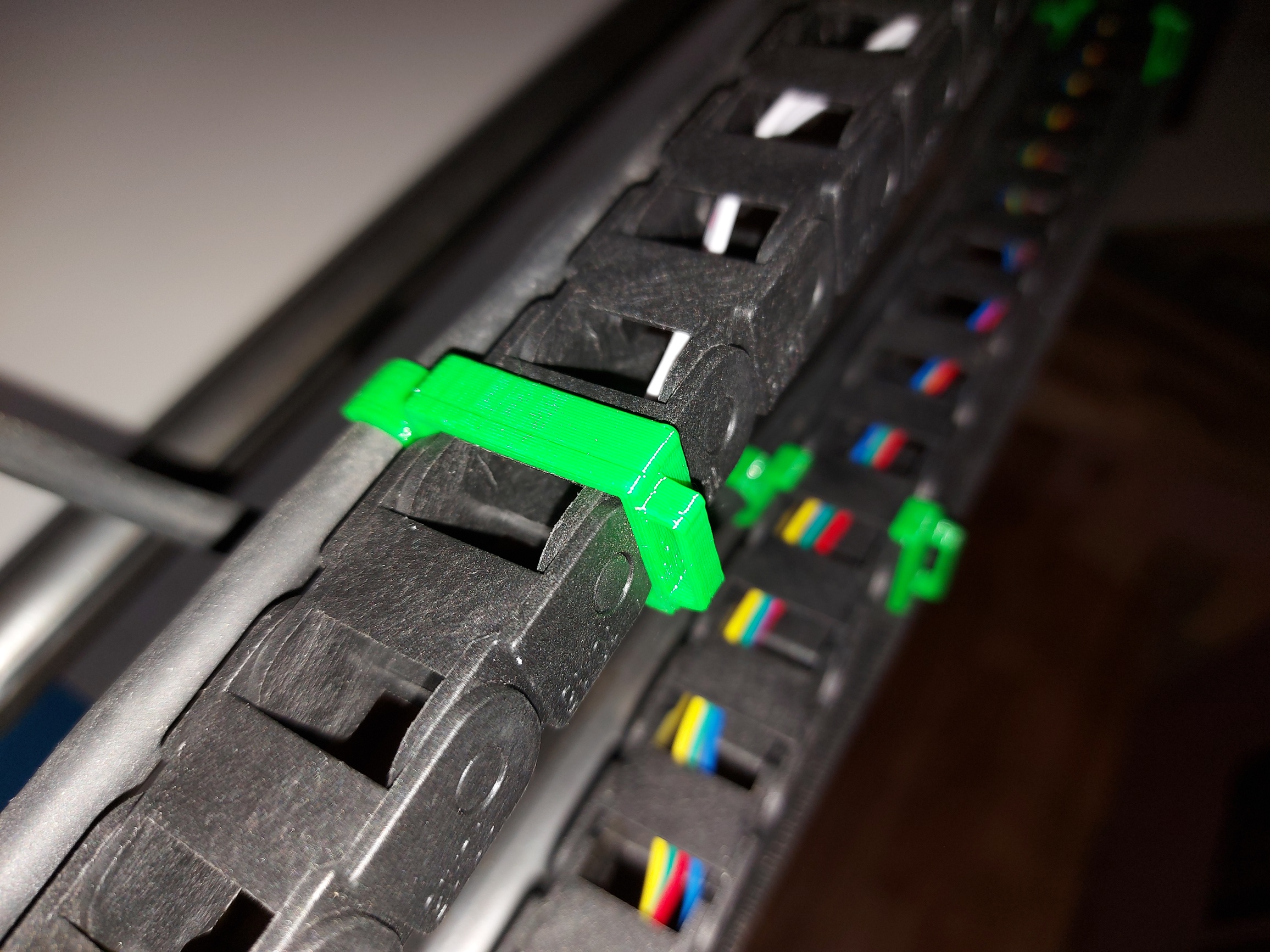
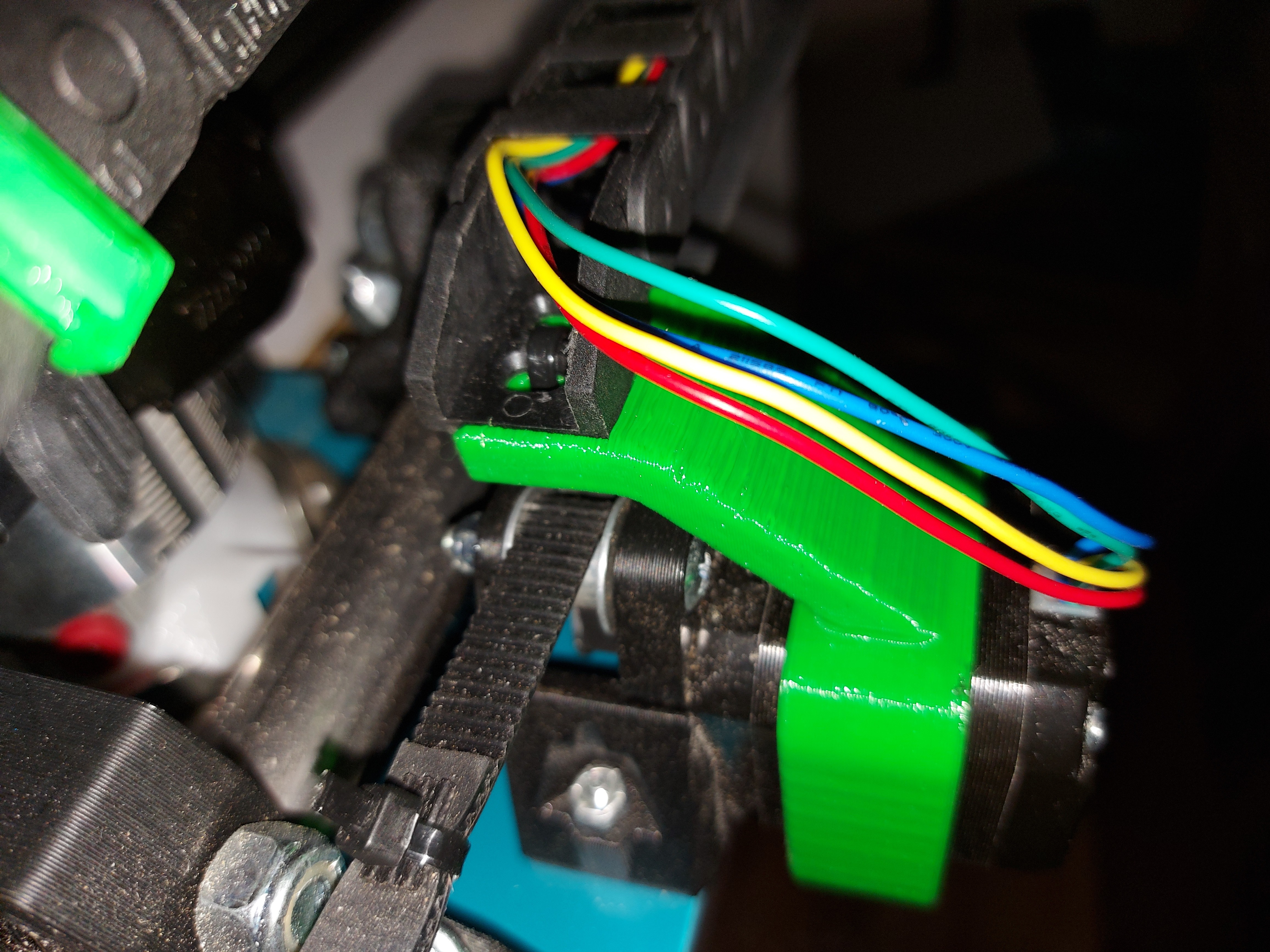
They clip over the 10x15mm drag chain, and the power cord snaps in. This way R&R the router is super easy, but the power cord is still out of the way. There are also loops on the opposite end which I intended for dust collection.
Also made a mount for the motor end of the drag chain.
Might re-think this again. I gave it an upward tilt, but it still sags. Sideways like I do for the Primo is probably better, but will require a little more thought into the Y plate end.
Yeah, I could just do the angle, like the provisions are there for, I just wanted to try this. Even if I don’t end up using it here, I very like will on the Primo, so it’s not a waste.
Besides, experiment and learn, right?
Looks like my T track won’t get here before the weekend, and due to a dental emergency, my bank account doesn’t like the idea of buying the spoilbiard pieces before then anyway, so still a ways away from regular cutting with the LowRider, so looks like I should re-work the Y bump stops and maybe look at fine tuning Z levelling.
I do have a question though, in your Sandify Clover video I noticed that not all lines connect. Is this because of the original file, your pen or inaccuracy?
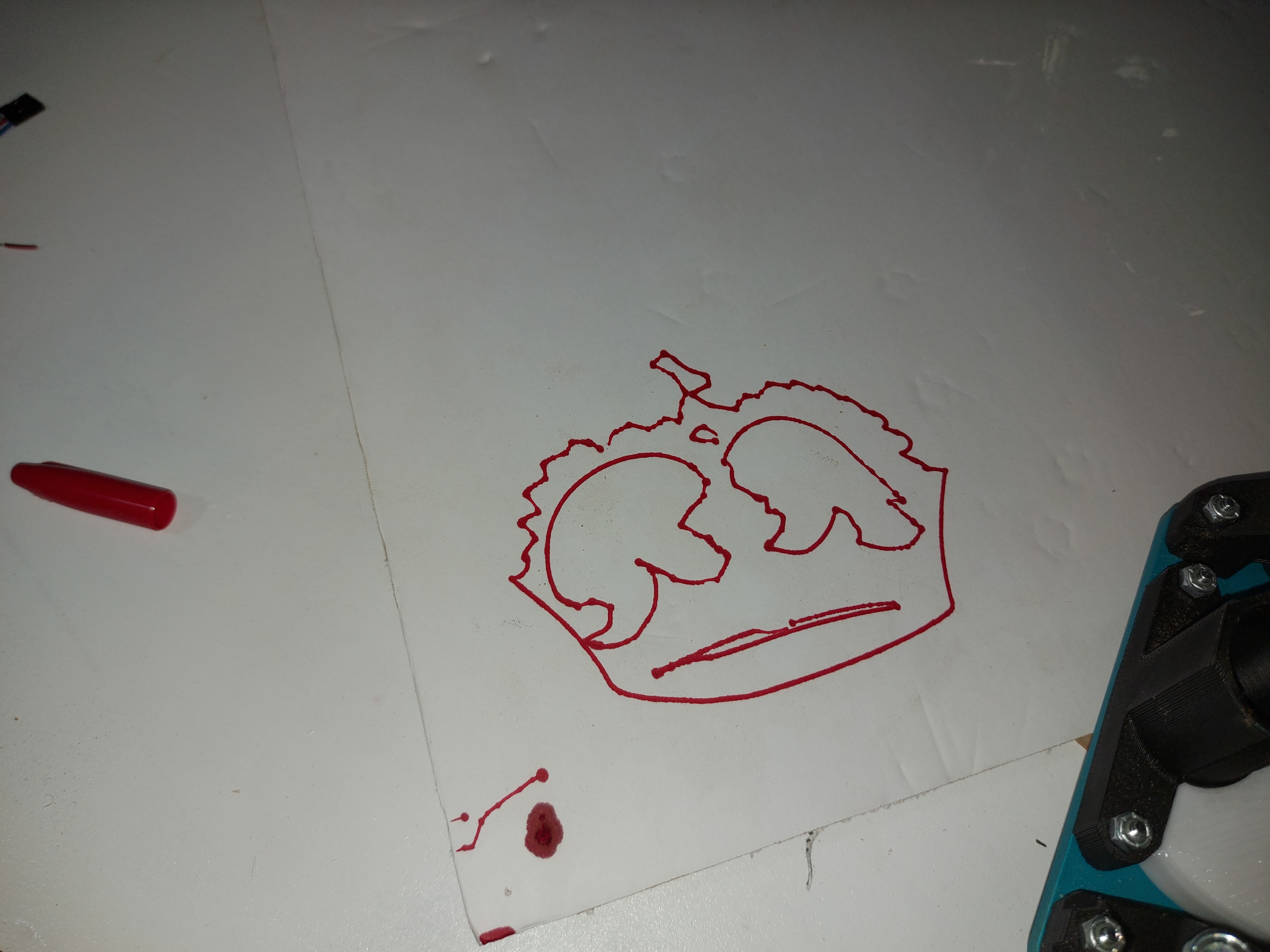
As far as I’d had it in that video, there are no breaks in the line. That drawing is one contiguous line that spirals outwards from the centre.
On the far side, the pen gets pushed down a bit too far and it starts to lag behind the intended path a bit, so the corners aren’t as sharp as they should be. When that job finished, there are a few lines in the near side where the pen did lift off of the paper in the middle of the loop. When I had powered the machine on, the X plate had landed on top of something, and was about 3-4mm higher on the minimum side of X (Which is why I decided to do the auto-square build, though I didn’t actually square Z before running that job )
So I did adjust my Z endstops, so they’re a lot more even now, and should be able to get even better results. I’ll have to try it again eventually.
Well, my 4 pieces of T track arrived. I would probably be OK with them at that length, but I think I’m going to place an order for another piece ASAP.
I have a bit to wait before I will be ready to do the spoilboard, but I have some 3/4" MDF in the garage so maybe I’ll get started on that. The pieces aren’t long enough though, as they have 49" as their longest dimension. I don’t think I have quite enough to do the whole spoilboard anyway, but I’ll see what I can figure out. I might have more if I use 5/8" material, I’ll have to look.
I was thinking that I might make pieces that are 12" by 15" in size, and tile them so that 4 of them span the 5’ table. That way, I can quickly replace a single piece that gets a little too chewed up.
Once I have the spoilboard set up, I should be ready for production!
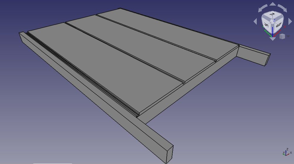
So I decided on the 12" by 15" pieces after all. I haven’t screwed down the T track yet. I’m 8 pieces short for the whole table, because that’s what I had, but I can get more. I need 3" wide pieces for each side, too.
I’m considering not screwing the spoilboard pieces down at all, letting the T track and whatever clamping I use for the work to hold it all in place. That way, I can flip the spoilboard pieces over, or relocate them easily when they get chewed up. I can also remove them for cleaning the table. Maybe I’ll just put screws in the pieces at the ends to keep them from sliding out while there’s nothing clamped down. I’ll have to see how it works out.
Keep in mind, the low rider has a big plate just above the bit. That’s why I never invested in reusable clamps. I just screw everything into the spoil board. I use some scraps to hold down pieces that I can’t add extra screws into.

 )
)